Trinh Cong Truong![]() | Thanh Nguyen Vu*
| Thanh Nguyen Vu*![]() | Hung Bui Duc
| Hung Bui Duc![]() | Vuong Dang Quoc
| Vuong Dang Quoc![]()
© 2023 IIETA. This article is published by IIETA and is licensed under the CC BY 4.0 license (http://creativecommons.org/licenses/by/4.0/).
OPEN ACCESS
The permanent magnet synchronous motors (PMSMs) have been widely used in industrial applications due to the high efficiency, reliable performance and different shapes and sizes. Based on the arrangement of permanent magnets (PMs), the PMSM can be split into two primary types, i.e., surface-mounted permanent magnet (SPM) motors and interior permanent magnet (IPM). For the SPM motor, PMS are mounted on the rotor surface, while the IPM has the magnets embedded into the rotor. The use of PMs for the PMSMs has eliminated the necessity for excitation currents, thanks to the high flux density and significant coercive force. The resulting absence of excitation losses plays a key role in enhancing overall efficiency. This research, introduces a multi-objective optimal design strategy for a surface-mounted PMSM, with the primary goal of achieving maximum efficiency while minimizing material costs. The optimization is carried out through the application of a genetic algorithm. In addition, a finite element method is proposed to validate a comprehensive assessment and comparison of the variances between the initial design and optimal design. The proposed methods are applied to the practical problem of 5.5 kW SPMSM. The FEM and calculation results showed that the motor’ s efficiency increased 0.5% and material cost decreased 15.2$ after the optimization process, both are the expected results.
surface-mounted permanent magnet synchronous motor (SPMSM), cogging torque, torque ripple, genetic algorithm (GA), finite element method
As we have known the permanent magnet synchronous motor (PMSM) has gained widespread adoption in various industrial applications owing to the reliability, compact size, high efficiency, and its adaptability to a range of shapes and sizes [1]. Especially, at low speeds, the PMSMs find extensive applications in fields such as ship propulsion, lifting, mining, and oil field exploitation [2, 3]. The PMSMs can be categorized into two main types based on the arrangement of the permanent magnet (PM): interior permanent magnet (IPM) motors, where magnets are embedded into the rotor, and surface-mounted PM (SPM) motors, where the PMs are mounted on the rotor surface. These motors are excited by PMs without using the excitation currents, leveraging their high flux density and significant coercive force. This unique characteristic eliminates excitation losses, leading to a substantial increase in efficiency [4].
In order to obtain the high torque, the fractional-slot concentrated winding is a commonly utilized configuration. This winding arrangement, termed a fractional-slot winding, involves a non-integer number of slots per pole per phase, less than one. When each coil of the winding is wound around each stator tooth, it is referred to as a concentrated winding. Motors featuring this type of winding offer significant advantages in low-speed direct drive transmission systems, including high efficiency, reduced end turn length, high slot fill factor, and low copper loss. However, the fractional-slot configurations come with drawbacks, such as a slightly lower winding factor and higher harmonic content in the magnetomotive force (MMF) distribution compared to integral slot machines [5, 6]. Consequently, the motor design must carefully consider the appropriate combination of the number of pole pairs and slots based on its intended applications.
The genetic algorithm (GA) is a search heuristic commonly utilized to produce efficient solutions for optimization and search problems. Drawing inspiration from natural evolution, the GA incorporates techniques such as inheritance, mutation, selection, and crossover to generate solutions for optimization problems. Its versatility renders it a robust tool for global optimization and the analysis of extensive datasets [7]. Many researchers have extensively applied GAs to investigate optimal designs for PMSMs [8-13]. However, the discrete variation of variables and their incomplete correlation with each other and other parameters can result in alterations to output power following the optimization process. The magnetic strength of Neodymium-iron-boron magnets (NdFeB) are stronger than Samarium Cobalt (SmCo) magnets and Ferrite magnets. Moreover, they are relatively inexpensive.
In this paper, a surface-mounted permanent magnet synchronous motor (SPMSM) using the magnet of NdFeB N35 is designed. Subsequently, the GA is applied to determine the optimal dimensions that achieve maximum efficiency while minimizing material costs (such as electrical steel, copper, and magnets) with power conservation.
The electromagnetic torque (Te) is computed via the expression as
$T_e=\frac{\pi}{4} D_{i s}^2 L \cdot T R V$ (1)
where, Dis is the inner diameter of stator, L is the length of machine, TRV is the torque density following to the volume (kNm/m3), its value is from 35 kNm/m3 to 85 kNm/m3 [14-16]. However, to determine the rotor volume (Vo), it relies on a coefficient concept that depends on the cooling systems, as presented in [17], that is,
$V_o=\frac{D_{i s}^2 L}{T_e}$ (2)
It should be noted that the value of Vo will be taken depending on the output power and the method of cooling.
The magnet thickness can be calculated as:
$h_{m a g}=\frac{\mu_r g B_{a i r-g} \pi}{B_r 4 \sin \left(\frac{\rho_{ {mag }}}{2}\right)-B_{ {air }-g} \pi}$ (3)
where, $\rho_{{mag}}$ is the electrical angle, Br is the magnetic flux density in rotor, $\mu_r$ is the magnet permeability, g is the length of air gap, and Bair-g is the magnetic flux density in the air gap between stator and rotor. The value on Bair-g can be defined as:
$B_{ {air }-g}=\frac{4}{\pi} \sin \left(\frac{\rho_{ {mag }}}{2}\right) B_{m a g}$ (4)
where, Bmag is the magnetic flux density of PM.
The iron loss (piron) of the PMSM due to the hysteresis eddy current losses and additional loss can be defined as [18]:
$p_{ {iron }}=k_h f B_{ {mag }}^\alpha+k_e f^2 B_{ {mag }}^2+k_a f^{1,5} B_{ {mag }}^{1,5}$ (5)
where, factors kh, ke, ka and α are given in the study [19].
In this paper, the iron loss and copper loss accounted for the main proportion of the total loss of the motor. Thus, we assumed that the total loss is the sum of the iron loss and the copper loss, which is given as below:
$P_{ {total \,loss }}=P_{{Fe}}+P_{{Cu}}$ (6)
where, PFe is the loss appearing in the stator, rotor and teeth of the motor, and PCu is the copper loss which can be defined as follows:
$P_{C u}=N_S I^2 R$ (7)
where, Ns is the number of slots, I is the phase current and R is the resistance of the winding in each tooth.
The optimization process of the PMSM is performed via the GA diagram as shown in Figure 1. It involves a multi-objective problem with numerous variables and constraints. The careful selection of variables is paramount, as it exerts a direct influence on the outcome. In this investigation, a meticulous evaluation resulted in the incorporation of seven variables within the optimization procedure as given in Table 1, where variables x1, x2, x3, x4, x5, x6, x7 are respectively the inner stator diameter, air gap length, height of the stator yoke, height of the rotor yoke, width of the tooth, current density and turn number per tooth.
Figure 1. GA for a multi-objective genetic algorithm
Table 1. Upper and lower boundaries of optimal variables
|
Variable |
Lower Boundary |
Upper Boundary |
|
x1 (mm) |
120 |
140 |
|
x2 (mm) |
0.7 |
1 |
|
x3 (mm) |
12 |
17 |
|
x4 (mm) |
12 |
17 |
|
x5 (mm) |
12 |
17 |
|
x6 (A/mm2) |
4.5 |
5.5 |
|
x7 (turns) |
55 |
65 |
The variables x1, x3, x4 and x5 are related to steel volume and iron loss, whereas x2, x6, and x7 are associated to the magnet dimensions and copper loss. The precise formulation of proposed constraints is essential to guarantee that the optimization outcomes align with the operational requirements of the PMSM. This study centers on three key parameters: stator volume, rotor volume, and magnet volume. The stator volume is proportional to the power of the motor. Thus, this value was kept constant in order to ensure the power conservation of the motor. From the Eq. (1), it can be seen that the output torque of the motor is proportional to the rotor volume, so this value also remains to keep the output torque as a constant. The PM is the part which produced magnetic flux in the air gap. Therefore, only a minor change in the magnet volume will cause a change in the magnetic flux in the air gap, thereby changing the power and the torque of the motor. Thus, this value was also kept as a constant. Each volume of the three parts (i.e., stator, rotor, PM) accompanied by an equality constraint: 1T ≤ Bsy ≤ 1.5T; 1.3T ≤ Bry ≤ 1.6T; 1.5T ≤ Btooth ≤ 2T; 0.45 ≤ kfill ≤ 0.55, where Bsy, Bsy and Btooth are the magnetic flux densities in the stator, rotor and tooth, respectively. The kfill is the slot fill factor. It should be noted that the volumes of the stator (Vstator), rotor (Vrotor) and the magnet (Vmagnet) are considered as a constant. In addition, the values of flux density of the stator yoke, rotor yoke, and tooth of the PMSM are the four inequality constraints already given in the study [20].
Additionally, it is essential to define the objective functions, with a particular focus on minimizing total loss and material cost. The material cost includes expenses related to electrical steel, copper, and magnets, outlined as follows:
$\begin{gathered}C=c_{F e}\left(M_{ {stator }}+M_{ {rotor }}+M_{ {teeth }}\right)+c_{C u} M_{C u} +c_{ {mag }} M_{ {mag }}\end{gathered}$ (8)
where, $c_{F e}, c_{C u}, c_{m a g}$ are the cost per kilogram of electrical steel, copper and PM, respectively. The terms $M_{ {stator }}, M_{ {rotor }}$, $M_{ {teeth }}, M_{C u}$ and the $M_{m a g}$ are respectively the masses of stator, rotor, teeth, copper and PM. These values are defined as follows:
$M_{ {stator }}=Y_1 \frac{4 Y_2 x_1 x_3-4 x_3^2}{x_1^2}$ (9)
$M_{ {rotor }}=Y_1 \frac{\left(x_1-2 K_3 x_2\right)^2-\left(x_1-2 K_4 x_2-2 x_4\right)^2}{x_1^2}$ (10)
$\begin{gathered}M_{ {teeth }}=\frac{Y_1}{x_1^2}\left(\frac{\pi}{4}\left(Y_2 x_1-2 x_4\right)^2-Q_s\left(\frac{Y_2-1}{2} x_1-x_3-\right.\right. \left.Y_5\right)\\\left(\frac{Y_2+1}{2} x_1-\frac{Y_7}{Y_5} x_3-x_5+Y_7\right)+Q_s Y_8+Y_8 \frac{h_w}{2}\left(\frac{Y_7}{Y_5} x_1-\right. \left.x_5\right)\end{gathered}$ (11)
$\begin{gathered}M_{C u}=\frac{Y_9}{x_6} 2 x_6 Y_5+\frac{Y_{10}}{x_6} 2 x_6 \frac{V_{ {rotor }}}{x_1^2}+ \\ \frac{Y_9}{x_6} 2 x_6 \frac{Y_8}{\sqrt{x_7}}\left(\frac{x_7}{\left(\frac{\left(\frac{Y_2-1}{2} x_1-x_3-Y_5\right) \sqrt{1+a_1^2}}{Y_8} \sqrt{x_6}\right)}\right)\end{gathered}$ (12)
where, the factors Y1, Y2, Y3, Y4, Y5, Y6, Y7, Y8 and Y9 are respectively given as:
$\begin{aligned} & Y_1=\frac{\pi}{4} 10^{-9} \gamma_{F e} V_{\text {rotor }}, Y_2=\sqrt{\frac{V_{ {stator }}}{V_{ {rotor }}}}, Y_3=\frac{\mu_r}{\frac{B_{r m a g}}{B_{m a g}}-1}+1, \\ & Y_4=\frac{1}{4}\left(Y_2^2-1\right)-\frac{K_2+1}{2} Y_5, Y_5=h_w+h_{s o}, Y_6=\frac{\pi K_5}{Q_s}, \\ & Y_7=h_{s o} b_{s o}+\frac{1}{2} h_w b_{s o}+\frac{\pi h_w Y_5}{Q_s}, \\ & Y_8=1,095 \sqrt{\frac{4 I}{\pi}}, Y_{10}=\frac{\gamma_{c u} I}{10^{-6}} .\end{aligned}$
The other parameters $V_{ {stator }}, V_{ {rotor }}, B_{ {rmag }}, B_{ {mag }}, h_w, h_{\text {so }}$, $b_{s o}, \gamma_{F e}$ and $\gamma_{C u}$ represent the volume of stator, rotor, the operating remanence of the magnets at working temperature, the flux density above the magnets, the wedge height, the tooth tip depth, the opening width of the semi-closed slot; the mass density of electrical steel and copper, respectively. In addition, the mass of the PM can be determined via the PM volume (Vmag).
$M_m=10 \gamma_m V_m 10^{-9}$ (13)
The cost is considered as a function of the variables, i.e.,
$C=f_1(x)=f_1\left(x_1, x_2, x_3, x_4, x_5, x_6, x_7\right)$ (14)
The losses in the stator, rotor and tooth are computed as:
$P_{ {stator }}=\frac{Y_{11}}{\left(x_2 x_3 x_1^{-2}\right)^{1,6}}+\frac{Y_{12}}{\left(x_2 x_3 x_1^{-2}\right)^2}$ (15)
$P_{ {rotor }}=\frac{Y_{11}}{\left(x_2 x_4 x_1^{-2}\right)^{1,6}}+\frac{Y_{12}}{\left(x_2 x_4 x_1^{-2}\right)^2}$ (16)
$P_{ {tooth }}=\frac{Y_{13}}{\left(x_2 x_5 x_1^{-2}\right)^{1,6}}+\frac{Y_{14}}{\left(x_2 x_5 x_1^{-2}\right)^2}$ (17)
for
$\begin{aligned} & Y_{11}=k_h f\left(\frac{B_m V_m\left(Y_3-1\right)}{2 V_{ {rotor }} k_j} 10^{-6}\right)^{1,6}, \\ & Y_{12}=k_e f^2\left(\frac{B_m V_m\left(Y_3-1\right)}{2 V_{ {rotor }} k_j} 10^{-6}\right)^2, \\ & Y_{13}=k_h f\left(\frac{\pi B_m V_m\left(Y_3-1\right)}{Q_s V_{ {rotor }} k_j} 10^{-6}\right)^{1,6}, \\ & Y_{14}=k_e f^2\left(\frac{\pi B_m V_m\left(Y_3-1\right)}{Q_s V_{ {rotor }} k_j} 10^{-6}\right)^2,\end{aligned}$
where, f is the frequency stacking factor and. and kj is the iron lamination. The winding resistance in each tooth can be defined as:
$\begin{gathered}\mathrm{R}=2 Y_{15} x_6 x_7\left(x_5+\frac{V_{ {rotor }}}{x_1^2}\right)+ Y_{15} x_6 x_7 \frac{Y_9}{\sqrt{x_6}} {ceil}\left(\frac{x_7}{{floor}\left(\frac{\left(\frac{Y_2-1}{2} x_1-x_3-k_5\right) \sqrt{1+a_1^2}}{Y_9} \sqrt{x_6}\right)}\right)\end{gathered}$ (18)
$P_{ {total \,loss }}=f_2(x)=f_2\left(x_1, x_2, x_3, x_4, x_5, x_6, x_7\right)$ (19)
The test problem is a practical SPMSM of 5.5kW as presented in Figure 2. The main parameters are given in Table 2.
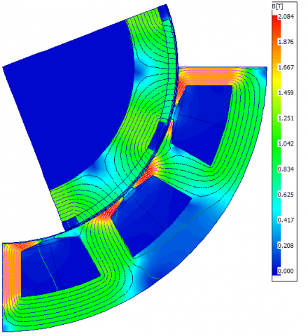
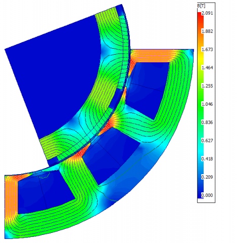
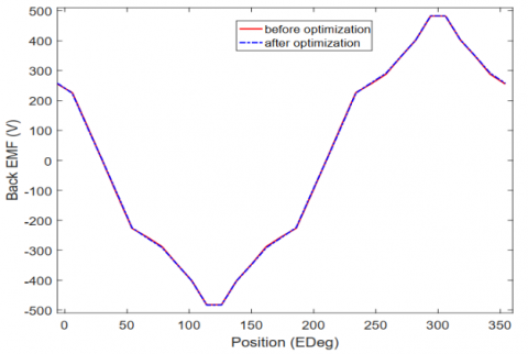
The distribution of magnetic flux densities in the SPMSM before and after optimization is pointed out in Figure 3 and Figure 4. It can be seen that the value of B focuses on the tooth with a maximum value of 2.084 (T), and for 2.091 (T) after optimization. This implies a marginal rise in flux density on the tooth, accompanied by a reduction in total loss. Consequently, this alteration will not adversely impact the operational parameters of the proposed motor. In addition, the output power is also increase from 5530W upto 5548W. The distribution of the back electromotive force (EMF) before and after optimization is shown in Figure 5. It shows that before optimization, the RMS of back EMF is 311.3V, and 311.9V for after optimization, showing an increase of 0.6V. However, both of these values are still below the supply voltage of 353.6V. It should be noted that the efficiency of the machine increases by 0.33%, rising from 93.97% before optimization to 94.3% after optimization.
Figure 2. 2D Model of SPMSM of 5.5kW, 12slots, 2p=8 (top) and winding diagram (bottom)
Table 2. Main parameters of SPMSM
|
Parameter |
Value |
Unit |
|
Rated Power |
5500 |
W |
|
DC voltage (DC bus) |
500 |
V |
|
Number of slot |
12 |
slot |
|
Number of pole pairs |
4 |
plole |
|
Rate torque |
70 |
N.m |
|
Frequency |
50 |
Hz |
Figure 3. Magnetic flux density distribution in the SPMSM before optimization.
Figure 4. Magnetic flux density distribution in the SPMSM after optimization
Figure 5. Back EMF distribution for before and after optimzations
Figure 6. Output torque before and after optimzations
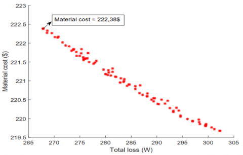
Figure 7. Pareto front results
The waveform of the output torque before and after optimzations is presented in Figure 6. The torque at the motor shaft is also increased after optimization, going from 70.4 Nm to 70.65 Nm. Therefore, after the optimization process, both power, efficiency, and torque at the motor shaft are elevated. The torque ripple remains nearly unchanged, at 25.9% before optimization and 25.8% after optimization. However, whether before or after optimization, the torque ripple values are relatively high, indicating a need for adjustments to reduce the torque ripple.
Figure 7 presents the Pareto front results of the objective functions. It can be observed that the two objective functions, namely material cost and total loss, exhibit an inverse relationship: as material cost decreases, total loss increases, and vice versa. In this paper, the author selects the point of the minimum value of the sum of these two optimized functions to carry out the process of calculating parameters for the motor after optimization. The optimal results on main parameters of the SPMSM is given in Table 3. It should be noted that the efficiency after optimization is smaller that that before optimization.
Table 3. Optimal results on main parameters of the SPMSM
|
Parameters |
Before Optimization |
After Optimization |
|
Stator outer diameter (mm) |
204.68 |
203.29 |
|
Stator inner diameter (mm) |
136.58 |
135.64 |
|
Tooth width (mm) |
14.43 |
14.3 |
|
Slot height (mm) |
17.91 |
17.93 |
|
Magnet thickness (mm) |
3 |
3 |
|
Magnet electrical angle |
140 |
139 |
|
Active length of iron core (mm) |
136.58 |
138.46 |
|
Number of turns |
56 |
56 |
|
Conductor diameter (mm) |
1.72 |
1.7 |
|
Slot fill factor |
0.54 |
0.55 |
|
Power (W) |
5530 |
5548 |
|
Phase back EMF (V) |
179.7 |
180.1 |
|
Efficiency (%) |
93.97 |
94.3 |
|
Torque ripple (%) |
25.9 |
25.8 |
|
Power factor |
0.9 |
0.9 |
In order to improve the efficiency without changing the output torque and power, a skewing technique for the PM is proposed in this part.
To apply the cross-magnetization technique, magnets need to be divided into smaller sections. In this study, each magnet is divided into five parts. Subsequently, it is necessary to choose the inclination angles for each part of the magnet. Moreover, these angles should be selected to be symmetrical across the 0-degree angle, as indicated in the table. In this research, these angles are randomly chosen to demonstrate the effectiveness of the cross-magnetization technique in smoothing the output torque waveform of the motor. However, these angles can also be optimized in other processes to achieve the best results for reducing torque ripple to the minimum value. The skewing PM with different angles is given in Table 4.
Table 4. Skewing PM with different angles
|
Slice |
Proportional Length |
Angle |
|
1 |
1 |
-6 |
|
2 |
1 |
-3 |
|
3 |
1 |
0 |
|
4 |
1 |
3 |
|
5 |
1 |
6 |
The model of skewing PMs and cogging torques of skewing PM are presented in Figure 8 and Figure 9. Obtained results after using skewing PM techique are given in Table 5. We observe that torque ripple has been significantly reduced after implementing the cross-magnetization technique. This result can be explained as follows: It is known that when the magnet is divided into segments, the total cogging torque is equal to the cogging torque caused by each magnet as it passes through each tooth.
Figure 8. Model of skewing PMs
Table 5. Obtained results after using skewing PM techique
|
Parameters |
Value |
Unit |
|
Output power |
5313 |
W |
|
Shaft torque |
67.65 |
Nm |
|
Efficiency |
94.3 |
% |
|
Torque ripple |
6 |
% |
Figure 10. Waveform of cogging torques in each slice after using the skew PM
The waveform of cogging torques in each slice after using the skew PM is pointed out in Figure 10. It can be seen that each cogging torque generated by a magnet in one cycle will have a different waveform depending on the magnet skew angle we choose. When these cogging torques are synthesized, they will cancel each other out, significantly reducing the total cogging torque, thereby smoothing the output torque curve of the motor. It can be observed that if we can choose the optimal magnet skew angle, the cogging torque can be nearly eliminated. However, after implementing magnet skewing, the average torque is reduced [3]. Furthermore, as the magnet skew angle increases, the torque ripple is reduced, but the average torque also decreases [4].
To maintain constant power, or in other words, preserve the required output torque, two methods can be employed: increasing the thickness of the magnets or reducing the air gap. While increasing the magnet thickness is effective, it raises material costs. Therefore, the option of reducing the air gap is chosen and implemented. As we know, the magnetic flux generated by the magnets is constant. However, depending on the size of the air gap, the leakage flux and stray flux will vary. A larger air gap results in larger leakage and stray flux, leading to greater power loss. Conversely, a smaller air gap reduces these flux components, resulting in a smaller power loss. Additionally, reducing the air gap does not impact material costs, meaning it does not affect the optimization objective mentioned earlier. The value of the air gap cannot be too small, as it would pose challenges in manufacturing. After the calculation process, a new air gap value of 0.65 mm is applied for simulation. The simulation results are presented in Table 6.
Table 6. Simulated results after using skewing PM techique with air gap of 0.65mm
|
Parameters |
Value |
Unit |
|
Power |
5524 |
W |
|
Shalf torque |
70.3 |
Nm |
|
Efficiency |
94.4 |
% |
|
Torque ripple |
6.8 |
% |
The output torque before and after airgap length adjustment is presented in Figure 11. So, after adjustment, the motor power has been increased to the required value, with efficiency rising by an additional 0.1%, from 94.3% to 94.4%. The output torque also reaches 70.3 N.m, slightly exceeding the required value of 70 N.m. The torque ripple, after reducing the air gap length, has increased slightly from 6% to 6.8%. These values are all within an acceptable range and do not significantly impact the machine operation.
The back EMF before and after airgap length adjustment is presented in Figure 12. It shows that before adjustment, the back EMF is 297.7 and it increases to 310.6V for after optimization. Both of these values are still lower than the supply voltage of 353.6V.
Figure 11. Output torque before and after airgap length adjustment
Figure 12. Back EMF before and after airgap length adjustment
Figure 13 shows the harmornic components of back EMF. We can see that after using the skew PM technique, the harmonic components of 5th, 7th and 11th order of the EMF have significantly reduced. Therefore, the waveform of the EMF after using the skew PM technique has become much more sinusoidal. The magneic flux density distribution at the air gap for different positions with the skew PM is presented in Figure 14. The maximum value is obtained 1.2 (T). The fux linkage density at the air gap for no and full loads with the skew PM is shown in Figure 15. The waveform is quite sinousoidal and smooth for both cases.
Figure 13. Harmornic components of back EMF
Figure 14. Magneic flux density distribution at the air gap for different positions with the skew PM
Figure 15. Flux linkage density at the air gap for no and full loads with the skew PM
This paper has successfully proposed the GA to optimize the SPMSM of 5.5kW. The primary goal of the optimization process was to minimize two critical factors: total loss and material cost. To assess the effectiveness of the chosen variables and constraints in the optimization method, the motor efficiency was evaluated using the FEM. The results indicate that the optimized design not only significantly reduces material costs compared to the original design while maintaining the desired efficiency level but also induces favorable changes in other parameters like cogging torque and torque ripple. In addition, the skew PM technique has been also developed to improve the efficiency, output torque, cogging torque and the back EMF.
In the future work, it could be explored the development and optimization of additional objective functions, including torque output, cogging torque, and torque ripple. Additionally, other optimization methods such as particle swarm optimization, cultural algorithm, bee algorithm, and more could be employed to address optimization challenges and achieve even more optimal outcomes.
This research is funded by Hanoi University of Science and Technology under project number T2022-PC-008.
[1] Zhang, H., Dong, Z., Zhou, J. (2017). Optimization design and analysis of permanent magnet synchronous motor based on VC. In 2017 20th International Conference on Electrical Machines and Systems (ICEMS) Sydney, Australia, pp. 1-4. https://doi.org/10.1109/ICEMS.2017.8055957
[2] Crider, J.M., Sudhoff, S.D. (2015). An inner rotor flux-modulated permanent magnet synchronous machine for low-speed high-torque applications. IEEE Transactions on Energy Conversion, 30(3): 1247-1254. https://doi.org/10.1109/TEC.2015.2412547
[3] Feng, L., Yu, S., Zhang, F., Jin, S., Sun, Y. (2021). Study on performance of low-speed high-torque permanent magnet synchronous motor with dynamic eccentricity rotor. Energy Reports, 8: 1421-1428. https://doi.org/10.1016/j.egyr.2022.03.018
[4] Qinghua, L. (2005). Analysis, design and control of permanent magnet synchronous motors for wide-speed operation. Doctoral Thesis, National University of Singapore, Singapore.
[5] Hwang, C.C., Lyu, L.Y., Liu, C.T., Li, P.L. (2008). Optimal design of an SPM motor using genetic algorithms and taguchi method. IEEE Transactions on Magnetics, 44(11): 4325-4328. https://doi.org/10.1109/TMAG.2008.2001526
[6] Zhao, W., Shen, H., Chai, W., Wang X., Kwon, B.I. (2018). Optimal design and experimental test of a SPM motor with cost-effective magnet utilization to suppress torque pulsations. IEEE Transactions on Magnetics, 54(11): 1-5. https://doi.org/10.1109/TMAG.2008.2001526
[7] Mendaci, S., Allag, H., Mekideche, M.R. (2015). Multi-objective optimal design of surface-mounted permanent magnet motor using NSGA-II. The Applied Computational Electromagnetics Society Journal, 30(5): 519-526.
[8] Braiwish, N. (2016). Design optimisation of brushless permanent magnet synchronous motor for electric vehicles. Doctoral Thesis, Wolfson Centre for Magnetics, School of Engineering, Cardiff University, UK.
[9] Gao, J., Dai, L., Zhang, W. (2018). Improved genetic optimization algorithm with subdomain model for multi-objective optimal design of SPMSM. CEs Transactions on Electrical Machines and Systems, 2(1): 160-165. https://doi.org/10.23919/TEMS.2018.8326463
[10] Tun, E.K.A.N., Tin, T. (2014). Design of conventional permanent magnet synchronous motor used in electric vehicle. International Journal of Scientific Engineering and Technology Research, 3(16): 3289-3293.
[11] Gu, W., Zhu, X., Quan L., Du, Y. (2015). Design and optimization of permanent magnet brushless machines for electric vehicle applications. Energies, 8(12): 13996-14008. https://doi.org/10.3390/en81212410
[12] Liu, H. (2015). Design of high-efficiency rare-earth permanent magnet synchronous motor and drive system. Doctoral Thesis, University of Central Florida, USA.
[13] Liu, G., Liu, M., Zhang, Y., Wang, H., Gerada, C. (2020). High-speed permanent magnet synchronous motor iron loss calculation method considering multi-physics factors. IEEE Transactions on Industrial Electronics, 67(7): 5360-5368.
[14] Sundaram, M., Anand, M., Chelladurai, J., Varunraj, P., Smith, S.J., Sharma, S., Assad, M.E.H., Alayi, R. (2022). Design and FEM analysis of high-torque power density permanent magnet synchronous motor (PMSM) for two-wheeler e-vehicle applications. International Transactions on Electrical Energy System. https://doi.org/10.1155/2022/1217250
[15] Seo, U.J., Chun, Y.D., Choi, J.H., Chung, S.U., Han, P.W., Koo, D.H. (2013). General characteristic of fractional slot double layer concentrated winding synchronous machine. Journal of Electrical Engineering and Technology, 8(2): 282-287.
[16] Jussila, H., Salminen, P., Niemelä, M., Pyrhönen, J. (2007). Guidelines for designing concentrated winding fractional slot permanent magnet machines. In 2007 International Conference on Power Engineering, Energy and Electrical Drives, pp. 191-194. https://doi.org/10.1109/POWERENG.2007.4380186
[17] Mishra, S., Sahoo S., Das, M. (2017). Genetic algorithm: An efficient tool for global optimization. Advances in Computational Sciences and Technology, 10(8): 2201-221.
[18] Hong, G., Wei, T., Ding, X. (2018). Multi-objective optimal design of permanent magnet synchronous motor for high efficiency and high dynamic performance. IEEE Access, 6: 23568-23581. https://doi.org/10.1109/ACCESS.2018.2828802
[19] Pluta, W.A. (2011). Core loss models in electrical steel sheets with different orientation. Przegląd Elektrotechniczny, 87(9b): 37-4.
[20] Ponomarev, P. (2013). Tooth-coil permanent magnet synchronous machine design for special applications. Doctoral Thesis, Lappeenranta University of Technology, Finland.