Ghada A. Mutuab*![]() | Mohammed Y. Hassan
| Mohammed Y. Hassan![]()
© 2023 IIETA. This article is published by IIETA and is licensed under the CC BY 4.0 license (http://creativecommons.org/licenses/by/4.0/).
OPEN ACCESS
The Fluid Catalytic Cracking Unit (FCCU) serves as the lifeblood of a modern refinery, playing a crucial role in ensuring superior product quality. This paper delves into the design of a nonlinear Proportional-Integral-Derivative (PID) control mechanism aimed at regulating the temperature of both the reactor and the regenerator within the FCCU. A total of four nonlinear PID controllers have been meticulously designed, two each for controlling the temperature of the reactor and the regenerator. Utilizing the cross-coupling method, these controllers are proficient in compensating for the effects of cross-coupling and the nonlinearities inherent in the model. The Firefly algorithm, renowned for its capability in finding optimal solutions to intricate optimization problems, has been employed for tuning the parameters of the controllers. The outcomes discussed in this paper underscore the transient responses of the reactor temperature, featuring an overshoot of 0.239% and a rise time of 24.87631 sec. For the regenerator temperature, the overshoot stands at 0.703% with a rise time of 25.636 sec. These results highlight significant improvements in product quality, achieved by enhancing and closely monitoring the temperatures of both the reactor and the regenerator within the FCCU—an aspect of paramount importance in the oil industry.
FCCU, nonlinear PID control, PID
The FCCU is a key component of petroleum refineries that uses catalytic cracking to transform heavy hydrocarbon feedstock into lighter products. A reactor in which the cracking reaction occurs and a regenerator in which the catalyst is renewed make up the FCCU reactor-regenerator system. Since catalytic cracking has developed into a significant secondary process in refineries, parameter estimation of the reaction's kinetics is now required [1].
Even though many different control theories have been established, well-known industrial settings continue to use Proportional-Integral-Derivative (PID) controllers frequently process control. The terms for Proportional, Integral, and Derivative (PID) in the three-mode controller enable a system to provide a desired response regarding the settling time, steady-state error, and overshoot [2]. The Proportional-Integral-Derivative (PID) controller, one of the most popular control algorithms in process control, has the potential to be very effective if properly tuned [3]. A typical illustration of an older type of controller is the PID controller. The monitoring error e(t) is calculated by comparing the input voltage and output speed [4]. Different operating conditions' requirements cannot be met by a standard PID controller. Linear PID controllers work well for regulating a typical physical action and achieving the required operating conditions, but they frequently fall short of the criteria for efficient control using changing operating circumstances or disturbances [5]. The linear PID in time representation [6] is:
$U(t)=K p \,\, e(t)+K i \int \,\, e(t) d t+K d \,\, d e(t) / d t$ (1)
The schematic of linear PID control is shown in Figure 1 [6].
Figure 1. Linear PID control [6]
where, e(t) is used to indicate the differences between the process value and the desired output. The error integral functions as an accumulator to enhance tracking. Overshoot is avoided by using the derivative of the error, which shows the rate of change in the error. PID has a number of disadvantages, including: (1) The differentiator causes noise amplification. (2) It can occasionally generate a strong signal for control owing to winding up, exceeding, and increasing the unwinding of the accumulated error. In order to improve performance in areas like increased damping and decreased tracking error, the control law is synthesized using a nonlinear combination of proportional, integral, and derivative action on the control error [7]. Therefore, for both predicting and changing the behavior of dynamic systems, it is essential to develop nonlinear analytical techniques for unexpected behavior to reach controller-required performance levels [8]. PID controllers are highly popular and widely used because they are straightforward model-free monitors that may be simply created and executed. In industry, there are several applications. Advanced regulation with varying operating circumstances or environmental elements, on the other hand, is frequently beyond the capability of typical PID controllers. As a result, numerous academics have attempted to increase the robustness of these controllers. The most recent study went on to design of Nonlinear PID (NPID) control to overcome the system's nonlinearity. NPID controllers can also be seen as an attempt to improve the performance of regular PID controllers. The time-varying gains in an NPID controller can be determined using neural networks and fuzzy systems [9]. The most recent study went on to design NPID control to overcome the system's nonlinearity and uncertainty. The PID controller's fixed gains are combined with nonlinear gains in the NPID controller. To achieve a quick dynamic response, these nonlinear gains benefit from a high initial gain, which, in order to avoid oscillatory behavior, is followed by a low gain [10]. NPID control is highlighted as one of these techniques that is most suitable and effective for industrial applications. There are two major categories in which this control has found use. In the first category for nonlinear systems where it is used to absorb nonlinearity, NPID control is used to achieve enhanced performance not possible with a linear PID control, such as reduced overshoot, decreased rise time for step or rapid command input, improved tracking accuracy within the second classification of linear systems.
The main goal of this paper is to monitor the Fluid Catalytic Cracking Unit's reactor and regenerator temperatures by designing the nonlinear PID control to achieve good product quality by designing four nonlinear PID controls two for controlling reactor temperature and two for regenerator temperature by the cross-coupling method. The parameters of the controllers are adjusted using the Firefly algorithm. This algorithm solves complex problems in various fields. In this work, it is used to find the best parameters of the controllers. This depends on the selected objective function which will be explained in the next paragraphs.
One of the most important steps in the refining of petroleum has been fluid catalytic cracking. In FCCU heavy oils (Gasoil and Residue) are subjected to a number of chemical processes, mostly cracking processes, to create value-added (Light gas oil and Jet Fuel and Residue) [11]. In this work, a fluidized-bed catalytic cracking unit's control system has been developed. The dynamic and control system is based on the reactor and regenerator systems' basic energy balance. Reactor temperature and regenerator temperature were selected as the key input variables for the control system [12].
2.1 FCCU process description
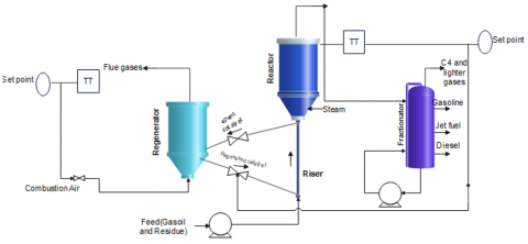
In Figure 2, a typical FCC unit is displayed [13]:
•It is made up of riser/reactor and regenerator units; the regenerator burns off the coke on the used catalyst while the riser/reactor completes the endothermic cracking reaction.
•Then the cycle is completed when the new catalyst returns to the riser/reactor with enough heat to meet the reactor's heat needs.
•Along with the powdered catalyst and steam, the preheated crude oil or feed is injected into the reactor's riser at its base.
•The main cracking product is lighter hydrocarbons, and as a byproduct, coke deposits on the catalyst surface, reducing the activity of the catalyst.
•To keep the regenerator temperature at a predetermined level, the control valve 1 modifies the amount of spent catalyst flow rate.
•To keep the riser temperature at a predetermined level, control valve 2 modifies the amount of regenerated catalyst flow rate.
•The transport lines as depicted in Figure 2 are used to recycle the used catalyst to the regenerator. The air blown into the regenerator burns the coke off the catalyst surface.
•A control valve 3 could regulate the air flow rate to the regenerator.
Figure 2. Schematic of FCCU processes [13]
2.2 Mathematical modeling for FCCU operation
By taking into account the energy and material balance, a model of FCCU that explains the changing dynamics of the reactor and regenerator has been created. In order to create an energy balance in the reactor and regenerator, the following presumptions are made [13]:
•Ignoring the terms for radiation, convection, and conduction.
•Heat of combustion and heat of reaction are both constant.
The reactor equations' energy balance equation is expressed as follows [13]:
Input stream – [Output Stream – Heat of reaction] = Rate of Accumulation (2)
Heat of regenerated catalyst + Heat of Feed + Heat of Steam – {Heat of effluent – Heat of Spent catalytic Heat of reaction} = Rate of Accumulation (3)
Frgc Cprgc Treg + Ff Cpf Tf + Fs Hs – Fp Cpp Trea – Fsc Cpsc Trea + Hrea = (Mp CPp+Msc Cpsc) dTrea / dt (4)
where, Frgc is the Mass flow rate of regenerated catalyst in Kg/sec, Cprgc is the Heat capacity of the regenerated catalyst in KJ/Kg.K, Ff is the Mass flow rate of feed in Kg/sec, Cpf is the Heat capacity of feed in KJ/Kg.K, Tf is the Temperature of feed in K, Fs is the Mass flow rate of steam in Kg/sec, Hs is the Heat of steam in K, Fp is the Mass flow rate of the product in Kg/sec, Cpp is the Heat capacity of product in KJ/Kg.K, Fsc is the Mass flow rate of spent catalyst in Kg/sec, Cpsc is the Heat capacity of spent catalyst in KJ/Kg.K, Hrea is the Heat of reaction in K, Mp is the Mass of product in Kg, Cpp is the Heat capacity of product in KJ/Kg.K, Msc is the Mass of spent catalyst in Kg and Trea is the temperature of the reactor in K.
The regenerator equations' energy balance equation is expressed as follows [13]:
Input Stream – [Output Stream + Heat of combustion] = Rate of Accumulation (5)
Heat of spent catalyst + Heat of Air –Heat of combustion – Heat of reg catalyst –Heat of flue gases = Rate of Accumulation (6)
Fsc Cpsc Trea + Fai Cpai Tai – Hco – Frgc Cprgc Treg – Ffl Cpfl Treg= (Mrgc Cprgc + Mfl Cpfl) dTreg/dt (7)
where, Fai is the Mass flow rate of air in Kg/sec, Cpai is the Heat capacity of air in KJ/Kg.K, Tai is the Temperature of air in K, Hco is the Heat of combustion in K, Ffl is the Mass flow rate of flue gases in Kg/sec, Cpfl is the Heat capacity of flue gases in KJ/Kg .K, Mrgc is the Mass of regenerated catalyst in Kg, Cprgc is the Heat capacity of regenerated catalyst in KJ/Kg.K, Mfl is the Mass of flue gases in Kg, Cpfl is the Heat capacity of flue gases in KJ/Kg.K, Treg is the temperature of regenerator in K.
Equations' descriptions of the plant parameters from 4 to 7 are used to simulate the FCCU open-loop model. The parameters of the model are taken from the FCCU in a refinery in Iran, see Table 1 [13]. The Simulink and temperature response of the reactor and regenerator are shown in Figures 3 and 4.
Table 1. Plant parameters of FCCU model [13]
|
Parameter |
Value |
Unit |
|
Frgc |
454.79 |
Kg/sec |
|
Msc |
2316.86 |
Kg |
|
Cprgc |
1.005 |
KJ/Kg. K |
|
Cpsc |
1.9 |
KJ/Kg. K |
|
Ff |
51.25 |
Kg/sec |
|
Fsc |
463.37 |
Kg/sec |
|
Cpf |
3.5 |
KJ/Kg. K |
|
Fai |
66.41 |
Kg/sec |
|
Tf |
420 |
K |
|
Cpai |
2.207 |
KJ/Kg. K |
|
Fs |
20.5 |
Kg/sec |
|
Ta |
773 |
K |
|
Hs |
2802 |
K |
|
Ffl |
75 |
Kg/sec |
|
Fp |
62.59 |
Kg/sec |
|
Cpfl |
3.1335 |
KJ/Kg. K |
|
Cpp |
1.15 |
KJ/Kg. K |
|
Mrgc |
4547.93 |
Kg |
|
Hrea |
506.2 |
K |
|
Mfl |
75 |
Kg |
|
Mp |
314.76 |
Kg |
|
Hco |
950 |
K |
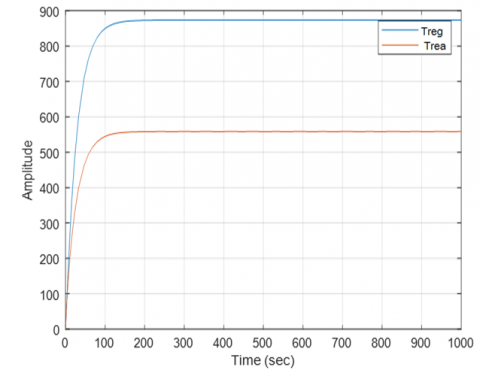
By applying the temperatures of the reactor and regenerator set-points as Treg = 988.5 and Trea = 776, the open loop response is shown in Figure 4.
The open loop response shows that the FCCU is essential to achieve effective operation. The FCCU can maintain peak performance by continuously monitoring and modifying the process variables, this open loop response additionally enables quick adaptation to changes in the composition and quality of the feedstock, ensuring consistent product quality.
Figure 3. Simulink of FCCU model
Figure 4. Open-loop actions of temperature of FCCU's reactor and regenerator
To achieve good product quality and decrease overshoots of exist in the transient responses of the FCCU-controlled system, the NPID control design will be explained in the next paragraph.
The FCCU's nonlinearity has a significant impact on both its stability and overall performance. The system's dynamics behavior is strongly influenced by a number of operational factors; including the feed rate, temperature, and catalyst activity. These variables cause the system to exhibit nonlinearities, which can lead to intricate and unpredictable outcomes. The FCCU's performance and stability must be maximized by comprehending and managing these nonlinearities. So, the use of NPID control in this system is essential which will be explained in the next section.
The NPID controller's basic algorithm is built around an internal nonlinear function. The major purpose is to obtain a wanted result in the plant output where conventional PID could not. As a result, the PID has been recreated using a nonlinear function. Following are some methods for PID improvement [14]:
1. Make the reference input transition in a way that the output can actually follow.
2. Utilizing nonlinear gains.
3. Using a nonlinear differentiator to eliminate noise from the derivative of error (de/dt).
The NPID controller proposes an alternate PID control, that is likewise based on error rather than model-based control. This type of controller has been created to obtain a nonlinear system's response more properly, changing each term with a conventional linear PID controller with a nonlinear function F(e), see Figure 5. The advantages of using nonlinear PID control is to enhance the FCCU's performance and stability. The control system is able to dynamically adapt the changes in feedstock properties. Thanks to its improved adaptability to changing operating conditions. This adaptability is essential for maintaining peak performance because it ensures effective hydrocarbon molecule cracking at a range of feed rates and constituents. As a result, the output of the FCCU is less affected by catalyst deactivation or other external factors thanks to nonlinear PID control). However, the disadvantages are the complexity and nonlinearity in the closed loop system.
Figure 5. Structure of nonlinear PID control [14]
The NPID equation is expressed as follows [14]:
$\begin{gathered}U N P I D=K p F p(e p, \alpha p, \zeta p) +K d F d(e d, \alpha d, \zeta d)+K i F i(e i, \alpha i, \zeta i)\end{gathered}$ (8)
where, Kp, Kd, and Ki are controller gains same that are used in linear PID controller.
The error expressions are: ep is the error (e), ei is the integral of error (∫e dt), and ed is the derivative of error (de/dt).
F is a nonlinear function and expressed as follows [6]:
$F(e, \alpha, \zeta)= \begin{cases}|e|^{\wedge} \alpha \operatorname{sign}(e) & |e|>\zeta \\ \zeta^{\wedge} \alpha-1 & |e| \leq \zeta\end{cases}$ (9)
And
$\operatorname{sign}(e)= \begin{cases}-1, & e<0 \\ 1, & e \geq 0\end{cases}$ (10)
Zeta, in this case, denotes the linear range of the function F, the $\alpha$ parameters are conventionally the error weighting and e is the error signal.
The Firefly algorithm (FA) belongs to the intelligence of a swarm algorithm family, which recently showed impressive performance in handling optimization issues [15]. An FA is a more recent addition to Yang's SI-based algorithms that were first introduced in 2008. Many researchers have begun working with FA since its introduction Initially constrained optimization, multimodal optimization, continuous optimization, and later, real-world problems were all solved using some modified variations. The main optimization’s objective methods are to find the maximum or minimum of mathematical functions, known as objective functions, which may or may not be subject to variable constraints. Optimization algorithms have received increased attention in the fields of engineering and applied mathematics due to their wide range of practical applications.
The interpersonal dynamics of fireflies in a tropical summer sky served as the inspiration for the proposed algorithm. Fireflies use bioluminescence with different flashing patterns to communicate, seek out prayer, and find partners. It is possible to create different meta-heuristic algorithms by modeling nature. In this study, some firefly flashing traits were idealized in order to create an algorithm that was inspired by fireflies. To keep things simple, the following three rules were the only ones applied. Only the three rules listed below were used [16]:
1. Since all fireflies are unisex, they will all be drawn to one another regardless of their sexual orientation.
2. Their brightness directly relates to how attractive they are.
The less intense of two firefly lights will gravitate toward the more intense one. Brightness, which decreases as the distance between fireflies grows, is inversely correlated with attractiveness if none exists.
3. The type of function that needs to be optimized is related to the brightness or light intensity of a firefly. In real life, it is possible to directly relate the brightness of each firefly to the objective function's value.
Following are the randomly selected initial positions of the agents in the search space:
$\begin{gathered}x i j=x i, \min +\operatorname{rand}(x i, \max )-(x i, \min ) \\ i=1,2, \ldots, N\end{gathered}$ (11)
where, xij determines the initial value of the ith variable for the jth agent; (xi, min) and (xi, max) are the minimum and the maximum allowable values for the ith variable. The variation of light intensity and the formulation of attractiveness are two crucial issues in the Firefly algorithm. We can always assume, for the sake of simplicity, that a firefly's attractiveness is determined by its brightness, which is connected to the encoded objective function.Varitions in activity means as (Attractiveness varies with distance). The Pseudo code of Firefly is shown in Table 2.
Table 2. Pseudo code of Firefly algorithm [16]
|
Firefly Algorithm |
|
Start Commencement of the objective function f(x), where x = (x1,..., xd) Create a firefly population of initial size xi (i=1,2,...,n). intensity of light F(xi) establishes Ii at xi. Establish the light-absorbing capacity while (t<Maxgeneration) for i=1: N each and every N fireflies for j=1 In the event that (Ij>Ii), I will all be surrounded by fireflies. If the firefly's level of activity changes, move it from i to j. End if Attractiveness varies with distance. Examine new methods and update the light intensity end for j end for i Ranking the Fireflies to determine which are currently the best End while to analyze the results of the visualization End |
Four NPID controllers were used because of the non-linearity and use of coupling because of the overlap between the reactor and regenerator to manage the temperature of the reactor and the regenerator so that two of the controllers were used for the reactor and two for the regenerator. Figure 6 shows the closed loop-controlled system for regulating the reactor's temperature and the activator.
Figure 6. Simulink of FCCU model with nonlinear PID control
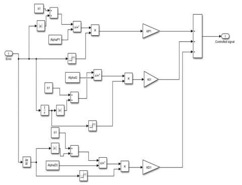
The detailed block diagram of NPID four controllers is shown in Figure 7. The disturbance is provided a step of 50 lph (litter per hour) to Frgc at 1200 sec and removed at 1400 sec.
Figure 7. NPID four controllers
Figure 8. Simulink of NPID control
From Figure 7, each NPID controller is described as shown in Figure 8. Eq. (9) and Eq. (10) described before are used to design each controller.
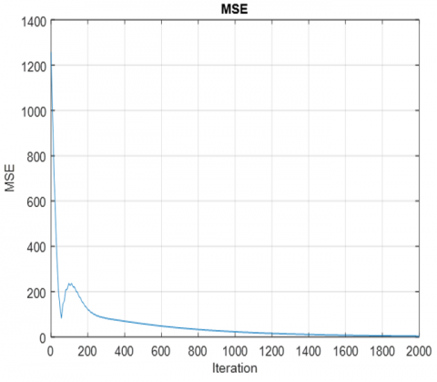
Every NPID control has six parameters which means the best values of twenty- four parameters must be obtained. The controllers' parameters are adjusted using the Firefly algorithm, where $\gamma=1$ in the Firefly algorithm is the light absorption coefficient, Maxgeneration=100 is the most iterations possible, the Number of Fireflies is npop=10, and the objective function is mean square error equation is y=(e12+e22)/2 which e1 and e2 are error1 and error2. After tunning we get the best values, see Table 3.
Table 3. Best gains and parameters of NPID controllers
|
Parameter |
Value |
|
KP1 |
9.8691 |
|
KI1 |
5.9771 |
|
KD1 |
0.994 |
|
AlphaP1 |
8.8987 |
|
AlphaI2 |
1.816 |
|
AlphaD3 |
7.5855 |
|
KP2 |
6.1744 |
|
KI2 |
3.485 |
|
KD2 |
0.8218 |
|
AlphaP12 |
5.5934 |
|
AlphaI22 |
0.2380 |
|
AlphaD32 |
8.3505 |
|
KP3 |
9.3691 |
|
KI3 |
1.004 |
|
KD3 |
6.7552 |
|
AlphaP13 |
0.8875 |
|
AlphaI23 |
1.4864 |
|
AlphaD33 |
4.3923 |
|
KP4 |
3.3986 |
|
KI4 |
7.5541 |
|
KD4 |
6.6215 |
|
AlphaP14 |
9.8780 |
|
AlphaI24 |
0.1408 |
|
AlphaD34 |
8.1380 |
The mean square of error (MSE) fitness function is used to measure the best values of controllers. Figure 9 depicts the variation MSE with respect to iterations for the best results obtained in Table 3.
Figure 9. Mean square of error for Firefly algorithm
The results shown above were expected with the effect of chattering and the application of the FA has demonstrated to be a successful method for improving the unit's general functionality and performance. Also, the disturbance, which is the change in feed composition happen, may cause changes in process parameters and have an impact on the FCCU's overall performance and stability. Chattering refers to rapid and uncontrolled fluctuations in key variables such as temperature, flow rates. This chattering can be minimized by modifying the controller into hybrid intelligent-nonlinear control.
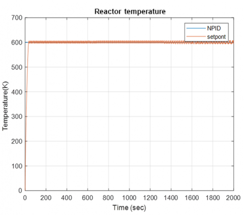
By applying the set point Trea=600, the result is shown in Figure 10.
Figure 10. Time response of reactor temperature controlled system
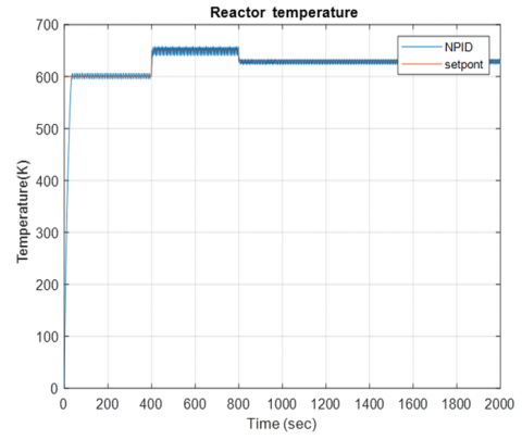
When applying a variable set point with a range of Trea (600K-800K), the result is shown in Figure 11.
Figure 11. Time response of reactor temperature controlled system variable step
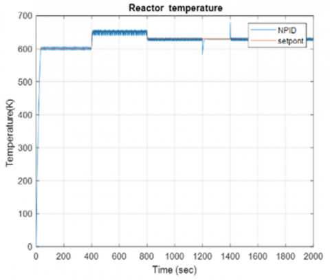
By applying variable set point with a range of Trea (600K-800K) and the effect of disturbance represneted as a step of 50 lph (litter per hour) to Frgc (flow rate of regenerated catalyst), the response of reactor temperature is shown in Figure 12.
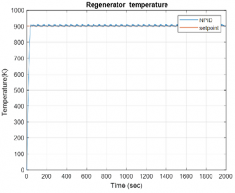
When applying the set point Treg=900K, the result is shown in Figure 13.
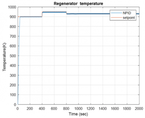
By applying variable set point with a range of Treg (900K-1000K) and disturbance effect which provided with a step of 50 lph (litter per hour) to Frgc (Flow regenerated catalyst), the response of regenerator temperature is shown in Figure 14.
By applying variable set point with a range of Treg (900K-1000K) and disturbance effect which provided with a step of 50 lph (litter per hour) to Frgc (Flow rate of regenerated catalyst) the response is shown in Figure 15.
Figure 12. Time response of reactor temperature controlled system with disruption
Figure 13. Response of regenerator temperature controlled system
Figure 14. Time response of regenerator temperature controlled system variable step
Figure 15. Time response of regenerator temperature controlled system with disturbance
The error1 signal is shown in Figure 16.
Figure 16. Time response of error reactor temperature controlled system
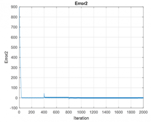
The error2 signal is shown in Figure 17.
Figure 17. Time response of error regenerator temperature controlled system
In this paper, nonlinear four PID controllers have been designed for the FCCU. In order to adjust the controllers' parameters, the Firefly algorithm was used. From the simulation results, it is inferred that the closed loop of the FCCU is stable. By comparing results with other published paper [13], the reduction of overshoot in the response of the reactor temperature by 90% and the regenerator temperature by 85% as compared with reference No. 13. The overshoot of reactor temperature is 0.239%, and the rise time is 24.87631 sec. For the regenerator, the overshoot is 0.703% and the rise time is 25.636 sec. The limitation is the chattering in the closed loop system response. This exists because of the nonlinearity in the model.
As a future work. a hybrid Intelligent-Nonlinear control consists of fuzzy logic and nonlinear PID controllers is used to avoid chattering.
I would like to acknowledge and give my warmest thanks to my supervisor, Dr. Mohammed Y. Hassan, whose guidance and support have been instrumental in the completion of this work. And his direction and advice were pivotal in bringing my project to fruition.
|
Frgc |
Mass flow rate of regenerated catalyst, Kg/sec |
|
Ff |
Mass flow rate of feed, Kg/sec |
|
Fs |
Mass flow rate of steam, Kg/sec |
|
Fp |
Mass flow rate of the product, Kg/sec |
|
Fsc |
Mass flow rate of spent catalyst, Kg/sec |
|
Fai |
Mass flow rate of air, Kg/sec |
|
Ffl |
Mass flow rate of flue gases, Kg/sec |
|
Cprgc |
Heat capacity of regenerated catalyst, KJ/Kg.K |
|
Cpf |
Heat capacity of feed, KJ/Kg.K |
|
Cpp |
Heat capacity of the product, KJ/Kg.K |
|
Cpsc |
Heat capacity of spent catalyst, KJ/Kg.K |
|
Cpp |
Heat capacity of the product, KJ/Kg.K |
|
Cpai |
Heat capacity of air, KJ/Kg.K |
|
Cpfl |
Heat capacity of flue gases, KJ/Kg.K |
|
Cprgc |
Heat capacity of regenerated catalyst, KJ/Kg.K |
|
Tf |
Temperature of feed, K |
|
Trea |
Temperature of the reactor, K |
|
Tai |
Temperature of air, K |
|
Treg |
Temperature of regenerator, K |
|
Hs |
Heat of steam, K |
|
Hrea |
Heat of reaction, K |
|
Hco |
Heat of combustion, K |
|
Mp |
Mass of product, Kg |
|
Msc |
Mass of spent catalyst, Kg |
|
Mrgc |
Mass of regenerated catalyst, Kg |
|
Mfl |
Mass of flue gases, Kg |
|
KP |
Proportional control gain, without units |
|
Kd |
Derivative control gain, without units |
|
Ki |
Integral control gain, without units |
|
ep |
Proportional error, without units |
|
ed |
Derivative error, without units |
|
ei |
Integral error, without units |
|
Fp |
Nonlinear function of proportional control, without units |
|
Fd |
Nonlinear function of derivative control, without units |
|
Fi |
Nonlinear function of integral control, without units |
|
xi |
Initial population of fireflies, without units |
|
n |
Number of fireflies, without units |
|
Greek symbols |
|
|
$\gamma$ |
Light absorption coefficient |
|
ζ |
Linear range of function |
|
Ii |
Light intensity |
|
α |
Error weighting |
|
Subscripts |
|
|
FCCU |
Fluid Catalytic Cracking Unit |
|
PID |
Proportional–Integral–Derivative |
|
NPID |
Nonlinear Proportional–Integral–Derivative |
|
FA |
Firefly Algorithm |
|
MSE |
Mean Square Error |
[1] Shakoor, Z.M. (2010). Estimation of Kinetic Parameters of Complex Reactions by MATLAB Software. University of Technology, Iraq.
[2] Chao, C.T., Sutarna, N., Chiou, J.S., Wang, C.J. (2019). An optimal fuzzy PID controller design based on conventional PID control and nonlinear factors. Applied Sciences, 9(6): 1224. https://doi.org/10.3390/app9061224
[3] Tahir, T.A., Al-Samarraie, S.A. (2021). The application of extremum seeking algorithms in PID tuning for continuous stirred tank reactor. International Review of Automatic Control (IREACO), 14(1): 20135. https://doi.org/10.15866/ireaco.v14i1.20135
[4] Jassim, A.A., Karam, E.H., E Ali, M.M. (2023). Design of optimal PID controller for electric vehicle based on particle swarm and multi-verse optimization algorithms. Engineering and Technology Journal, 41(2): 446-455. https://doi.org/10.30684/etj.2023.135587.1279
[5] Anbumalar, P., Janani, J., Sriram, Uwise. (2015). Non-linear PID control of ph process. International Conference on Emerging Trends in Engineering Research.
[6] Valluru, S.K., Singh, M. (2018). Performance investigations of APSO tuned linear and nonlinear PID controllers for a nonlinear dynamical system. Journal of Electrical Systems and Information Technology, 5(3): 442-452. https://doi.org/10.1016/j.jesit.2018.02.001
[7] Su, Y.X., Duan, B.Y., Zheng, C.H. (2004). Nonlinear PID control of a six-DOF parallel manipulator. IEEE Proceedings-Control Theory and Applications, 151(1): 95-102. https://doi.org/10.1049/ip-cta:20030967
[8] Izadbakhsh, A., Kheirkhahan, P. (2018). Nonlinear PID control of electrical flexible joint robots-Theory and experimental verification. In 2018 IEEE International Conference on Industrial Technology (ICIT), Lyon, France, pp. 250-255. https://doi.org/10.1109/ICIT.2018.8352185
[9] Shamseldin, M.A., Sallam, M., Bassiuny, A.M., Ghany, A.A. (2018). Real-time implementation of an enhanced nonlinear PID controller based on harmony search for one-stage servomechanism system. Journal of Mechanical Engineering and Sciences, 12(4): 4161-4179. https://doi.org/10.15282/jmes.12.4.2018.13.0359
[10] Yang, F., Dai, C., Tang, J., Xuan, J., Cao, J. (2020). A hybrid deep learning and mechanistic kinetics model for the prediction of fluid catalytic cracking performance. Chemical Engineering Research and Design, 155: 202-210. https://doi.org/10.1016/j.cherd.2020.01.013
[11] Jia, C., Rohani, S., Jutan, A. (2003). FCC unit modeling, identification and model predictive control, a simulation study. Chemical Engineering and Processing: Process Intensification, 42(4): 311-325. https://doi.org/10.1016/S0255-2701(02)00055-7
[12] AL-Niami, S.A., Mehdi, F.A. (2021). Decoupling control of a FCC unit using fuzzy logic. University of Technology, Iraq.
[13] Brijet, Z., Bharathi, N. (2021). Design of type-2 fuzzy logic controller for fluid catalytic cracking unit. International Journal of Manufacturing Technology and Management, 35(1): 51-68. https://doi.org/10.1504/IJMTM.2021.114700
[14] Karthika, V., Brijet, Z., Bharathi, N. (2012). Design of optimal controller for fluid catalytic cracking unit. Procedia Engineering, 38: 1150-1160. https://doi.org/10.1016/j.proeng.2012.06.146
[15] Fister Jr, I., Perc, M., Kamal, S.M., Fister, I. (2015). A review of chaos-based firefly algorithms: Perspectives and research challenges. Applied Mathematics and Computation, 252: 155-165. https://doi.org/10.1016/j.amc.2014.12.006
[16] Gandomi, A.H., Yang, X.S., Talatahari, S., Alavi, A.H. (2013). Firefly algorithm with chaos. Communications in Nonlinear Science and Numerical Simulation, 18(1): 89-98. https://doi.org/10.1016/j.cnsns.2012.06.009