Ali Mahmood![]() | Mohammed Almaged
| Mohammed Almaged![]() | Yazen Hudhaifa Shakir Alnema
| Yazen Hudhaifa Shakir Alnema![]() | Mohanad N. Noaman*
| Mohanad N. Noaman*![]()
© 2023 IIETA. This article is published by IIETA and is licensed under the CC BY 4.0 license (http://creativecommons.org/licenses/by/4.0/).
OPEN ACCESS
This paper shows the modelling and implementation of an adaptive cruise control (ACC) system for intelligent vehicles using fuzzy logic control approach. Initially, MATLAB Simulink is utilized to design an advanced vehicle model that takes into account most of the vehicle parameters using Simscape Driveline toolkit. Then, the fuzzy logic toolbox in MATLAB Simulink is introduced for designing and simulation of the fuzzy logic system. The proposed ACC algorithm functions in two different modes, the distance and velocity modes, based on the speed of the moving vehicle and the vehicle ahead. In distance control mode, the vehicle measures the actual distance to the vehicle ahead and compares it to the safe distance. If the measured distance is larger than the safe distance, the setpoint will be the safe distance and the system will work on maintaining the actual distance equal or greater than the safe distance. However, in speed control mode, the controller will operate according to the set speed adjusted by the driver given that the safe distance condition is met. This gives the vehicle the ability to make decisions relaying on both the set speed by the driver and the actual distance to the upfront objects. It is worth to mention that only a single controller is employed for both modes. According to MATLAB simulations, it is proven that the designed ACC algorithm using fuzzy logic controller is capable of retaining the vehicle in desired constraints as well as achieving satisfactory results owing to the simplicity of the proposed approach. The findings further demonstrate that the system have actually no overshoot with absolutely null steady state error while responding to the given speed with quite swift rising and settling times. However, there happen to be some rapid fluctuations in the throttle and brake values especially when the actual distance suddenly drops below the desired safe distance which may cause some driving inconvenience to the passengers.
fuzzy logic controller, adaptive cruise control, MATLAB Simulink, autonomous vehicles, Simscape vehicle model
The drivers’ requirements nowadays have increased to ensure safety and comfort through driving assistant systems. The automation in these systems has been developed as well which is shortly called AD as abbreviation of Automated Driving. The structure or architecture of this automation can be classified according to the following; perception the environment, motion control and behavior planning [1]. Adaptive cruise control (ACC) is the updated version of the traditional cruise control (CC) system which has many advantages over it. For instance, the ACC maintains a safety distance in addition to holing constant speed when it is activated. This can be done by adding measurement sensor such as smart cameras to sense the vehicle surroundings. ACC is one of the automated systems that assist the drivers to manage their vehicles’ longitudinal control when driving in motorway. The control action will regulate each of the accelerator, the engine powertrain unit and finally brakes or brake pads to keep the desired distance to automobile ahead. The main purpose of the ACC behind keeping an acceptable distance between two vehicles is to optimize the roadway capacity and avoid collision as well as fuel economy that leads to fewer emissions accordingly [2, 3].
A number of previous studies has revealed the control approaches or techniques on adaptive cruise. Reference [4] employ the principle of fuzzy logic control as Proportional-Derivative (PD) and then plus Integral (I) controller to be PD plus I not as classical PID. This technique multiplies the error with an appropriate or tuned proportional gain and differentiated it then sum the result and make integral to obtain the control signal that drives the fuzzy logic controller (FLC). The fitness functions used for this implementation are (IAE and ISE) that analysis the integral error in two cases to make an evolution of the results from the simulation. The author focused on how to reduce the integral windup and repress derivative kick. Reference [5] makes investigations and studies the performance of the ACC with respect to the driver’s anticipation and expectation.
Designing fuzzy with PD controller scheme attracts the attention of many researchers recently especially for affine nonlinear systems that are linear in the input to ensure both kinds of stabilities global asymptotic and semi-global asymptotic. Adaptive fuzzy with H-infinity control theory in an indirect implementation used in the study [6] which applied, on perturbed uncertain nonlinear systems. The PD controller is independent of both adaptive fuzzy and perturbation control laws. Affine nonlinear systems also controlled via a combination of adaptive neural network with PD to ensure that semi-global asymptotic stability within the acceptable range [7]. In the study [8], fuzzy with PD controller employed to achieve global asymptotic stabilization for non-linear systems. While in the studies [9, 10] fuzzy with PD plus I which is integral the error after summing point where the simulation graphs show the performance of this implementation compared with linear PID.
Keeping safe and measured distances as set point desired for the vehicle by ACC assistance occurs through breaking and throttle control. These two control factors can play a vital role in longitudinal dynamics vehicle to reduce and increase the required meters between two automobiles. The smooth control coordination between brake and accelerator or throttle has been realized in the studies [11, 12]. In this literature, the braking system mathematically simplified to be first order plant. The sequence of the proposed approach supposes that there are upper and lower controllers. The former calculates the acceleration while the latter gives the commands according to the output signal of the first controller to the brake and throttles for non-linear longitudinal model.
Finding the solution of a longitudinal direction control for motion of autonomous vehicles can be coordinated via the means of communication between CC and ACC. This means that the space and speed control of the mobile robot are realized and achieved by ACC [13]. From this aspect, higher levels in terms of safety and comfort that leads to less energy consumption in autonomous cars is reached by inserting CACC which is abbreviation of cooperative adaptive cruise control [14]. CACC is used for vehicle-to-vehicle communication approach in electric cars such as Q-Car with another one while the ACC is designed for the first stage of distance control in electric autonomous car [15].
The work done in this paper is an extend to what have been designed in previous paper which is ACC of a Simscape vehicle model with two PID controllers [16]. The main challenge in this paper is to control both break and throttle utilizing only a single controller. Thus, the main contribution of this paper is designing a PD fuzzy logic controller with two inputs which are the error and the change in error and two outputs from the Mamdani FLC, which are throttle and break. Speed and distance controllers in each state one controller be online by switching mode in Simulink platform. The plant of the vehicle has been designed using Simscape library in MATLAB. the rest of the sections will be ACC algorithm explanation, controller design and simulation results.
Most of vehicle kinematic and longitudinal models are represented in ordinary differential equations or state space representations that mainly takes into account basic vehicle parameters’ such as mass, drag force, road resistance, speed and acceleration [17, 18]. The more parameters added to the modelling highly increases the complexity of the system making it highly difficult to derive and linearize. Therefore, to design an accurate adaptive cruise control, more advanced modeling techniques are required that consider most of the vehicle parameters such as engine performance, power train design, vehicle body specification, etc. Therefore, MATLAB Simulink was utilized to design a more realistic vehicle model that includes engine block, drivetrain unit, and vehicle chassis specification using Simscape Driveline toolkit. Furthermore, the mathematical derivation of vehicles models is quite complex and required great knowledge in ordinary differential and algebraic equations. However, Simscape employs graphical modeling approach that inherently implement the exact modelling equations but easier to understand and operate.
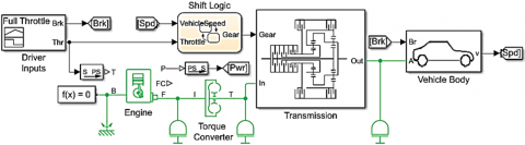
According to the designed model shown in Figure 1, the torque produced by the engine based on the driver throttle input is delivered to the torque converter, that subsequently transfers the power to the gearbox. The gearbox selects the appropriate gear through the shift logic depending on the amount of throttle applied and the speed of the vehicle. The vehicle is equipped with a rear wheel driving system (RWD) which receives an even shared of the acquired torque from the differential that is connected to the gearbox. All Simscape blocks including engine, torque converter, gearbox and vehicle body must be connected into a physical network while data entries of these blocks can be modified from the block dialog boxes. In overall, the inputs of the entire vehicle system are throttler and brake while the output are speed and power. The design procedure of the complete vehicle dynamic model is described in great details in the study [19].
Figure 1. Simscape vehicle model
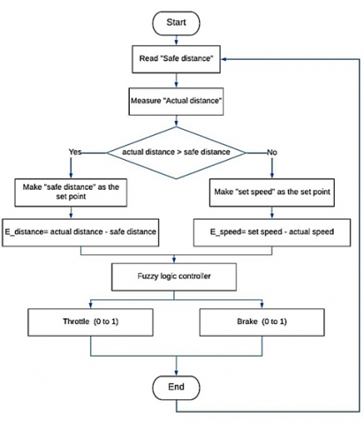
The main difference between cruise control (CC) and adaptive cruise control (ACC) is that the ACC system can sense the environment and determine upfront vehicle/object’s distance. This gives the vehicle the ability to make decisions relaying on both the driver set speed and the exact distance to the leading objects. The first step in the proposed ACC algorithm is to measure the actual distance to the vehicle ahead and compare it to the safe distance. If the measured distance is larger than the safe distance, the ACC will work as a traditional CC whereas the set point for the controller will be the speed set by the driver. Otherwise, the setpoint will be the safe distance and the system will work on maintain the current distance equal or greater than the predefined safety distance. The importance of the proposed approach is that it employs one controller only for both speed and distance regulation. The only modification needed is to multiply the error of the distance by a factor to match the range of speed error. Implementing the algorithm in this way makes the design procedure much easier whereas the entire algorithm can be divided into two sub algorithms. The first algorithm is called when the actual distance is less than the safe distance. In this case, the algorithm works exactly as cruise control (CC) system. Otherwise, the second sub algorithm will be employed and the system will focus mainly on monitoring the safe distance. The entire algorithm is summarized in Figure 2.
whereas,
$\mathrm{E}$ distance $=\mathrm{d}$ safe $-\mathrm{d}$ actual (1)
$\mathrm{E}$ speed $=\mathrm{s}$ desired $-\mathrm{s}$ actual (2)
The main challenge will be the switching between the two sub-algorithms as it should be smooth and does not have a sharp change in the vehicle’s true speed. The other challenge is the value of throttle and brake where they should not be applied at the same time. To solve this problem, two selectors will be used for throttle and brake. If the actual speed is greater than the desired speed within a specific limit, the action will be reducing the value of the throttle without pressing on the brake pedal. Else, the decision will be pressing on the brake after release the pressure on the throttle pedal.
Figure 2. Flowchart of ACC algorithm
The mechanism of fuzzy logic depends on rules which are a list of if-then statements. The main characteristic that differs fuzzy logic from Boolean logic is that its value has a membership function from 0 to 1 while Boolean logic is either 0 or 1.
The main advantage of fuzzy logic controller over other controllers like PID controller it can make use of the human experience for its design where it uses linguistic expressions rather than using mathematical designing methods. Also, the main characteristic that made the choice of the fuzzy logic controller over other controllers it can work with nonlinear systems without linearizing them since other controllers such as PID and LQR controllers work only with linear systems. This will give more realistic results over using linearized model of the system.
The fuzzy logic toolbox provided by MATLAB is used for analyzing, designing, and simulation of the system based on the fuzzy logic. The first step in designing fuzzy controller is to choose the inputs and outputs of the controller. In this particular system, the inputs are the error and the change in error of either distance or speed depending on the applied sub algorithm. However, the controlled output variables are the throttle and brake. The next step is to enter the type of the membership function and the rules that fuzzy controller implement.
It is important to say that there is no standard procedure for choosing the membership function and it usually depends on the designer experience. However, there are some considerations could be used for the selection of these membership functions.
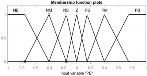
A triangular membership functions has been chosen for the both inputs with a trapezoidal function on both end of the inputs to cover the extreme inputs values. The rationale for this choice is multifaceted. First and foremost, it prioritizes simplicity. Triangular and trapezoidal functions are relatively easy to define and use since they can be characterized by a limited number of parameters. Second, it emphasizes robustness, as these two functions can handle a broad spectrum of input values without distorting the information. Lastly, it highlights interpretability, signifying that they are intuitive and easily understandable by humans.
On the other hand, a gaussian membership function is selected for the throttle and brake outputs along with a trapezoidal function on the extreme end of the output.
The rationale behind selecting Gaussian membership functions is twofold. First, Gaussian membership functions enable smooth and continuous transitions between linguistic values. Second, they are well-suited for modeling uncertainty and capturing the probabilistic nature of real-world processes.
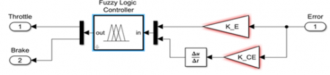
The block diagram of the subsystem of the fuzzy logic controller is shown in Figure 3.
Figure 3. Block diagram of fuzzy logic controller
(a) Membership function of input error (E)
(b) Membership function of input change in error (CE)
Figure 4. Membership functions for error signals
(a) Membership function of output throttle (T)
(b) Membership function of output brake (B)
Figure 5. Membership functions of brake and throttle
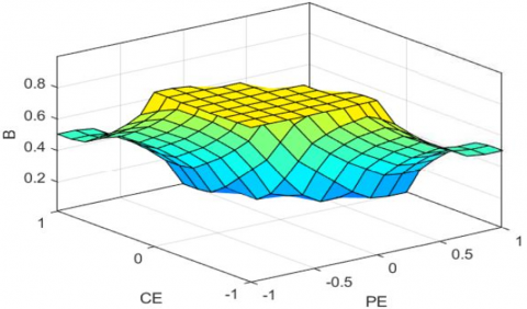
The membership function of the inputs and outputs are shown in Figures 4 and 5 respectively. The relationship between the inputs and output variables based on the selected membership functions and applied rules is shown in Figure 6 and Figure 7 respectively.
Figure 6. Control surface of the throttle control surface of the fuzzy controller
Figure 7. Control surface of the brake
Table 1 displays the rules employed in this paper. Given that both the inputs and output are divided into seven membership functions, a total of forty-nine rules are necessary to encompass all potential scenarios.
The fundamental component of a fuzzy controller is the rule base, which comprises a set of linguistic rules. Each rule adheres to an 'if-then' structure, with conditions specified in the antecedent ('if' part) and actions in the consequent ('then' part). To represent the system's inputs and outputs, linguistic variables are selected and described through membership functions defining their fuzzy sets. In this paper, the linguistic terms used for inputs and outputs include:
NB: Negative Big
NM: Negative Medium
NS: Negative Small
Z: Zero
PS: Positive Small
PM: Positive Medium
PB: Positive Big.
The next step involves constructing rules using logical operators, such as AND, OR, and NOT. In this paper, we exclusively utilize the AND operator. The final step is to formulate the rules based on knowledge and expertise.
Table 1. Fuzzy rules for (49) rules
|
E CE |
NB |
NM |
NS |
ZR |
PS |
PM |
PB |
|
NB |
NB |
NB |
NB |
NB |
NS |
ZR |
PS |
|
NM |
NB |
NB |
NB |
NM |
NS |
ZR |
PS |
|
NS |
NB |
NB |
NM |
NS |
ZR |
PS |
PM |
|
ZR |
NB |
NM |
NS |
ZR |
PS |
PM |
PB |
|
PS |
NM |
NS |
ZR |
PS |
PM |
PB |
PB |
|
PM |
NS |
ZR |
PS |
PM |
PB |
PB |
PB |
|
PB |
ZR |
PS |
PM |
PB |
PB |
PB |
PB |
5.1 Simulation
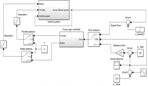
MATLAB Simulink is utilized to design the entire adaptive cruise control system shown in the Figure 8. The block diagram of the system is consisted of three sub systems including the vehicle model, fuzzy logic controller and error selector sub system. The vehicle model is categorized into four main components: the torque converter, shift logic, transmission, and the vehicle body. The inputs required for this model include the throttle and brake inputs. Based on these inputs, the model generates the output, which corresponds to the vehicle speed. For the fuzzy logic controller system, the inputs are the error and the change in error of either speed or distance as shown in Eqs. (1) and (2).
Figure 8. Complete adaptive cruise control system
The error selector subsystem operates based on the disparity between the actual distance and the safe distance. If the actual distance exceeds the safe distance, it chooses the speed error and forwards it to the controller. Otherwise, it transmits the distance error.
Instead of using two controllers for speed control and distance control which makes it hard to simulate and implement, a selector control switch is used with only one controller. Control switch has control port which will be used to select between the error of distance and the error of speed based on the difference between the actual distance and the safe distance. When the actual distance exceeds the safe distance, it chooses the speed error and forwards it to the controller. Alternatively, if the actual distance is less than the safe distance, it transmits the distance error.
Practically, once the vehicle’s true speed is little higher than the preferred speed, the driver just stops pressing on the pedal (without pressing on the brake pedal). For this reason, other two selectors have been used for the throttle and brake. The role of these selectors is applied when the change in speed is small, the system will release the throttle pedal without pressing the brake pedal. Otherwise, the system will activate the brake pedal while releasing the throttle pedal.
5.2 Results
The system is tested based on two cases scenarios. The first case scenario when there is widely open space in front of the vehicle and hence the true distance is always greater than the necessary safe distance, it works as a conventional cruise control system (CC) as shown in Figure 9. In this case, the error will depend only on the speed of the vehicle. It is important to notice the values of the throttle and brake with every change, Figure 10 shows this change. In the same time, the error selector is choosing between the speed-error and distance-error as shown in Figure 11. When the required clearance between the two vehicles is greater than the true distance, the error that to the controller will be the speed-error for the whole time.
Figure 9. Simulated speed tracking of cruise controller
Figure 10. Throttle and brake values for the first case
Figure 11. Error selector for first case
In terms of the system's response (the actual vehicle's speed), it exhibits no overshoot and no steady-state error. The rise time and settling time for increasing the speed from one value to another depend primarily on two factors: the magnitude of the change and the speed values. For instance, when the speed is increased from 60mph to 80mph, the rise time is 17 seconds, and the settling time is 20 seconds. Another example can be seen when the speed is decreased from 80mph to 50mph, where the rise time is 10 seconds, and the settling time is 14 seconds. It's important to note that the speed reduction occurs at a higher rate, ensuring the controller's ability to rapidly reduce speed and bring the vehicle to a stop as quickly as possible.
Figure 12. Simulated speed tracking of adaptive cruise controller
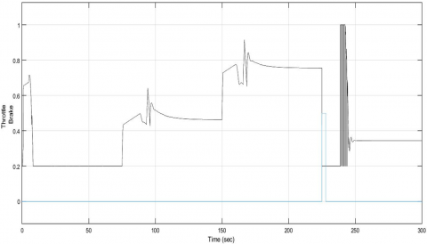
Figure 13. Throttle and brake values for the second case
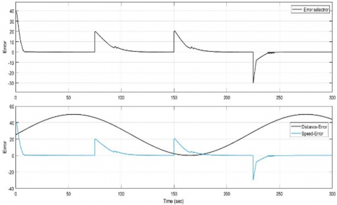
Figure 14. Error selector for second case
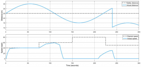
Figure 15. Simulated speed tracking of adaptive cruise controller with disturbance at t=240 sec
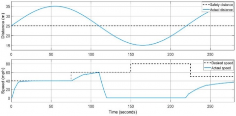
The second tested case is when there is a vehicle ahead driven in lower speed than the set speed by the driver while the true distance is equal to the safety clearance as shown in Figure 12. The System will work as an adaptive cruise control system. In this case, the error will depend on the safe distance of the vehicle ahead. In this case, the throttle and brake values are as well as the error selector are shown in Figures 13 and 14 respectively. It is important to notice the value of the error coming from the error selector where it chooses between the speed-error and distance-error. To check the robustness of the designed controller, the actual distance is sharply reduced at t=240 sec. In this case, the distance error becomes very high. As a result, the controller will attempt to rapidly reduce it by significantly decreasing the driving speed of the vehicle, as illustrated in Figure 15. The speed is reduced from 30mph to 0mph in just 6 seconds.
In this work, a fuzzy logic controller has been designed and simulated for adaptive cruise control. Standard FLC has not produced the desired response especially when the system having continuously changing driving conditions. However, integrating PD with FLC Controller has yielded much better results. In the context of vehicle modeling, the MATLAB Simscape library facilitates the development of a visual model representing a physical vehicle. This model emulates real-world vehicle dynamics, providing a more accurate representation compared to mathematical models, which often rely on simplifications and necessitate linearization to approximate behavior. The most importance feature of this work was utilizing a single fuzzy controller for both, throttle and brake. The gain of the PD FLC controller has been tuned manually which can be improved as a future work using an efficient optimization technique. The designed system is adaptive cruise so that the set point of the controller will be either speed or distance. If the actual distance is greater than the calculated clearance, the adaptive cruise control will work as traditional cruise control and the set point will be the set speed adjusted by the driver. Otherwise, the set point will be the safe instance and the vehicle will try to keep the true distance equal or more than the safe distance and neglecting the prefered speed set by the driver. To assess the effectiveness and reliability of the proposed fuzzy controller, several simulations have been made for different scenarios. The controller shows accepted results whereas the vehicle’s current speed always tracks the set speed while keeping the actual distance equal or greater than the safe distance.
[1] Li, X., Lin, K.Y., Meng, M., Li, X., Li, L., Hong, Y., Chen, J. (2021). Composition and application of current advanced driving assistance system: A review. arXiv Preprint arXiv: 2105.12348. https://doi.org/10.48550/arXiv.2105.12348
[2] Marsden, G., McDonald, M., Brackstone, M. (2001). Towards an understanding of adaptive cruise control. Transportation Research Part C: Emerging Technologies, 9(1): 33-51. https://doi.org/10.1016/S0968-090X(00)00022-X
[3] Dey, K.C., Yan, L., Wang, X., Wang, Y., Shen, H., Chowdhury, M., Yu L, Qiu C, Soundararaj, V. (2015). A review of communication, driver characteristics, and controls aspects of cooperative adaptive cruise control (CACC). IEEE Transactions on Intelligent Transportation Systems, 17(2): 491-509. https://doi.org/10.1109/TITS.2015.2483063
[4] Prabhakar, G., Selvaperumal, S., Nedumal Pugazhenthi, P. (2019). Fuzzy PD plus I control-based adaptive cruise control system in simulation and real-time environment. IETE Journal of Research, 65(1): 69-79. https://doi.org/10.1080/03772063.2017.1407269
[5] Zheng, P., McDonald, M. (2005). Manual vs. adaptive cruise control-Can driver’s expectation be matched?. Transportation Research Part C: Emerging Technologies, 13(5-6): 421-431. https://doi.org/10.1016/j.trc.2005.05.001
[6] Pan, Y., Er, M.J., Sun, T., Xu, B., Yu, H. (2017). Adaptive fuzzy PD control with stable H∞ tracking guarantee. Neurocomputing, 237: 71-78. https://doi.org/10.1016/j.neucom.2016.08.091
[7] Pan, Y., Yu, H., Er, M.J. (2014). Adaptive neural PD control with semiglobal asymptotic stabilization guarantee. IEEE Transactions on Neural Networks and Learning Systems, 25(12): 2264-2274. https://doi.org/10.1109/TNNLS.2014.2308571
[8] Bhushan, B., Jha, N., Devra, S., Pillai, S.S. (2014). Performance analysis of PID and Fuzzy PD+I controller on nonlinear systems. In 2014 IEEE International Advance Computing Conference (IACC), pp. 1195-1200. https://doi.org/10.1109/IAdCC.2014.6779497
[9] Qiu, C. (2014). A design of automobile cruise control system based on fuzzy PID. In 2014 International Conference on Information Science, Electronics and Electrical Engineering, IEEE, 1: 450-452. https://doi.org/10.1109/InfoSEEE.2014.6948151
[10] Lee, J.Y., So, H.R., Lee, Y.H., Oh, S.J., Jin, G.G., So, M.O. (2015). Fuzzy PD plus I controller of a CSTR for temperature control. Journal of Advanced Marine Engineering and Technology (JAMET), 39(5): 563-569. http://dx.doi.org/10.5916/jkosme.2015.39.5.563
[11] Luu, D.L., Lupu, C. (2019). Dynamics model and design for adaptive cruise control vehicles. In 2019 22nd International Conference on Control Systems and Computer Science (CSCS), IEEE, pp. 12-17. https://doi.org/10.1109/CSCS.2019.00010
[12] Luu, D.L., Lupu, C., Alshareefi, H., Pham, H.T. (2021). Coordinated throttle and brake control for adaptive cruise control strategy design. In 2021 23rd International Conference on Control Systems and Computer Science (CSCS), IEEE, pp. 9-14. https://doi.org/10.1109/CSCS52396.2021.00009
[13] Luu, D.L., Lupu, C., Cristian, I. (2021). Speed control and spacing control for autonomous mobile robot platform equipped with infrared sensors. In 2021 16th International Conference on Engineering of Modern Electric Systems (EMES), IEEE, pp. 1-4. https://doi.org/10.1109/EMES52337.2021.9484140
[14] Acquarone, M., Borneo, A., Misul, D.A. (2022). Acceleration control strategy for Battery Electric Vehicle based on deep reinforcement learning in V2V driving. In 2022 IEEE Transportation Electrification Conference & Expo (ITEC), pp. 202-207. https://doi.org/10.1109/ITEC53557.2022.9813785
[15] Ke, H., Mozaffari, S., Alirezaee, S., Saif, M. (2022). Cooperative adaptive cruise control using vehicle-to-vehicle communication and deep learning. In 2022 IEEE Intelligent Vehicles Symposium (IV), pp. 435-440. https://doi.org/10.1109/IV51971.2022.9827148
[16] Mahmood, A.K., Almaged, M., Noaman, M.N., Alnema, Y.H.S. (2021). Adaptive cruise control of a simscape driveline vehicle model using PID controller. Journal of Engineering Science and Technology, 16(1): 681-695.
[17] Takahama, T., Akasaka, D. (2018). Model predictive control approach to design practical adaptive cruise control for traffic jam. International Journal of Automotive Engineering, 9(3): 99-104. https://doi.org/10.20485/jsaeijae.9.3_99
[18] Luu, D.L., Lupu, C., Van Nguyen, T. (2019). Design and simulation implementation for adaptive cruise control systems of vehicles. In 2019 22nd International Conference on Control Systems and Computer Science (CSCS), IEEE, pp. 1-6. https://doi.org/10.1109/CSCS.2019.00008
[19] Pan, Y., Yu, H., Sun, T. (2014). Global asymptotic stabilization using adaptive fuzzy PD control. IEEE Transactions on Cybernetics, 45(3): 574-582.