Vuong Dang Quoc*![]() | Dinh Bui Minh
| Dinh Bui Minh![]() | Hien Nguyen Thi Minh | Bao Doan Thanh
| Hien Nguyen Thi Minh | Bao Doan Thanh![]()
© 2023 IIETA. This article is published by IIETA and is licensed under the CC BY 4.0 license (http://creativecommons.org/licenses/by/4.0/).
OPEN ACCESS
The objective of this paper is to compare and analyze two types of electric motors, an electrically excited synchronous motor (EESM) and an interior permanent magnet (IPM) motor for an electric vehicle (EV) application. In order to achieve the objective, a comparative analysis of the EESM and IPM motors is presented via the analytic model and finite element method to examine and simulate the torque and power performances as well as their efficiency maps of both motors based on a Volkswagen ID.3 2020 reference model. The analysis takes into account the same machine size and power inverter for both motors. The examination indicates that the EESM achieved better torque and power but lower efficiency, especially at high speeds. The EESM requires flux weakening for a wider constant power range. The EESM can be a low-cost alternative given its adjustable excitation. The EESM has achieved a wider speed range but lower peak efficiency than the IPM. Findings inform optimal propulsion system design for EVs. This research provides valuable insights for automakers seeking to optimize drivetrain performance by selecting suitable electric motor options. The findings contribute to the advancement of next-generation propulsion systems for electric mobility.
electric vehicles, synchronous motors, permanent magnet motors, electrically excited motors, performance analysis, cogging torque
This research presents two types of electric motors, an electrically excited synchronous motor (EESM) and an interior permanent magnet (IPM) motor, for an electric vehicle (EV) application based on a Volkswagen ID.3 2020 reference model. The IPM motor is well known for its high efficiency, high torque density, and extended speed range due to magnets placed inside the rotor, but the performance of this motor was affected by the rotor topologies as proposed in the study [1]. This paper presented a way to reduce the torque ripple and electromagnetic vibration via a change of the new rotor configuration for V-shaped rotor of the IPM. In the studies [2, 3], an enhanced skewing technique and a novel dual-rotor axial-gap flux-switching permanent-magnet machine were presented to effectively reduce both cogging torque and electromagnetic torque ripple. In the study [4], a paper introduced a topology utilizing a homopolar machine configuration. The design incorporated consequent-pole permanent magnet (PM) poles positioned on the stator surface, while the DC field winding was wound around the mover yoke. The paper [5] presented a novel design for a hybrid excitation synchronous machine in which a magnetic shunting rotor to enhance torque density and flux regulation capability, particularly in the EV traction applications.
In the study [6], the authors redesigned and improved each topology to meet new design requirements based on the same constraints, and evaluate the motors for motor performance, torque segregation, demagnetization, mechanical stress, and radial forces. A new approach for designing permanent magnet synchronous motors (PMSMs) by optimizing the PM structure to achieve better performance and lower manufacturing costs [7]. The studies [8, 9] provided a valuable contribution to the fields of IPM machine via the finite element analysis. The results could have significant practical implications for the development of high-performance traction systems. The authors [10] proposed a new approach based on the detection method for sensorless control of the IPMSM to improve initial rotor position. The irreversible demagnetization level of the line-start PM assistance synchronous reluctance motors (PMA-SynRMs) was investigated to evaluate the efficiency, torque and output power [11].
In this paper, a comparative analysis of the EESM and IPM motors for an EV application is presented via the analytic model and finite element method to examine and simulate the torque, power, efficiency map and current with a step-skewed magnet rotor. It will be intriguing to observe the impact of the hybrid rotor shape and step-skewed magnet segment on the motor performance, as well as to determine if the EESM can rival the IPM motor in terms of efficiency and torque density.
The structure of this study can be outlined as follows: In Section 2, it provides an overview of the analytical program of IPM and EESM designs, focusing on their main context. In Section 3, it delves into the theoretical background concerning the electromagnetic performance analysis of the proposed machine, providing a comprehensive analysis. In Section 4, it presents an analysis of various electromagnetic performance aspects, including flux density, cogging torque, output power, power loss, and efficiency. Finally, the conclusion section summarizes the main findings and contributions of the study.
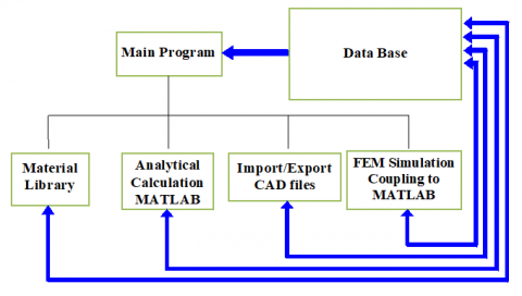
In this Section, a program that has been developed to combine analytical calculations in MATLAB programming with simulation in a finite element method (FEM) environment as shown in Figure 1. This program is divided into three main parts: analytical calculation, exporting drawings, and magnetic FEM stimulation. The analytical calculation has been stored and integrated into the MATLAB programming. After completing the calculations, the detailed rotor and stator laminations to their respective drawings are exported in a standard format. Next, the program auto-integrates 2D stator and rotor designs into the FEM simulation environment, which allows to compute the output torque, power and air gap flux density by using integral functions. The results of the simulation are then stored in a database which can be used for further comparison. Finally, a material library is associated with the FEM library to do a post processing.
Figure 1. Analytical program structure
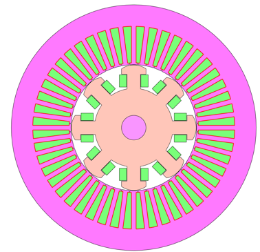
In this study, the practical motor is herein a proposal IPM of 150kW, with 8 poles and 48 slots, where the PM arranged in the delta shape. The stator core and rotor lamination are presented in Figure 2.
Figure 2. Stator core and rotor Lamination of IPM 150kW
The main parameters of the proposed such as the number of slot and poles, stack length, the diameter of the stator and rotor, and the air-gap length are already given in Table 1. The power inverter for this machine is designed with 396VDC/450 A. The continuous rated power is 80 kW and peak power is 150kW, and the maximum speed of the machines is 20000 rpm. The performance specifications typically include requirements for power, torque, efficiency, speed, and other characteristics. In order to obtain the performance of this machine, the size and shape of the machine must be carefully chosen. The size of the machine is determined by the maximum physical size, which may be limited by factors such as available space, weight and cost. The temperature rise of the machine is also an important consideration, as excessive temperature rise can reduce the lifespan and efficiency of the machine. The calculation process of the IPM motor is performed in Figure 3.
Figure 3. The calculation process of the IPM motor
Table 1. Main parameters
|
Parameter |
Value |
|
Volkswagen ID.3 |
2020 |
|
Peak power kW |
150 |
|
Winding Type |
Hairpin |
|
Stator assy weight |
23.6 |
|
Stator LAM weight |
17.98 |
|
Copper weight |
5.388 |
|
kW/ Stator Assembly |
6.36 |
|
kW/kg Copper |
27.40 |
|
kW/ kg Stator Iron |
8.30 |
|
Cooling system |
Liquid cooling |
|
Voltage |
394 |
|
48 slots, 8 poles |
|
|
Shaft diameter |
60mm |
|
Rotor outer diameter |
161 mm |
|
Stator inner diameter |
162.4 mm |
|
Airgap length |
0.7 mm |
|
Stator stack length |
140 mm |
|
Rotor stack length |
141.6 mm |
|
Average stack |
141.6 mm |
In this process, selection of materials and geometries for different components of the machine, including the stator, rotor, and laminations, is essential. The choice of materials and geometries directly influences the flux and current densities within the machine, subsequently impacting the power loss density and cooling requirements. The power loss density plays a critical role in establishing the cooling requirements of the machine. It represents the power dissipated per unit volume within the machine and is closely linked to the flux and current densities. To ensure a manageable temperature rise, it is crucial to design an efficient cooling system capable of effectively removing this generated heat. However, the same principles of balancing performance specifications and constraints still apply. By carefully choosing the materials and geometries of the various components, it is possible to achieve the desired performance while staying within the limits of material properties and temperature rise.
Figure 4. Model of IPM motor with VV shape (left) and delta shape (right)
Figure 5. Model of EESM motor
A comparison between two types of electric motors (IPM motor and EESM) is respectively shown in Figures 4 and 5, where Figure 4 is pointed the model of IPM with the double V (VV) and delta shapes. The FEM will be introduced to evaluate the design characteristics of the two these motors, with particular attention given to the flux density.
In order to satisfy the performance specifications given in Table 1 and Figure 2 for the electric vehicle (EV), the motors used in the design must exhibit exceptional capabilities in flux-weakening and peak torque output while operating within the limits of current and voltage imposed by the inverter. Consequently, the primary restriction involves the maximum current and voltage for the IPM motor and EESM, which can be derived from reference [12, 13].
Basic parameters are defined by an analytical model. Indeed, if the rotor diameter (D) is equal to rotor length (L), the electromagnetic torque (T) of the IPM motor can be defined [12, 13]:
$T=\frac{\pi}{4} . D^2 . L_s . T R V$ (1)
where, the torque volume density (TVR) is then defiened as:
$T R V=\frac{\pi}{\sqrt{2}} k_{W 1} A . B \mathrm{Nm} / \mathrm{m}^3$ (2)
At a synchronous speed, the electromagnetic torque and power can be computed via the phasor diagram as pointed out in Figure 6.
Figure 6. Phasor diagram of IPM motor
The phasor diagram is divided into two parts: the electrical quantities on the left side and the corresponding magnetic flux linkages on the right side. The magnetic flux linkages are represented by space vectors, which are three-dimensional vectors that rotate in space at an angular velocity. These vectors are used to describe the physical orientation of the magnetic flux in the motor. The space vectors can also be projected onto a 2-D to create a phasor diagram that represents the magnitude and phase angle of the magnetic flux linkages. In general, the phasor diagram is a useful tool for analyzing the performance of electric machines, including IPM and EESM motors. It allows designers and engineers to visualize the relationship between electrical and magnetic quantities, and to make informed decisions about the design and operation of the motor.
Based on the diagram in Figure 6, the armature current ( $I_{\text {arm }}$ ) is defined via the d- and q- axis component currents (Id and Iq) [12, 13]:
$I_{\text {arm }}=\sqrt{I_d^2+I_q^2} \leq I_{\text {arm_max }}$ (3)
where, Iarm_max is the maximum current given by the inverter. The maximum phase (Varm_max) is thus defined as:
$V_{\text {arm_max }}=p \sqrt{\left(L_d I_d+\lambda_m\right)^2+\left(L_q I_q\right)^2} \leq \frac{V_{D C}}{\sqrt{3} w_r}$ (4)
where, p is the number of pole pair, Ld is the d-axis inductance, Lq is the q-axis ductance, VDC is the battery voltage and wr is the speed of rotor. At the maximum speed (wr_max), the back electromagnetic force (EMF) (E) is defined as:
$E=p \lambda_m w_{r_{-} \max } \leq \frac{V_{D C}}{\sqrt{3}}$ (5)
In order to obtain a maximum flux weakening capability and constant power speed range, it is required by the traction motor. For the IPM motor, the condition need to be satisfied [12]:
$\lambda_m=L_d I_{\text {arm }}$ (6)
and for the EESM motor [13]:
$\lambda_m=L_q I_{\text {arm }}$ (7)
It should be noted that the conditions in (8) and (9) are the ideal conditions. The linkage flux in stator is actually limited, thus the PM will not be demagnetized.
In order to obtain the high efficiency for a wide speed range, the maximum torque per ampere control at the low speed is maintained for the peak torque and the flux weakening control at the high speed. For the two types of motors, the electromgantic torque are then expressed as [14-16]:
$\begin{aligned} & T=\frac{3}{2} p\left[\lambda_d\left(I_d, I_q\right) I_q-\lambda_q\left(I_d, I_q\right) I_d\right] =\frac{3}{2} p[\lambda_d\left(I_d=0, I_q\right) I_q +\frac{\lambda_d\left(I_d, I_q\right)-\lambda_d\left(I_d=0, I_q\right)}{I_d} I_d I_q -\frac{\lambda_q\left(I_d, I_q\right)}{I_q} I_d I_q] =\frac{3}{2} p\left\{\lambda_m\left(I_q\right) I_q\right. \left.+\left[L_d\left(I_d, I_q\right)-L_q\left(I_d, I_q\right)\right] I_d I_q\right\} \\ & \end{aligned}$ (8)
where, λd and λq are d- and q-axis flux linkage, respectively. The flux linkages of PM are then expressed by [17, 18]:
$\lambda_m\left(I_q\right)=\lambda_d\left(I_d=0, I_q\right)$ (9)
$\lambda_d\left(I_d, I_q\right)=L_d\left(I_d, I_q\right) I_d+\lambda_m\left(I_q\right)$ (10)
$\lambda_q\left(I_d, I_q\right)=L_q\left(I_d, I_q\right) I_q$ (11)
It should be noted that from Eqs. (3)-(11), the value of pλm in Eqs. (10) and (11) is small for a low back EMF at a high speed. On the other hand, it is large for the high torque and a high efficiency.
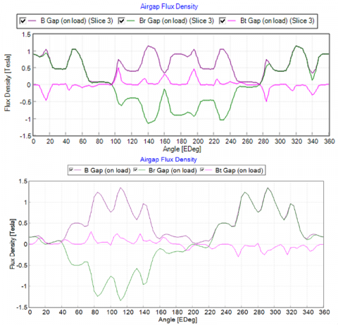
In order to validate the theory developed in Section 3, in this section, the results of two types of IPM motor and EESM are analysed by the FEM. The flux density distribution in the air gap of the IPM motor and EESM is presented in Figure 7. It can be seen that due to the flux-concentration effect of its excited coil configuration, the EESM has a higher air-gap flux density than that of the IPM motor, despite having a lower magnet strength.
The comparison of average torques between the IPM motor with different type of rotor shapes (VV and Delta) and EESM motors is pointed out in Figure 8. It shows that the average torque of the EESM with a field coil current of 5A is higher than the that of the IPM motor with VV and Delta shapes. The cogging torque distribution of the EESM is indicated in Figure 9. It is found that the peak value of the cogging torque decreases with an increase in the step skewing rotor, as well as with a skewing stator or rotor.
Figure 7. Flux density distribution in the air gap of the IPM motor (top) and EESM (bottom)
Figure 8. Comparison of average torques between the IPM motor with different type of rotor shapes (VV and Delta) and EESM motors
Figure 9. Cogging torque distribution of the EESM
Additionally, the cogging torque is a phenomenon that causes a periodic variation in the torque output of motor due to the interaction of the rotor magnets with the stator teeth. This variation can lead to vibration and noise, which can be undesirable in some applications. Overall, it seems that the EESM has some advantages over the IPM motor in terms of torque performance and cogging torque reduction.
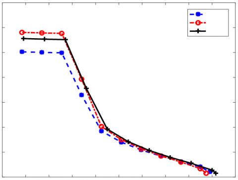
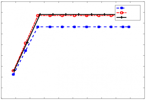
Figures 10, 11 and 12 provide a comparative analysis of the output power, power loss and efficiency maps between the IPM motor and EESM. In Figure 10, at the speed of 20000 rpm, the output power is equal to 160 N.m for the EESM and 157 N.m for the IPM motor with delta shape. In Figure 11, at the speed of 6000 rpm, the power loss of EESM is lower than that of the IPM motor.
Figure 10. Comparison of output powers for two types of motors (IPM motor and EESM)
Figure 11. Comparison of power loss for two types of motors (IPM motor and EESM)
Figure 12. Comparison of efficiency for two types of motors (IPM motor and EESM)
In Figure 12, it shows that there is a difference in efficiency between the EESM and IPM motor. It can be seen that in the higher-speed region, the efficiency curve of the EESM is improved in comparison with the IPM motor (VV and delta shapes). This suggests that the EESM may be more suitable for high-speed applications where efficiency is a critical factor. Figure 13 indicates the efficiency maps of two types of motors, where the efficiency map of IPM motor is on the top and on the bottom for the EESM. It is shown that the maximum efficiency map of torque and speed of the EESM is larger than that of the IPM.
Figure 13. The efficiency map of IPM motor (top) and EESM (bottom)
Table 2. Comparison of electromagnetic parameters between IPM motor and EESM
|
Parameters |
IPM |
EESM |
Unit |
|
Maximum torque possible |
192.19 |
232.31 |
Nm |
|
Average torque |
167.49 |
233.46 |
Nm |
|
Torque ripple |
3.3047 |
33.715 |
Nm |
|
Torque ripple [%] |
1.9608 |
14.365 |
% |
|
Cogging torque ripple (Vw) |
0.63751 |
16.405 |
Nm |
|
Speed limit for constant torque |
6558.7 |
5152.4 |
rpm |
|
No load speed |
8661.5 |
4921.7 |
rpm |
|
Electromagnetic Power |
1.15E+05 |
98310 |
Watts |
|
Input power |
1.16E+05 |
1.02E+05 |
Watts |
|
Total losses (on load) |
2138.6 |
4652.4 |
Watts |
|
Output power |
1.14E+05 |
97673 |
Watts |
|
System efficiency |
98.158 |
95.453 |
% |
|
Shaft torque |
167.42 |
233.18 |
Nm |
The comparison of electromagnetic parameters between IPM motor and EESM is given in Table 2. It founds that the EESM has a maximum efficiency of 95.5%, with a maximum torque of 232 N.m, at a speed of 5152 rpm, whereas the IPM motor has a maximum torque of 192.2 N.m, at a speed of 6558 rpm. These results suggest that the EESM machine has some advantages over the IPM in terms of maximum torque and average torque at high speeds.
The analysis and comparison of flux density torque, power and efficiency of the EESM and IPM motor for EV applications have been successfully obtained. The obtained results have shown that the EESM has some advantages over the IPM motor in terms of efficiency and output power, particularly in the lower-torque and higher-speed regions. This information could be valuable for researchers and engineers working in the field of electric vehicle motor design and development. Also, the development of the proposed method suggests that the EESM can be a promising solution for improving the performance of electromagnetic parameters in various applications.
This research is funded by Hanoi University of Science and Technology.
[1] Peng, C., Wang, D., Feng, Z., Wang, B. (2021). A new segmented rotor to mitigate torque ripple and electromagnetic vibration of interior permanent magnet machine. IEEE Transactions on Industrial Electronics, 69(2): 1367-1377. https://doi.org/10.1109/TIE.2021.3063869
[2] Zhao, W., Lipo, T.A., Kwon, B.I. (2015). Torque pulsation minimization in spoke-type interior permanent magnet motors with skewing and sinusoidal permanent magnet configurations. IEEE Transactions on Magnetics, 51(11): 1-4. https://doi.org/10.1109/TMAG.2015.2442977
[3] Yıldırız, E., Güleç, M., Aydın, M. (2018). An innovative dual-rotor axial-gap flux-switching permanent-magnet machine topology with hybrid excitation. IEEE Transactions on Magnetics, 54(11): 1-5. https://doi.org/10.1109/TMAG.2018.2848878
[4] Li, W., Ching, T.W., Chau, K.T. (2017). Design and analysis of a new parallel-hybrid-excited linear vernier machine for oceanic wave power generation. Applied Energy, 208: 878-888. https://doi.org/10.1016/j.apenergy.2017.09.061
[5] Liu, Y., Zhang, Z., Zhang, X. (2017). Design and optimization of hybrid excitation synchronous machines with magnetic shunting rotor for electric vehicle traction applications. IEEE Transactions on Industry Applications, 53(6): 5252-5261. https://doi.org/10.1109/TIA.2017.2720671
[6] Yang, Y., Castano, S.M., Yang, R., Kasprzak, M., Bilgin, B., Sathyan, A., ... & Emadi, A. (2016). Design and comparison of interior permanent magnet motor topologies for traction applications. IEEE Transactions on Transportation Electrification, 3(1): 86-97. https://doi.org/10.1109/TTE.2016.2614972
[7] Liu, X., Lin, Q., Fu, W. (2017). Optimal design of permanent magnet arrangement in synchronous motors. Energies, 10(11): 1700. https://doi.org/10.3390/en10111700
[8] Wang, A., Jia, Y., Soong, W. L. (2011). Comparison of five topologies for an interior permanent-magnet machine for a hybrid electric vehicle. IEEE Transactions on Magnetics, 47(10): 3606-3609. https://doi.org/10.1109/TMAG.2011.2157097
[9] Ding, T., Takorabet, N., Sargos, F.M., Wang, X. (2009). Design and analysis of different line-start PM synchronous motors for oil-pump applications. IEEE Transactions on Magnetics, 45(3): 1816-1819. https://doi.org/10.1109/TMAG.2009.2012772
[10] Khlaief, A., Boussak, M., Gossa, M. (2013). Model reference adaptive system based adaptive speed estimation for sensorless vector control with initial rotor position estimation for interior permanent magnet synchronous motor drive. Electric Power Components and Systems, 41(1): 47-74. https://doi.org/10.1080/15325008.2012.732657
[11] Manh, T.H., Minh, D.B., Minh, T.P., Quoc, V.D. (2023). Investigation of the influence of skewed slots and degmagnetization effects to line start permanent magnet assistance synchronous reluctance motors. Engineering, Technology & Applied Science Research, 13(1): 9807-9811. https://doi.org/10.48084/etasr.5307
[12] Huynh, T.A., Hsieh, M.F. (2018). Performance analysis of permanent magnet motors for electric vehicles (EV) traction considering driving cycles. Energies, 11(6): 1385. https://doi.org/10.3390/en11061385
[13] Wang, J., Yuan, X., Atallah, K. (2012). Design optimization of a surface-mounted permanent-magnet motor with concentrated windings for electric vehicle applications. IEEE Transactions on Vehicular Technology, 62(3): 1053-1064. https://doi.org/10.1109/TVT.2012.2227867
[14] Duc, H.B., Dinh, B.M., Bao, D.T., Tu, P.M., Vuong, D.Q. (2023). Improving performances of interior permanent magnet synchronous motors by using different rotor angles. Journal Européen des Systèmes Automatisés, 56(1): 115. https://doi.org/10.18280/jesa.560115
[15] Soong, W.L., Ertugrul, N. (2002). Field-weakening performance of interior permanent-magnet motors. IEEE Transactions on Industry Applications, 38(5): 1251-1258. https://doi.org/10.1109/TIA.2002.803013
[16] Guglielmi, P., Boazzo, B., Armando, E., Pellegrino, G., Vagati, A. (2012). Permanent-magnet minimization in PM-assisted synchronous reluctance motors for wide speed range. IEEE Transactions on Industry Applications, 49(1): 31-41. https://doi.org/10.1109/TIA.2012.2229372
[17] Liu, X., Chen, H., Zhao, J., Belahcen, A. (2016). Research on the performances and parameters of interior PMSM used for electric vehicles. IEEE Transactions on Industrial Electronics, 63(6): 3533-3545. https://doi.org/10.1109/TIE.2016.2524415
[18] Duc, H.B., Dinh, B.M., Vuong, D.Q. (2022). Analytical and FEM methods for line start permanent magnet synchronous motor of 2.2 kW. Journal Européen des Systèmes Automatisés, 55(6): 715. https://doi.org/10.18280/jesa.550603