Mohamed Fadi Kethiri*![]() | Omar Charrouf
| Omar Charrouf![]()
© 2023 IIETA. This article is published by IIETA and is licensed under the CC BY 4.0 license (http://creativecommons.org/licenses/by/4.0/).
OPEN ACCESS
Fault-tolerant control (FTC) is a design methodology that ensures control systems continue to function even with component faults or failures. FTC is particularly used in Brushless DC Motors (BLDC), electric motors that use electronic commutation instead of brushes. These motors use three Hall effect sensors, placed 120 degrees apart, to accurately determine the rotor's position and control its speed and torque. This paper presents a methodology using electronic logic gates to compensate for sensor faults by analyzing the behavior of the Hall effect signals, translating them into binary language, and enabling continued control of the BLDC motor. This methodology improves the fault-tolerant capability of BLDC motors and ensures their continued functioning despite component failures. Simulation and validation results using Matlab/Simulink demonstrate the effectiveness of the proposed methodology in ensuring the continued operation of the BLDC motor despite component failures. The proposed fault-tolerant control strategy can enhance the reliability and performance of BLDC motors, making it a valuable tool for various industrial applications.
BLDC, fault tolerant control, hall effect sensor, speed control, electronic logic gates, Matlab/Simulink
Electric motors have revolutionized the world by enabling the creation of machines and appliances that have made work easier and more efficient. Brushless DC (BLDC) motor, has gained popularity due to its high efficiency, low maintenance, and ability to operate at higher speeds. However, like any other motor, BLDC motors are prone to faults that can impact their performance and lead to failures. Consequently, FTC systems have been developed to detect and mitigate these faults, ensuring the continued operation of the motor, even in the presence of faults.
The primary focus of this study is to investigate FTC techniques for BLDC specifically in the event of Hall effect sensor failure, which poses a significant challenge in BLDC motor applications, and addressing this issue is crucial to enhance the overall performance, reliability, and safety of systems using these motors. This study aims to make a valuable contribution to the field of FTC for BLDC motors by using electronic logic gates to replicate the signals of a healthy Hall effect sensor. By employing this innovative approach, the study aims to provide a comprehensive understanding of the FTC technique, its effectiveness, and its potential implications for practical applications.
To achieve this objective, this paper is organized as follows: Section 2 reviews the relevant literature related to FTC on BLDC and AC motors. The operating principles of BLDC motors and designing sliding mode for speed control are discussed in Section 3. The proposed FTC technique is presented in Section 4. Section 5 presents the simulation findings, and a discussion of the outcomes is provided. Finally, Section 6 summarizes the study's findings and their implications for future research in FTC for BLDC motors.
Theme 1: Importance of FTC in Ensuring Safety and Reliability:
According to Odgaard et al. [1], FTC is crucial for ensuring the safety, reliability, and availability of complex systems like aircraft, power plants, and chemical processes. Faults can occur due to various reasons, and the consequences can range from minor performance degradation to catastrophic failures. FTC techniques aim to mitigate the impact of faults in real-time, preventing system downtime, reducing maintenance costs, and improving overall system performance.
Theme 2: FTC Application to BLDC Motors:
The book by Noura et al. [2] in (2009) provides an extensive review of FTC and its application to BLDC motors. The authors emphasize the ability of FTC to maintain system functionality even in the presence of component or sensor failures, which is crucial in applications with severe consequences such as aerospace, automotive, and medical equipment. They also highlight the importance of selecting appropriate FTC methods based on specific application and system requirements.
Theme 3: Novel FTC Schemes for BLDC Motors:
According to Heo et al. [3], a novel FTC scheme for BLDC motors is proposed, utilizing a sliding mode observer and a hybrid controller to estimate fault magnitude and compensate for disturbances. The simulation results demonstrate the effectiveness of the proposed scheme in suppressing fault effects and maintaining desired motor speed. Similarly, Tashakori and Ektesabi [4] proposes an FTC strategy based on sliding mode control for BLDC motor drives, including a fault detection and diagnosis module. Simulation results validate the strategy's ability to detect and compensate for faults effectively.
Theme 4: Effectiveness of FTC in BLDC Systems:
A study conducted by Zhang and Feng [5] analyses the effectiveness of FTC in BLDC systems. The study shows that FTC can effectively regulate speed and torque under different operating conditions. The performance of FTC can be further improved by employing advanced control techniques like model predictive control and adaptive control.
Theme 5: Overview and Evaluation of FTCSs:
In their work Amin and Hasan [6] provides a thorough analysis and evaluation of state-of-the-art FTCSs, discussing different design approaches and fault detection and diagnosis techniques. The authors highlight the importance of FTCSs in modern industrial systems and emphasize the need for further research in more efficient and reliable fault detection and diagnosis techniques.
Theme 6: Examples of FTC Implementation in BLDC Motors:
In the study by Aqil and Hur [7] the authors present three examples of FTC implementation in BLDC motors, utilizing sensor less, sensor-based, and hybrid approaches. All three approaches effectively detect and mitigate faults in BLDC motors, improving their reliability and performance.
Theme 7: Fault Detection Techniques for BLDC Motors:
As stated by Vanchinathan et al. [8] discusses various fault detection techniques for BLDC motors, including vibration analysis, motor current signature analysis, and temperature monitoring. These techniques have shown effectiveness in detecting faults and preventing costly equipment failures.
Theme 8: Challenges and Limitations of FTC for BLDC Motors:
The literature review conducted by Dilmi et al. [9] explores the challenges and limitations of fault-tolerant control for BLDC motors, such as the need for accurate fault detection and the trade-off between system performance and safety. The review calls for further research in this area to address these challenges.
Theme 9: Latest Research in FTC on BLDC Motors:
Mohanraj et al. [10] extensively review the latest research in FTC on BLDC motors, discussing various approaches, fault detection and diagnosis methods, and implementation strategies. The study emphasizes the significance of FTC in maintaining reliability and safety in industrial and automotive applications.
The existing body of the literature reveals several gaps that require further exploration:
· Insufficient research has been conducted on specific FTC techniques tailored specifically to the needs and characteristics of BLDC motors.
· There is a lack of comprehensive comparative studies that evaluate and compare the performance of various FTC methods specifically in the context of BLDC motors.
· Limited attention has been given to the practical implementation challenges and real-world constraints associated with integrating FTC into industrial environments, thereby requiring additional research in this area.
· There is a dearth of research focusing on the development and evaluation of more efficient and reliable fault detection and diagnosis techniques that are specifically designed for BLDC motors.
· The impact of FTC techniques on overall system performance, energy efficiency, and operating costs in the context of BLDC motors has not been extensively studied.
· There is limited research available regarding FTC in emerging applications of BLDC motors, such as renewable energy systems, robotics, and electric vehicles, necessitating further investigation to address the specific challenges, requirements, and potential benefits associated with these applications.
3.1 The operating principles of BLDC motors
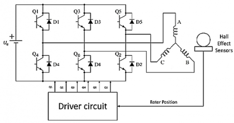
Current commutation is done by a six-step inverter as shown in a simplified form in Figure 1.
Figure 1. Simplified BLDC drive scheme [11]
The BLDC motor with three phases is operated in a manner where two phases are energized while the third phase is off, depending on the rotor's position. The two phases that produce the most torque are selected. Figure 2 displays how the position sensors generate a three-digit number (H1, H2, H3) that changes every 60° (electrical degrees) [11, 12].
Figure 2. Back-emf's, phase currents and position sensor signals [13]
3.2 Sliding mode for speed control
Sliding mode exponential (SME) is an adaptive control method that uses a combination of sliding mode control and exponential control. It is an optimal, robust and reliable control technique that can be applied in a wide range of applications. The design of SME involves the tuning of the gains associated with both the sliding mode and the exponential terms to obtain the desired performance. The sliding mode term guarantees robustness of the system while the exponential term acts as a feed-forward signal to improve the transient response and steady-state accuracy [14]. It is crucial to select the correct weighting factor between these two terms to obtain optimal results. SME also requires a proper selection of the switching surface (or boundary) to ensure that it is insensitive to external disturbances. Thus, SME is an effective and efficient control technique for a variety of applications [15].
(a) SME design
The sliding surface S2 is defined with the motor speed tracking error:
$S_2=\omega_{r e f}-\omega_m$ (1)
Exponential approach law:
$\dot{S}=-\varepsilon \operatorname{sign}\left(S_2\right)-\gamma S_2$ (2)
(b) Stability proof
In order to determine the stability of the controlled system, Lyapunov function was selected:
$V(x)=\frac{S_2^2}{2}$ (3)
The derivative of it can be obtained:
$\dot{V}(S)=S_2 \dot{S}=-\alpha_1 S^3\left|S_2\right|$ sign $-\alpha_2 S_2^2$ (4)
Therefore, $\dot{V}\left(S_2\right)$ is less than or equal to 0 for s in any range, which satisfies the stability condition of Lyapunov, and the system is stable. Overall, the SME design for the BLDC motor application combines the robustness of sliding mode control with the improved transient response and steady-state accuracy of exponential control. By properly tuning the gains and selecting the switching surface, the SME controller achieves optimal performance and enhances the fault-tolerant control technique for the BLDC motor. It provides stability guarantees and effective control in the presence of disturbances, making it suitable for a variety of applications.
The fault detection system plays a crucial role in the proposed FTC technique by continuously monitoring the system for any faults or anomalies. It analyzes the signals from the Hc sensor to detect any deviations from expected behavior, such as abnormal currents or Hall-effect patterns. When a fault is detected, the fault detection system triggers appropriate actions to mitigate the impact of the fault and ensure the system's continued operation. The advantages and improvements offered by this fault detection system within the proposed FTC technique can be summarized as follows:
·Early Fault Detection: The fault detection system provides early detection of faults or anomalies in the system. By continuously monitoring the signals from the Hc sensor, it can quickly identify deviations from normal behavior, allowing for timely intervention before the fault escalates or affects the system's performance.
·Enhanced Reliability: The fault detection system enhances the overall reliability of the control technique by promptly detecting faults. By detecting faults early on, it enables the implementation of fault-tolerant control strategies to mitigate the effects of the fault and maintain system operation within acceptable bounds.
·Increased Safety: The fault detection system contributes to increase safety by identifying faults that may pose risks to the system or its surroundings. It enables proactive measures to be taken, such as activating backup components or adjusting control parameters, to ensure safe and reliable system operation.
·Improved System Performance: By quickly detecting faults and implementing appropriate FTC strategies, the proposed technique can maintain system performance even in the presence of faults. This leads to improved system availability, reduced downtime, and enhanced operational efficiency.
Compared to existing fault detection and control methods [1-10], the proposed FTC technique offers a more comprehensive and integrated approach. It offers quicker reaction times, more precise problem localisation, and more effective fault mitigation by directly integrating the fault detection system with the control strategy. This integration results in a more robust and dependable system, making it ideal for critical applications where fault tolerance and system safety are crucial. The most important phase is the conversion of current and Hall-effect signals into binary logic. A positive or negative current is represented as a signal of 1 in this operation. A zero current, on the other hand, is indicated by a signal of 0. The results of this conversion can be easily extracted from Figure 2 and are presented in a clear and concise manner in Table 1. Through this process, we gain a deeper understanding of the fault detection system and the critical role that the Hc sensor plays in ensuring its success.
Table 1. Hall effect sensor signals and stator currents in 360 degrees
|
Ha |
1 |
1 |
0 |
0 |
0 |
1 |
|
Hb |
0 |
1 |
1 |
1 |
0 |
0 |
|
ia |
1 |
1 |
0 |
1 |
1 |
0 |
|
ib |
1 |
0 |
1 |
1 |
0 |
1 |
|
ic |
0 |
1 |
1 |
0 |
1 |
1 |
|
Hc |
0 |
0 |
0 |
1 |
1 |
1 |
It is imperative that we reach the output signals indicated in Red, as they represent the ultimate goal. These signals are constantly changing every 60°, making it all the more important that we have a clear understanding of their significance. In order to ensure that we are able to successfully achieve these outputs, it is crucial that we follow the wiring diagram provided in Figure 3 with utmost precision.
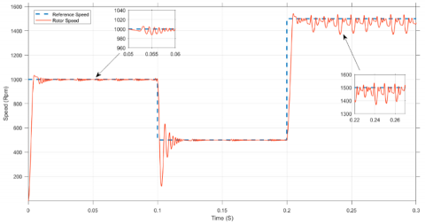
Figure 4 depicts the current ripples over simulation time for three different speed regions, each at zero torque load (Tl=0 Nm), using the motor parameters detailed in Table 2. The speed profile is set to 1000 Rpm from 0 to 0.1 s, followed by a decrease to 500 Rpm from 0.1 to 0.2 s, and finally an increase to 1500 Rpm from 0.2 s onwards. This speed profile is chosen to simulate a broad range of cases operating in a real application. The simulation is conducted in Matlab Simulink, and the rotor speed for normal functioning and the proposed method for failure Hc sensor are presented in Figures 5 and 6, respectively.
Figure 4. Stator currents for different speed regions
Figure 5. Rotor speed for healthy functioning
Figure 6. Rotor speed with the proposed FTC
The simulation is conducted to analyse the dynamic tracking for speed due to SMC presented in Figure 5 as a healthy functioning. The speed was set to 1000 RPM from 0 to 0.1 seconds, 500 RPM from 0.1 to 0.2 seconds, and 1500 RPM from 0.2 seconds onwards. The results of the simulation were presented in Figure 6. According to the proposed scheme, the traction of the speed was ensured in the first and second regions (medium and low speed). However, there was a chattering observed in the simulation, which became more significant when the system moved to the third region (high speed). This undesirable chattering is caused by the high current ripples, as shown in Figure 4. To elaborate further, this chattering occurs due to the undesired rapid switching of control actions, which is an inconvenience associated with using logic gates. It is important to note that, as of the time of writing this paper, no solution has been found to address this chattering issue. However, the simulation results provide valuable insights into the system's performance under different speed regions and can help improve the system's overall efficiency.
Table 2. Motor and control parameters
|
Parameter |
Value |
Unit |
|
Stator winding resistance Rs |
2.8750 |
Ω |
|
Stator phase inductance Ls |
8.5e-3 |
H |
|
The number of pole pairs p |
4 |
- |
|
Moment of inertia J |
0.0027 |
Kg.m2 |
|
Damping coefficient B |
0.0004924 |
- |
|
DC-bus voltage Vdc |
300 |
V |
|
Sampling time Ts |
1e-6 |
S |
In this study, we conducted a number of simulations to analyse the dynamic tracking of a BLDC’s speed using SMC and a proposed FTC scheme for obtaining Hc signals. Results showed that the proposed FTC scheme demonstrate promising results in ensuring satisfactory traction of speed in the medium and low-speed regions. However, a chattering was observed when the system moved to the high-speed region, which could be attributed to high current ripples. Our paper offers a practical solution for obtaining the Hall effect signals in the industrial field. Its ease of installation and equipment make it a viable option for various applications, including potential use in electric vehicles. While there may be other methods available, our proposal offers a competitive advantage in terms of affordability and ease of use.
Limitations and Future Research Directions:
· One limitation mentioned earlier is the issue of chattering. This chattering issue refers to the unwanted rapid switching of control actions and the electronic logic gates, which can affect the stability and performance of the proposed method. To address this limitation and other potential challenges, future research could focus on the following directions:
· Chattering mitigation techniques: Develop and implement strategies to reduce or eliminate chattering in the proposed FTC technique. This could involve the use of smoothing filters, adaptive algorithms, or optimization methods to achieve more stable control actions.
· Performance optimization: Explore methods to optimize the performance of the proposed technique, such as enhancing the accuracy of fault detection and diagnosis algorithms or improving the responsiveness of the control system to faults.
· Robustness analysis: Conduct a thorough robustness analysis to evaluate the proposed method's performance under different operating conditions, environmental factors, and potential disturbances. This analysis would help identify any limitations or vulnerabilities that need to be addressed for real-world applications.
· Validation in practical scenarios: Perform extensive testing and validation of the proposed method in real-world industrial settings. This would provide empirical evidence of its effectiveness, identify any additional limitations or challenges, and validate its practicality and performance compared to existing methods.
The proposed method can be refined, optimized, and validated by addressing these limitations and conducting further research in these areas, leading to its successful implementation and broader adoption in industrial applications.
|
ωref |
speed reference (rad/s) |
|
ωm |
measured speed (rad/s) |
|
ε |
positive real constant |
|
γ |
positive real constant |
|
α1 |
positive real constant |
|
α2 |
positive real constant |
|
sign(S) |
sign function of sliding surface |
[1] Odgaard, P.F., Stoustrup, J., Kinnaert, M. (2009). Fault tolerant control of wind turbines - A benchmark model. IFAC Proceedings Volumes, 42(8): 155-160. https://doi.org/10.3182/20090630-4-ES-2003.00026
[2] Noura, H., Theilliol, D., Ponsart, J.C., Chamseddine, A. (2009). Fault-tolerant control systems: Design and practical applications. London, U.K.: Springer.
[3] Heo, H.J., Im, W.S., Kim, J.M., Kim, Y.G., Oh, J.S. (2012). Fault tolerant control methods of dual type independent multi-phase BLDC motor under open-switch fault conditions. In 2012 Twenty-Seventh Annual IEEE Applied Power Electronics Conference and Exposition (APEC), pp. 1591-1596. https://doi.org/10.1109/APEC.2012.6166032
[4] Tashakori, A., Ektesabi, M. (2013). A simple fault tolerant control system for Hall Effect sensors failure of BLDC motor. In 2013 IEEE 8th Conference on Industrial Electronics and Applications (ICIEA), pp. 1011-1016. https://doi.org/10.1109/ICIEA.2013.6566515
[5] Zhang, Q., Feng, M. (2019). Fast fault diagnosis method for Hall sensors in brushless DC motor drives. IEEE Transactions on Power Electronics, 34(3): 2585 2596. https://doi.org/10.1109/TPEL.2018.2844956
[6] Amin, A.A., Hasan, K.M. (2019). A review of fault tolerant control systems: Advancements and applications. Measurement, 143: 58-68. https://doi.org/10.1016/j.measurement.2019.04.083
[7] Aqil, M., Hur, J. (2021). Multiple sensor fault detection algorithm for fault tolerant control of BLDC motor. Electronics, 10(9): 1038. https://doi.org/10.3390/electronics10091038
[8] Vanchinathan, K., Valluvan, K.R., Gnanavel, C., Gokul, C., Albert, J.R. (2021). An improved incipient whale optimization algorithm based robust fault detection and diagnosis for sensorless brushless DC motor drive under external disturbances. International Transactions on Electrical Energy Systems, 31(12): e13251. https://doi.org/10.1002/2050-7038.13251
[9] Dilmi, I., Bouguerra, A., Djrioui, A., Chrifi-Alaoui, L. (2021). Interval Type-2 fuzzy logic-second order sliding mode based fault detection and active fault-tolerant control of brushless DC motor. Journal Européen des Systèmes Automatisés, 54: 475-485. https://dx.doi.org/10.18280/jesa.540311
[10] Mohanraj, D., Aruldavid, R., Verma, R., Sathyasekar, K., Barnawi, A.B., Chokkalingam, B., Mihet-Popa, L. (2022). A review of BLDC Motor: State of Art, advanced control techniques, and applications. IEEE Access, 10: 3235332373. https://doi.org/10.1109/ACCESS.2022.3175011
[11] Kumar, S.D. (2014). Modeling of brushless dc drive using genetic algorithm based tuning of pid controller. International Journal of Electrical, Electronics and Energy Research (IJEEER), 4(4): 113-126.
[12] Shamseldin, M. (2016). Speed control of high-performance brushless DC motor (Doctoral dissertation). Helwan University, Egypt. http://dx.doi.org/10.13140/RG.2.1.1472.9202
[13] Xia, C.L. (2012). Permanent Magnet Brushless Dc Motor Drives and Controls. John Wiley & Sons.
[14] Fallaha, C.J., Saad, M., Kanaan, H.Y., Al-Haddad, K. (2010). Sliding-mode robot control with exponential reaching law. IEEE Transactions on Industrial Electronics, 58(2): 600-610. https://doi.org/10.1109/TIE.2010.2045995
[15] Ma, H., Wu, J., Xiong, Z. (2017). A novel exponential reaching law of discrete-time sliding-mode control. IEEE Transactions on Industrial Electronics, 64(5): 3840-3850. https://doi.org/10.1109/TIE.2017.2652390