Husniyah Jasim Abdullah![]() | Parween R. Kareem
| Parween R. Kareem![]() | Sameer Algburi*
| Sameer Algburi*![]() | Ahmed Burhan Mohammed
| Ahmed Burhan Mohammed![]()
© 2023 IIETA. This article is published by IIETA and is licensed under the CC BY 4.0 license (http://creativecommons.org/licenses/by/4.0/).
OPEN ACCESS
In this investigation, the most popular multilevel inverter topologies and control approaches have been analyzed. The various benefits, such as low power dissipation on power switches, low harmonic contents, and low Electromagnetic Interference (EMI) outputs, Multilevel Inverter Topologies (MLIs) are finding more and more usage in medium and high-power applications. An optimization tool for the layout of a three-phase Voltage Source Inverter (VSI) using a diode-based rectifier has been created. For general-purpose industrial motor drives that use three-phase Alternating Current (AC), the Pulse Width Modulation (PWM) voltage source inverter with diode front-end rectifier has emerged as the converter of choice. This study discusses the implementation of predictive current control in a voltage source inverter. This technique makes use of a discrete-time model of the system to foresee the load current for every conceivable inverter-generated voltage vector. The voltage vector is chosen that minimizes a quality function. In this study, we use a quality function that measures the current error at the next sample interval. It is compared to hysteresis control and pulse width modulation control to see how well the suggested predictive control approach performs. The results demonstrate that the predictive strategy manages load current extremely well and outperforms traditional methods.
voltage source inverter, current control, dc link capacitor, low electromagnetic interference, control approach performs, low harmonic contents, AC electrical power, DC source
Inverters handle the conversion of DC to ac electricity. The AC output voltage has a potent fundamental component with adjustable frequency and amplitude, an inverter receives power from a DC source [1]. Voltage-Source Inverters (VSIs) and Current-Source Inverters (CSIs) can be separated based on the kind of the source [2]. The commonest power electronic converters are VSIs, which are second only to rectifiers [3].
A controlled or uncontrolled rectifier can provide a DC-input voltage for a VSI, as well as other DC sources like a battery or photovoltaic array. If a rectifier is utilized, as shown in Figure 1, LC-DC link is used to fed the inverter, much like how choppers use them. Due to the fact that the voltage across the link capacitor cannot change instantly, it might be considered a voltage source [4]. Additionally, it serves as a container for the electric charges that are transported to and from the inverter bridge through the irregular negative input currents [5].
Figure 1. Voltage source inverter provided by a diode rectifier
The supplying rectifier and power system can be separated from the high-frequency component of the inverter input current, by the inductor which is its main purpose [6]. The link inductor is not fundamentally required, Unlike the capacitor. In fact, to save space and money, the inductor is sometimes removed from practical inverters. Any number of output phases can be used to construct inverters [7]. The most popular inverters in use today are single phase and three phase inverters [8]. To boost dependability for some crucial applications, it has lately been suggested to build AC motors with more than three phases. Such motors require the same number of phases in their inverters in order to operate.
The paper [9] work presents an inclusive analysis of the OSG approach depending on most recent reference. This structure is used to study the DQ axis separation control, which is normally ignored in single-phase systems but is frequently explored for three-phase systems. We implement and analyze two separation techniques: quasi-compound proportional integral control and feed-forward control of reference current. The proposed theories and control measures were put to the test using the experimental findings.
In the study [10], the integrated (IMPPC) method proposed as a means of reducing steady-state errors in the current control system and enhancing performance of closed-loop. Additionally, compared to the conventional MPCC, Changes in the system's parameters have less of an impact on upgraded IMPCC. The successful development and use of the traditional MPCC and the enhancement of the IMPCC were shown through simulations and experimental findings. According to the experimental findings, the enhanced IMPCC offers the advantages of quick dynamic performance, no steady-state faults, and insensitivity to changes in system parameters.
The paper [11] suggested a new synchronous reference frame (DQ) current controller, for a three-phase grid-connected inverter with a Y/out transformer. The DQ derives a dynamic model of the inverter, filter, and transformer. There is also a description of the present controller's structure. The theoretical study was supported by experimental findings on a 20kW prototype, which also showed that the suggested current controller has high current control performance [11].
In our current study, DQ frame current control based current control of VSI inverter will be used.
The aim of the study is to develop and simulates a circuit with current control for a VSI inverter using a DQ-comparator.
To achieve this aim, the following objectives are accomplished:
1. Keeping the switching frequency fixed regardless of the current error derivative.
2. To provide harmonic performance that is as close as feasible to centered space vector open-loop modulation, a three-phase VSI must choose the three nearest space vectors during a single switching cycle.
3. In a three-phase system, compensating for interactions between phase legs without direct monitoring of the switching voltages in those legs.
Ramp comparison, hysteresis control, and predictive current control are the three primary methods used to regulate current in hard switched inverters. Predictive current control has the ability to provide the most accurate current control with the least amount of distortion and harmonic noise, but it is also the most complicated to install and is often matched to a particular load. In addition, there are additional issues in a real system due to mistakes induced by processing delays [12, 13]. For loads with both known and unknown back-EMF, this work proposes strategies for directly constructing a predictive current controller in a microprocessor. Because of their simplicity, these algorithms may be easily integrated into a working system, mitigating the effects of sampling delays and discretization mistakes [14]. The method given is confirmed by simulation. The majority of inverters used in industry, especially three-phase devices with medium and high power. when attaching single-phase inverter by a third leg, the power circuit of a three-phase VSI is created, shown in Figure 2.
Three switching variables, A, B, and C, will be given to the inverter if previously assumed, just one of the two power switches of each leg of the inverter is constantly run, disregarding the brief time intervals when both switches are off (dead time) [15, 16].
$\left(\begin{array}{l}V_{A B} \\ V_{B C} \\ V_{C A}\end{array}\right)=V_i\left(\begin{array}{ccc}0 & -1 & 0 \\ 0 & 1 & -1 \\ -1 & 0 & 1\end{array}\right)\left(\begin{array}{l}a \\ b \\ c\end{array}\right)$ (1)
There are eight states in an inverter, where all output terminals are clamped to the negative DC bus, state 0. And where they are clamped to the positive bus in state 7. Each state of an inverter is denoted by the letters ABC, forming eight states overall [17]. It is simple to demonstrate that VAB, VBC, and VCA are the instantaneous line-to-line output voltages.
Figure 2. A three-phase voltage source inverter power circuit
Hysteresis regulators is one of the primary classes of regulators. In addition to, linear PI regulators, and predictive dead-beat regulators. That have been created over the past few decades. A succinct overview of the three-phase systems' present control methods. one of the several PWM approaches, hysteresis band current control is often used Due to its clarity of use. Additionally, the rapid response current loop is the only load parameter that the method requires knowledge of. As a result of the need to manage peak-to-peak current ripple throughout the whole fundamental frequency wave. The PWM frequency swings within a band when using a current control with a fixed hysteresis band. In PWM technique with adaptive hysteresis-band current regulation, the band can be adjusted to the load to maximize performance.
The switching signals for Hysteresis current control are obtained by comparing the current error with a preset tolerance band. Based on a comparison between the actual phase current and the tolerance zone surrounding the reference current connected to that phase, this control is implemented [18].
On other hand, the phase current interactions that are frequent in three-phase systems have a negative impact on this form of band management. Since each phase current relies on its corresponding phase voltage as well as the voltage of the other two phases, this is mostly caused by interference between the commutations of the three phases. During the fundamental period, switching frequency may change depending on the load conditions, causing irregular inverter functioning.
Figure 3. Hysteresis current control schema
Figure 4. The hysteresis current control scheme in space vector
Figure 5. Diagram of a proportional and integral controller used to manage current in a three-phase voltage source converter
4.1 Hysteresis regulators
An inverters output currents (iA, iB, and iC) are measured and contrasted with the corresponding reference current waveforms (iA, iB, and iC). Current controllers provide switching variables, A, B, and C, for the inverter by applying current errors, ΔiA, ΔiB, and ΔiC. Figure 3 shows the space vector scheme [19].
Two current controllers can be used in place of three controllers, one controller for each phase of the inverter. the space vector Components (id and iq), and $\vec{i} *$ of output currents are calculated and compared with corresponding components, id and iq, of the reference current vector, $\vec{i} *$ based on the park transformation provided by (2) and applied to the output currents of>an inverter. Figure 4 for the d-component controller shows the three-level outputs of the present controllers, zd and zq. The Table 1 illustrates the Hysteresis current control switching in the below.
Table 1. DQ hysteresis current control switching
|
A |
B |
C |
zd |
zq |
|
1 |
1 |
0 |
1 |
1 |
|
1 |
0 |
0 |
1 |
0 |
|
1 |
0 |
1 |
1 |
‒1 |
|
1 |
1 |
0 |
0 |
1 |
|
0 |
0 |
0 |
0 |
0 |
|
1 |
0 |
1 |
0 |
‒1 |
|
0 |
1 |
0 |
‒1 |
1 |
|
0 |
1 |
1 |
‒1 |
0 |
|
0 |
0 |
1 |
‒1 |
‒1 |
For (zd, zq)=(0, 0), state 0 or state 7, “state 1 for (0, 1) and (1, 1), state 2 for (1, 1), state 3 for (1, 0), state 4 for (1, 0), state 5 for (1, 1), and state 6 for (1, 1) and (0, 1). These states produce the best control effects.
$\vec{\imath}=\left[\begin{array}{l}i_d \\ i_q\end{array}\right]=\left[\begin{array}{rrr}1 & -\frac{1}{2} & -\frac{1}{2} \\ 0 & \frac{\sqrt{3}}{2} & -\frac{\sqrt{3}}{2}\end{array}\right]\left[\begin{array}{l}i_A \\ i_B \\ i_C\end{array}\right]$ (2)
A switching table receives the signals zd and zq and applies them to a particular state of the inverter.
4.2 Linear proportional-integral regulators
Linear control is used by the PI regulator. The input of PI controller is the variation between the reference value and the feedback value. The output is the linear combination of the PI and the deviation. The PI controller is the most frequently used in power electronics due to its simplicity and dependability. The following is an expression for the transfer function of a traditional PI controller in the continuous domain:
$G_{p i}(s)=K_p+\frac{k_i}{s}$ (3)
where, the proportional and integral benefits, respectively, are denoted by Kpand Ki.
In a power electronic system, a the $G_{p i}(s)=K_p+\frac{k_i}{s}$ reel-phase, two-level VSC is frequently employed and is regarded as the controlled plant. Figure 5 displays the control diagram for the PI controller used to control the current in VSC, where Vcabc is the converter voltage, vdc is the DC voltage, and C is the DC capacitance, and Ugabc is the grid voltage of the point of common coupling, Igabc is the grid current, Zf is the impedance of the filter, which could be a simple L filter or an LCL filter, Zg is the impedance of the weak grid, and Zf represents the impedance of the weak grid.
Three-phase alternate currents in the stationary frame must be converted to DC signals in the synchronous frame since the PI controller can only accomplish a zero steady-state control of the DC signal. As a result, the coordinate transformation and phase-locked loop are essential components of this control system [20].
4.3 Predictive dead-beat regulators
Dead predictive control is a method used for the determination of the necessary control action during each sample period through calculations depends on the circuit model of the controlled system, in contrast to PI controllers that collect integrated errors. For system output values to remain comparable to reference signals, equivalent circuit fidelity is crucial.
When a quick dynamic response is demanded, the deadbeat predictive current control technique is utilized. It is quite simple to program. This control does, however, have certain shortcomings, including model-assumption errors and unintended delays brought on by calculation and modulation time [21].
5.1 The results of current error derivative
The simulation process is depicted in Figure 6 to show the development strategy for the controller.
Figure 6. Simulated system
In MATLAB-Simulink, the Power Systems toolbox was used to create the three-phase VSI power circuit.
5.2 The harmonic performance
The title of the section does not correspond to objective #2 (see section 3).
In addition to the information shown in the Table 2.
The operating states are organized in a two-dimensional table in the previous image, and the information about the operating states from MATLAB-Simulink is shown in the next Figure 7.
The Simulated system also comprises a set of control tools, energy, and the aforementioned mathematical equations.
Figure 7. Operating states information
Table 2. Operating states as per the values we get from park transformation
|
zd |
zq |
a |
b |
c |
|
1 |
1 |
1 |
1 |
0 |
|
1 |
0 |
1 |
0 |
0 |
|
1 |
‒1 |
1 |
0 |
0 |
|
0 |
1 |
1 |
1 |
0 |
|
0 |
0 |
0 |
0 |
0 |
|
0 |
‒1 |
1 |
0 |
1 |
|
‒1 |
1 |
0 |
1 |
0 |
|
‒1 |
0 |
0 |
1 |
1 |
|
‒1 |
‒1 |
0 |
0 |
1 |
5.3 Compensating for interactions between phase legs
The title of the section does not correspond to objective #3 (see section 3).
Clicking on the block parameters Figure 8, which stands for the General expression block, will display the circuit equations. In Figure 9 in below the Signals waves results illustrated.
Figure 8. General expression block
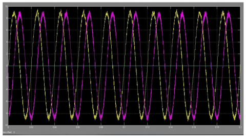
Figure 9. Signals waves results
The signals produced by the suggested system are shown in the accompanying figure, with 9.5 being the greatest signal and -9.5 representing the lowest.
The R-L load arrangement of a single-phase full-bridge inverter was tested experimentally in RT-Lab. The setups used power IGBTs as the inverter switches. When comparing the results for a single-phase full bridge inverter in RT-Lab and Matlab, it is clear that the two programs provide almost identical results. The Figure 10 show the Main circuit for single phase inverter were simulated and obtained the results in Figure 11 output current and voltage for single phase inverter.
Figure 10. Main circuit for single phase inverter
Figure 11. Output current and voltage for single phase inverter
To achieve good current regulation with little harmonic distortion, algorithms for predictive current regulation have been described that are amenable to practical application in a digital controller. The algorithms account for errors introduced by digital sampling delays and can be used in setups where the back emf is either directly measurable, as in PWM rectifier systems, or indirectly estimated from the measured current change in the previous switching cycles, as in a variable speed motor drive setup.
Can used in either single or three phase inverter systems, are very reliable, and provide accurate current regulation, even when overmodulated or out of tune. The effectiveness of the new algorithms has been shown via both simulation and experiment. The new VSI's predictive current control algorithm is first tested for its efficacy. As discussed in results section, that the higher thyristor is activated when the current flips from negative to positive, whereas the lower thyristor generates its triggering pulse when the current flips from positive to negative. The phase current exhibits a THD of 15% due to the mistake of switching signals computation brought on by the phase delay, constrains in this work its effecting of delaying phase currents have much less distortion at the zero-crossing point to solve this issue should utilizing a new method for predication for reaching to real value for current and voltage has a zero error rate. The main benefits are that the new concept can be used across the board for power conversion, the Z-source inverter is a buck boost inverter (something the more conventional V-source and I source inverters don't offer), it can be used in situations where the input voltage varies widely, all conventional PWM control schemes can be used, and the theoretical input-output relationship remains the same, and the cost is decreased and the efficiency is increased. The average switching device power of a Z-source inverter is lower in the low boost ratio band (1/2). The dc boosted PWM inverter is the optimal setup when operating at a low voltage and requiring a boost ratio greater than 2. The recognized RHP zero in the Z-source impedance network cannot be removed by modifying the Z-source values, which is a drawback. There is a need for more research on compensation strategies. In future directions we will try to predicate the value of current control by using different neural network algorithms and comparison the results with current study.
This study proposes a real-time method for managing the load current of a three-phase VSI system based on a DQ-comparator plus DQ coordinate. The load currents need not be converted to DQ coordinates; therefore, this control approach may provide quick tracking and a simple controller for controlling the current error within the hysteresis bands in ABC coordinate. MATLAB-Simulink was used to model a circuit. To understand how the DQ-comparator performed, a modeling method was used for controller development. Results from simulations and experiments that take into account the dynamic behavior of the DQ-comparator serve to confirm the system's performance. The primary aim of these constructions is to provide a source of three-phase voltage with adjustable voltage amplitude, phase, and frequency. To provide controlled frequency and AC voltage quantities utilizing pulse width modulation (PWM) techniques the optimal spot for inverter installation to minimize fifth-harmonic interference is. Furthermore, under ideal conditions, bus 6 remains the optimal site for inverter placement due to fifth-harmonic effects. Three-phase DC/AC voltage source transformers are often used in motor drives, active filters, and unified power flow controllers in power systems and uninterruptible power supplies to supply controlled frequency and AC voltage quantities.
[1] Ibrahim, A.M., Ibraheem, R.R., Weli, R.B. (2020). Energy saving in batteries using the photovoltaic system. Al-Kitab Journal for Pure Sciences, 4(1): 78-94. https://doi.org/10.32441/kjps.04.01.p7
[2] Bina, M.T. (2010). A transformerless medium-voltage STATCOM topology based on extended modular multilevel converters. IEEE Transactions on Power Electronics, 26(5): 1534-1545. https://doi.org/10.1109/TPEL.2010.2085088
[3] Ahmed, K.H., Aboushady, A.A. (2014). Modified half-bridge modular multilevel converter for HVDC systems with DC fault ride-through capability. In IECON 2014-40th Annual Conference of the IEEE Industrial Electronics Society, IEEE, pp. 4676-4682. https://doi.org/10.1109/IECON.2014.7049207
[4] Talon Louokdom, E., Gavin, S., Siemaszko, D., Biya-Motto, F., Essimbi Zobo, B., Marchesoni, M., Carpita, M. (2018). Small-scale modular multilevel converter for multi-terminal DC networks applications: System control validation. Energies, 11(7): 1690. https://doi.org/10.3390/en11071690
[5] Uddin, W., Zeb, K., Adil Khan, M., Ishfaq, M., Khan, I., Islam, S.U., Kim, H., Park, G.S., Lee, C. (2019). Control of output and circulating current of modular multilevel converter using a sliding mode approach. Energies, 12(21): 4084. https://doi.org/10.3390/en12214084
[6] Ben-Brahim, L., Gastli, A., Trabelsi, M., Ghazi, K.A., Houchati, M., Abu-Rub, H. (2016). Modular multilevel converter circulating current reduction using model predictive control. IEEE Transactions on Industrial Electronics, 63(6): 3857-3866. https://doi.org/10.1109/TIE.2016.2519320
[7] Li, Y.L., Jones, E.A., Wang, F. (2016). Circulating current suppressing control’s impact on arm inductance selection for modular multilevel converter. IEEE Journal of Emerging and Selected Topics in Power Electronics, 5(1): 182-188. https://doi.org/10.1109/JESTPE.2016.2617865
[8] Matas, J., de Vicuna, L.G., Miret, J., Guerrero, J.M., Castilla, M. (2008). Feedback linearization of a single-phase active power filter via sliding mode control. IEEE Transactions on Power Electronics, 23(1): 116-125. https://doi.org/10.1109/TPEL.2007.911790
[9] Moranchel, M., Bueno, E., Sanz, I., Rodríguez, F.J. (2017). New approaches to circulating current controllers for modular multilevel converters. Energies, 10(1): 86. https://doi.org/10.3390/en10010086
[10] Li, X.Q., Song, Q., Liu, W.H., Xu, S.K., Zhu, Z., Li, X.L. (2015). Performance analysis and optimization of circulating current control for modular multilevel converter. IEEE Transactions on Industrial Electronics, 63(2): 716-727. https://doi.org/10.1109/TIE.2015.2480748
[11] Li, B.Z., Huang, S.H., Chen, X., Wan, S.M. (2018). Enhanced DQ current control for single‐phase voltage‐source inverters. IET Power Electronics, 11(9): 1537-1546. https://doi.org/10.1049/iet-pel.2017.0747
[12] Liu, B.L., Zha, Y.B., Zhang, T. (2017). D-Q frame predictive current control methods for inverter stage of solid state transformer. IET Power Electronics, 10(6): 687-696. https://doi.org/10.1049/iet-pel.2016.0011
[13] Dou, W., Xu, Z.G., Peng, Y.C., Xu, H.H. (2009). Current controller design for three-phase photovoltaic grid-connected inverter. In Proceedings of ISES World Congress, Solar Energy and Human Settlement, Springer Berlin Heidelberg, pp. 1642-1646. https://doi.org/10.1007/978-3-540-75997-3_337
[14] Rodriguez, J., Pontt, J., Silva, C.A., Correa, P., Lezana, P., Cortés, P., Ammann, U. (2007). Predictive current control of a voltage source inverter. IEEE Transactions on Industrial Electronics, 54(1): 495-503. https://doi.org/10.1109/TIE.2006.888802
[15] Salih, A.B., Mahmood, Z.S., Ali, A.H.M., Nasret, A.N. (2022). Enhancement of motor speed identification using artificial neural networks. Indonesian Journal of Electrical Engineering and Computer Science (IJEECS), 27(3): 1388-1396. https://doi.org/10.11591/ijeecs.v27.i3.pp1388-1396
[16] Mahmood, Z.S., Nasret, A.N., Mahmood, O.T. (2021). Separately excited DC motor speed using ANN neural network. In AIP Conference Proceedings, AIP Publishing LLC, 2404(1): 080012. https://doi.org/10.1063/5.0068893
[17] Hamad, B.A., Ibraheem, A.M., Abdullah, A.G. (2020). Design and practical implementation of dual-axis solar tracking system with smart monitoring system. Przeglad Elektrotechniczny, 96(10): 151-155. https://doi.org/10.15199/48.2020.10.28
[18] Wu, C., Blaabjerg, F. (2021). Advanced control of power electronic systems-an overview of methods. Control of Power Electronic Converters and Systems, 1-33. https://doi.org/10.1016/B978-0-12-819432-4.00020-2
[19] Lu, M.Z., Hu, J.B., Zeng, R., He, Z.Y. (2017). Fundamental-frequency reactive circulating current injection for capacitor voltage balancing in hybrid-MMC HVDC systems during riding through PTG faults. IEEE Transactions on Power Delivery, 33(3): 1348-1357. https://doi.org/10.1109/TPWRD.2017.2755505
[20] Marchesoni, M. (1992). High-performance current control techniques for application to multilevel high-power voltage source inverters. IEEE Transactions on Power Electronics, 7(1): 189-204. https://doi.org/10.1109/63.124591
[21] Ahmed M.T. Ibraheem, A. (20). Speed control of three-phase induction motor based on V/F technique. Al-Kitab Journal for Pure Sciences, 1(1): 1-10. https://doi.org/10.32441/kjps.v1i1.85