Mohamed Islam Grairia*![]() | Riad Toufouti
| Riad Toufouti![]()
© 2023 IIETA. This article is published by IIETA and is licensed under the CC BY 4.0 license (http://creativecommons.org/licenses/by/4.0/).
OPEN ACCESS
This paper presents a hierarchical wireless control scheme for parallel distributed generation (DG) units in islanded AC microgrids. The proposed control scheme is divided into primary and secondary control layers. The primary control layer includes an improved finite set-model predictive control (FS-MPC) with a dual-objective cost function based on the proposed droop approach. The benefit of the proposed droop approach is the ability to generate the reference voltage without any amplitude deviation, unlike the conventional droop technique, which may cause deviations. Furthermore, double virtual impedances are proposed, with the first one being used to reduce the effects of feeders' mismatched impedance, while the second one is used to increase the output impedance resistance, leading to enhanced accuracy of active and reactive power sharing among DG units. The secondary control layer helps to establish global controllability by keeping the frequency and amplitude voltage of the AC bus at their nominal values. The simulation results show that the proposed control is capable of ensuring appropriate power sharing among parallel DG units and achieving voltage quality at the AC bus under different load conditions.
distributed generation, predictive control, power sharing, droop controller, double virtual impedances
In recent years, the depletion of nonrenewable sources and environmental pollution problems have increased in tandem with the rising demand for electricity. Therefore, developing microgrids based on distributed generation (DG) units, especially renewable energy sources (RES), has received significant interest for future modern power systems [1]. A typical microgrid is one of the foundational technologies of discrete power systems. Composed of distributed power sources, storage devices, power electronic converters, and controllable loads, it can operate autonomously (island mode) or in cooperation with a main grid (grid-connected mode) to provide an uninterrupted power supply for loads [2].
Figure 1. Microgrid configuration with several connected parallel DG units
In AC microgrids, the inverters are used to link these DG units to local loads or the grid, where these inverters are preferably operating in parallel, as shown in Figure 1. This offers the high dependability and system redundancy necessary for adaptable microgrid systems [3]. Several strategies for controlling parallel inverters, or more precisely, power sharing among different DG units, have been presented. They are divided into two categories based on whether or not they use control wire interconnections [4, 5]. In the first category, information signals must be exchanged among DG inverters, which leads to a complex structure of the microgrid and inhibits expansion, among the wired controls are master-slave control [6, 7], circular chain control [8], and average current sharing method [9, 10]. In the master-slave control, one of the inverters serves as the master, ensuring that the output voltage is produced with a constant frequency and amplitude, and the remaining inverters operate as slaves to follow the reference current specified by the master unit. Although this technique provides good output voltage and power sharing, the total dependence on the master and the communication among inverters reduce the reliability of the system. The second category of control is primarily founded on the droop control technique to address the issue of signal lines in wired interconnection control. The droop control technique utilizes only local measurements for each inverter. As a consequence, that offers higher dependability and flexibility in terms of the actual positioning of the units. This method entails dropping the frequency and amplitude of the output voltage in order to control the active and reactive power delivered by each inverter [11].
The droop control has several drawbacks that restrict its applicability range, including significant dependence on the inverter output impedance; amplitude and frequency deviations of the output voltage caused by the droop characteristics; and a slow dynamic response [12]. The conventional droop controller (P-f/Q-E) is most appropriate for high-voltage networks based on pure inductive line impedances. While in low-voltage distribution networks, the line impedances are mostly resistive [13], therefore, the conventional droop is ineffective, and in this case, the reverse droop controller (P-E/Q-f) must be implemented. The main difference between reverse droop control and conventional droop control is the direction in which the generator output is changed in response to frequency changes. Reverse droop control increases the output as the frequency increases, in contrast to conventional droop control, which decreases the output. In order to address the drawbacks of the conventional/ reverse droop technique, various improved droop approaches are proposed, including power angle droop control [14], a virtual flux-based technique [15], and a complex droop control technique [16]. In the study [14] high gain power angle enables better load sharing however it has a detrimental effect on overall stability. In the study [15] The power-sharing among DG units is achieved by decreasing the flux amplitude and adjusting the phase angle. Moreover, a direct flux control algorithm is presented to control the inverters and generate a defined flux from a droop controller. Hence, the control structure does not require multi-feedback loops or PWM modulators. Nonetheless, it's unclear how current limiting is applied. In the study [16], a new droop controller that takes into consideration the impact of complex impedance is presented. This controller can deliver superior power quality even when dealing with nonlinear loads and unbalanced line impedances.
In the presence of line impedance differences, the conventional/reverse droop technique is incapable of achieving accurate power distribution among parallel connected inverters. Several strategies, such as the virtual impedance technique, have been proposed to solve this issue [17, 18]. The virtual impedance technique compensates for these differences and ensures that power is shared equally among the inverters. This results in a stable and dependable power system with enhanced performance and reduced losses.
Over the past decade, the Model Predictive Control (MPC) method has gained widespread use in controlling power electronic converters thanks to its significant advantages over traditional linear control techniques. The MPC approach is based on predicting the future states of a controlled system using a modeled system [19]. One key benefit of this control technique is its ability to handle multi-objective optimization problems and easily manage system constraints [20]. However, it should be noted that MPC requires a higher number of calculations than linear control methods. Nonetheless, with the advent of fast microprocessors readily available on the market, implementing the MPC technique has become feasible.
Finite control set-model predictive control (FCS-MPC) represents a paradigm shift from traditional linear control techniques. Rather than designing loops for each controlled variable independently and then cascading them together, FCS-MPC utilizes the mathematical model of the power converter to predict the future behavior of variables and subsequently determines the optimal switching state based on a specified cost function [21].
This paper is structured as follows: In Section 2, an overview of power control using the droop control technique is provided. Section 3 offers the FCS-MPC strategy for a three-phase inverter with an LC filter. In addition, the proposed droop approach, double virtual impedances, and secondary control are presented. The simulation results of the scenario tests are shown in Section 4.
Droop control is a decentralized control approach that regulates the output voltage and frequency of voltage source inverters (VSIs) in AC microgrids. It mimics the behavior of a synchronous generator in a conventional power grid, and each VSI has an external power loop based on droop control. The power loop is responsible for sharing active and reactive power among DG units and improving system performance and stability by adjusting the frequency and voltage magnitude. One advantage of droop control is that it does not require communication among parallel inverters, making it a more reliable control strategy. Another advantage is that it allows for improved power sharing among DG units, reducing the risk of overloading and improving overall system efficiency.
Figure 2. A simplified diagram of two parallel inverters linked to the AC bus
Figure 2 illustrates two VSIs coupled via their output impedances to PCC on an AC microgrid bus. Typically, the output impedance of an inverter is inductive due to the presence of a large inductor filter and/or a high inductive line impedance. However, during low-voltage operations, the line impedance is mostly resistive. It is worth noting that control techniques can be employed to modify the output impedance, making it either resistive or inductive. In theory, a resistive output impedance (Z = R) is preferable, as it remains constant with frequency, and nonlinear loads' impact on the voltage THD is reduced. By assuming the output impedance to be resistive, we can express the active and reactive power supplied to the AC bus from each inverter as [22]:
$\left\{\begin{array}{l}P=\frac{E V}{R} \cos (\delta)-\frac{V^2}{R} \\ Q=-\frac{E V}{R} \sin (\delta)\end{array}\right.$ (1)
where, V and E are the amplitudes of the AC bus voltage and inverter output voltage, respectively; R is the inverter output resistance; and δ represents the phase angle between V and E.
Generally, the power angle is frequently extremely low (sin (δ) = δ and cos (δ) = 1). It's indeed evident that the inverter voltage amplitude has a significant impact on active power, whereas the phase angle has an effect on reactive power. Consequently, the characteristics describing the droop can be given in the following manner:
$E_d=E_o-k_v P$ (2)
$F_d=F_o+k_f Q$ (3)
where, Eo and Fo represent the amplitude and frequency of the output voltage with no load, kv and kf indicate the droop amplitude and frequency coefficients.
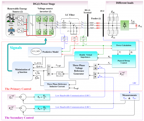
Figure 3 shows a comprehensive block diagram of the proposed power stage control of a DG unit with an LC filter connected in island mode, where the DG unit can consist of renewable and/or non-renewable generators. Furthermore, a variety of distributed loads are associated with an AC bus, including balanced, unbalanced, and nonlinear loads. The hierarchical control structure consists of two main levels of control. The first level is local control which is responsible for controlling active and reactive power and regulating the output voltage of the DG unit. The secondary level is a central control unit used to reduce voltage imbalance and harmonic distortion in the AC bus.
Figure 3. A comprehensive representation of the proposed control system of a DG unit within an island microgrid
The steps for implementing the proposed system can be outlined in the following manner:
3.1 Primary control
3.1.1 Power calculation
The measurement of instantaneous active and reactive power supplied by each DG unit is crucial for the effective management of three-phase power systems. To achieve this, the output voltage (Vo-abc) and output currents (Io-abc) of each DG unit are first measured in the a-b-c coordinates. These measurements are then transformed to the α-β coordinates using Clarke's transformation, as described in Eqns. (4) and (5). Once transformed to the α-β coordinates, the instantaneous active power (Pi) and reactive power (Qi) are calculated using Eq. (6) [23].
$\left[\begin{array}{l}V_\alpha \\ V_\beta\end{array}\right]=\sqrt{\frac{2}{3}}\left[\begin{array}{crc}1 & -\frac{1}{2} & -\frac{1}{2} \\ 0 & \frac{\sqrt{3}}{2} & -\frac{\sqrt{3}}{2}\end{array}\right]\left[\begin{array}{l}V_a \\ V_b \\ V_c\end{array}\right]$ (4)
$\left[\begin{array}{l}I_\alpha \\ I_\beta\end{array}\right]=\sqrt{\frac{2}{3}}\left[\begin{array}{rrr}1 & -\frac{1}{2} & -\frac{1}{2} \\ 0 & \frac{\sqrt{3}}{2} & -\frac{\sqrt{3}}{2}\end{array}\right]\left[\begin{array}{l}I_a \\ I_b \\ I_c\end{array}\right]$ (5)
$\left[\begin{array}{l}P_i \\ Q_i\end{array}\right]=\left[\begin{array}{cc}V_\alpha & V_\beta \\ V_\beta & -V_\alpha\end{array}\right]\left[\begin{array}{l}I_\alpha \\ I_\beta\end{array}\right]$ (6)
Instantaneous measurements of both active and reactive power (Pi and Qi) contain AC and DC components. The AC components are the oscillating parts caused by the harmonic and unbalanced components of the output voltage and current. On the other hand, the DC component represents the average value of active and reactive power and can be obtained using a low-pass filter with a 2 Hz cut-off frequency [24]. Hence, the average powers can be given as:
$\left\{\begin{array}{l}P=\frac{\omega_c}{1+\omega_c} P_i \\ Q=\frac{\omega_c}{1+\omega_c} Q_i\end{array}\right.$ (7)
where, $\omega_c$ is the low-pass filter's cut-off frequency.
3.1.2 Voltage reference generator
The effectiveness of using inductive output impedance as a control method to regulate the power delivered from DG units has been proposed in the study [12]. However, the sensitivity of the inductive output impedance to harmonics can significantly impact the power control system's performance. As a solution, a resistance output impedance is preferred over an inductive output impedance.
As mentioned previously, the droop control technique has an inherent connection between accuracy in power-sharing (P/Q) and amplitude/frequency control of the output voltage. From Eq. (1), it is obvious that the active power can also be controlled by varying the output resistance's value. In considering the fact that P decreases as R increases, we propose utilizing an adaptive output impedance that enhances the resistivity of each DG's output impedance, which is given by:
$R_d=R_d^{r e f}-k_R P$ (8)
where, $R_d^{r e f}$ is the reference output resistance, and kR is the active power coefficient which modifies the resistive output impedance.
The significance of this proposed approach is that the control of active power can be achieved using the resistance output impedance while keeping the reference amplitude voltage constant, in contrast to the reverse droop method, which results in reference voltage deviation (see Eq. (2)). The reference voltage before applying the virtual impedance can be determined using the following equation:
$V_{\text {ref }}^{\text {old }}=\left\{\begin{array}{l}E_{p c c}^{r e f} \sin \left(2 \pi F_d t\right) \\ E_{p c c}^{r e f} \sin \left(2 \pi F_d t-2 \pi / 3\right) \\ E_{p c c}^{r e f} \sin \left(2 \pi F_d t+2 \pi / 3\right)\end{array}\right.$ (9)
where, $E_{p c c}^{r e f}$ is the reference amplitude of the PCC bus, and Fdis the frequency determined by Eq. (3) which is used to control the reactive power.
3.1.3 Double virtual impedances
The equivalent output impedance of the inverter plays a major role in achieving accurate and balanced power sharing, as the equivalent output impedance is affected by several variables, including feeder impedance, voltage/current control loop parameters, and filter parameters. Hence, any mismatch in these variables leads to inaccurate power sharing [25]. As a result, the virtual impedance concept has emerged as a required condition to overcome these problems. In general, the virtual output impedance is adjusted to overcome the dominant line impedance and make the equivalent output impedance identical for all inverters in the microgrid.
Voltage deviations. Although balanced power sharing can be accomplished with virtual impedance, its faulty design can result in significant voltage drops. As a result, this section will provide the virtual impedance design method that can minimize voltage drops using the summing approach as follows [3]:
$V_{\text {drop } 1}=\left(Z_{l 1}+Z_{v 1}\right) I_{l 1}=V_{\text {dropk }}=\left(Z_{l k}+Z_{v k}\right) I_{l k}$ (10)
where Zlk and Zvk are the line impedance and the virtual output impedance of the inverter (k), respectively.
The control rules used in the summation approach to adjust the virtual output impedances' optimization values of 1 ... kth inverters are expressed by assuming that Zl1 is larger than the others, Zl1 > Zlk, allowing Zv1 = 0 to be chosen. Hens, Eq. (10) can be changed to the following form:
$Z_{v k}=\left(Z_{l 1}-Z_{l k}\right)$ (11)
The impedance information of each feeder must be known, either by obtaining the cable specifications or through the use of an online impedance estimation technique [26, 27].
The voltage drop caused by the virtual impedance of each DG unit is expressed by:
$\Delta V_{v k-a b c}=Z_{v k} I_{k o, a b c}$ (12)
where,
$Z_{v k}=\left(R_{v k}+j \omega L_{v k}\right)$ (13)
By applying the park transform to convert Eq. (12) to a dq reference frame, yielding Eq. (14):
$\left[\begin{array}{c}\Delta V_{v_{-} d} \\ \Delta V_{v_{-} q}\end{array}\right]=R_{v k}\left[\begin{array}{c}I_d \\ I_q\end{array}\right]+L_{v k} s\left[\begin{array}{c}I_d \\ I_q\end{array}\right]+\left[\begin{array}{cc}0 & -\omega L \\ \omega L & 0\end{array}\right]\left[\begin{array}{c}I_d \\ I_q\end{array}\right]$ (14)
To implement the virtual impedance with the proposed droop approach, the output current is used in fast negative feedback, resulting in a drop in the reference voltage. As a consequence, the reference voltage produced by each inverter is changed as follows:
$V_{r e f}^{\text {new }}=V_{r e f}^{\text {old }}-Z_{v k} I_{k o-a b c}$ (15)
Adaptive virtual impedance loop. The virtual resistance improves the damping of the oscillation system without introducing power loss or decreasing the efficiency of the system. In addition, the virtual resistance makes the output impedance of each DG unit more resistive, which leads to an enhancement in the decoupling between active and reactive power, improves the stability of the system, and reduces circulating currents and power oscillations [28]. As a result of these reasons, an adaptive virtual impedance was proposed by modifying Eq. (15) to Eq. (16). The detailed implementation of the dual virtual impedances is shown in Figure 4. The low-pass filter is used to reduce the impact of high-frequency oscillations caused by the derivative term.
$V_{r e f}^{n e w}=V_{r e f}^{o l d}-Z_{v k} I_{k o-a b c}-R_d I_{k o-a b c}$ (16)
Figure 4. Proposed droop control with double virtual impedances
3.1.4 Output voltage regulation
In the context of parallel inverters, there are two main strategies of MPC techniques that can be used, each with its own distinct features and advantages: continuous control set MPC (CCS-MPC) and finite control set MPC (FCS-MPC). CCS-MPC requires a modulator to supply the required voltage, leading to a fixed switching frequency. This limitation can result in higher switching losses and lower efficiency. In contrast, FCS-MPC utilizes the finite number of switching possibilities of the converter to solve optimization problems, offering greater flexibility in terms of the switching frequency. This results in improved efficiency and reduced switching losses. However, FCS-MPC implementation can be more complex than CCS-MPC, as an optimization problem must be solved at every sampling time [29].
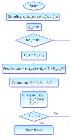
In FCS-MPC, the mathematical model of the system is used to predict how potential variables will respond at the next sampling time (N = 1), and the cost function is used to obtain the desired control objectives. To apply this technique for VSI, both models of the three-phase inverter and the LC filter are required. There are eight voltage vectors available for a three-phase, two-level (3Ph-2L) inverter, including two zeros (0,7) and six active vectors (1-6), which are shown in Figure 5 and can be given by Eq. (17). The selection of the appropriate voltage vector (Vi) is based on the predicted output voltage and current errors at the next sampling time, which are determined by solving an optimization problem with an appropriate solver.
$V_i=\frac{2}{3} V_{d c} e^{i(j-1) \frac{\pi}{3}}, \quad j=0 ; \ldots ; 7$ (17)
where, Vdcis the DC link voltage.
Figure 5. Voltage vector options for inverter systems
The dynamic behavior of the inverter LC filer capacitor can be represented as:
$C \frac{d V_c}{d t}=I_f-I_o$ (18)
The mathematical model for filter inductance is as follows:
$L \frac{d I_f}{d t}=V_i-V_c$ (19)
By combining Eq. (18) and Eq. (19), the continuous-time state-space model of the system can be expressed by:
$\frac{d x}{d t}=A x+B V_i+B_d I_0$ (20)
where,
$x=\left[\begin{array}{l}I_f \\ V_c\end{array}\right], A=\left[\begin{array}{cc}0 & -1 / L \\ 1 / C & 0\end{array}\right], B=\left[\begin{array}{c}1 / L \\ 0\end{array}\right], B_d=\left[\begin{array}{c}0 \\ -1 / C\end{array}\right]$
The discrete-time LC filter model for sampling time Ts is required for the implementation of the proposed control digital algorithm, which is given by:
$x(k+1)=A_q x(k)+B_q V_i(k)+B_{d q} I_o(k)$ (21)
where,
$\left\{\begin{array}{l}B_q=\int_0^{T_s} e^{A \tau} B d \tau \\ A_q=e^{A T_s} \\ B_{d q}=\int_0^{T_s} e^{A \tau} B_d d \tau\end{array}\right.$ (22)
Generally, the sampling time Ts is quite small; therefore, the approximate of the first-order derivative calculation by forward Euler is given as:
$\frac{d x}{d t} \approx \frac{x(k+1)-x(k)}{T_s}$ (23)
By substituting Eq. (23) into Eq. (20), the future behavior values of the capacitor voltage and the inductance current are given by:
$\left\{\begin{array}{l}V_c(k+1)=V_c(k)+\frac{T_s}{C}\left(I_f(k)-I_o(k)\right) \\ I_f(k+1)=I_f(k)+\frac{T_s}{C}\left(V_i(k)-V_c(k)\right)\end{array}\right.$ (24)
Consequently, the prediction model uses the actual values of Vc(k), If (k), and Io(k) to determine the predicted capacitor voltage and the inductance current at the next sampling time (k + 1).
Two cost functions have been established to deal with the required control objectives. The first one aims to minimize the difference between the reference voltage and the capacitor voltage. While the second cost function is employed to track the reference inductor current, which leads to regulating the load current when a fault occurs. By combining these two cost functions, the total cost function can be defined as:
$g_t=\lambda_v g_v+\lambda_i g_i$ (25)
where, λv and λi are the weighting factors, and the expressions of gv and gi are given as follows:
$\left\{\begin{array}{l}g_v=\left(V_{\text {ref }}^{\text {new }}-V_c(k+1)\right)^2 \\ g_i=\left(I_{\text {ref }}^{\text {new }}-I_f(k+1)\right)^2\end{array}\right.$ (26)
The reference inductance current is determined by applying Kirchhoff's Law, as shown below:
$I_{r e f}^{\text {new }}=j C \omega V_{r e f}^{\text {new }}+I_o$ (27)
To determine the optimal voltage vector Vi for the inverter, a systematic process is followed. Initially, predictions are generated for future values of Vc(k + 1) and If (k + 1), resulting in eight possible predictions. These predictions are compared to their respective references using a proper cost function (Eq. (25)). By minimizing this cost function, the optimal voltage vector Vi is selected for application by the inverter at the next sampling instant. To gain a better understanding of the process, a flowchart presented in Figure 6 has been provided to summarize the steps outlined below.
Figure 6. Switch selection algorithm for VSI using MPC
Figure 7. N=2: (a) voltage vectors are varied at each sampling time. (b) The same voltage vector is used for two consecutive sampling times
In power generation, the efficiency of the system is significantly influenced by the converter's switching frequency, as a high switching frequency leads to increased losses. Therefore, in order to overcome this problem and achieve a low switching frequency, an improved MPC with a two-step prediction horizon (N=2) is proposed in [30, 31]. Whenever two steps are considered for the prediction, two voltage vectors are evaluated. For the first sample period, one of these vectors is selected, and for the second sample period, another vector is used. Hence, 49 different voltage vector combinations are feasible and can be obtained, as shown in Figure 7(a). However, the experimental implementation of this algorithm might be exceedingly challenging due to the enormous number of computations required. For this reason, a modified algorithm is employed, which is based on the same voltage vector used in both two sampling times, as depicted in Figure 7(b). Hence, at both sampling periods, just seven voltage vectors rather than 49 are considered. This results in a decrease in switching frequency, a lowering of voltage ripples, and an improved waveform quality.
3.2 Secondary control
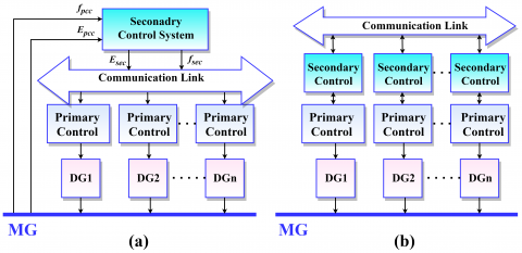
The secondary control (SC) is added to the primary control to achieve high controllability of the microgrid, which is developed to restore the frequency and amplitude voltage deviations at the AC bus. SC techniques may be employed in either centralized or decentralized form, as shown in Figure 8. A centralized approach typically involves estimating the voltage (Epcc) and frequency (fpcc) of the AC bus which are then compared to their respective reference values. The resulting error signals are processed by a PI controller, which subsequently transmits corrective signals to all DG units, as expressed in Eq. (28) and shown in Figure 8(a). In contrast, a decentralized control strategy, as depicted in Figure 8(b), equips each DG unit with SC capabilities to independently correct voltage and frequency deviations.
$\left\{\begin{array}{l}f_{\mathrm{sec}}=k_{p f}\left(f_{p c c}^{r e f}-f_{p c c}\right)+k_{i f} \int\left(f_{p c c}^{r e f}-f_{p c c}\right) d t \\ E_{\mathrm{sec}}=k_{p v}\left(E_{p c c}^{r e f}-E_{p c c}\right)+k_{i v} \int\left(E_{p c c}^{r e f}-E_{p c c}\right) d t\end{array}\right.$ (28)
where, kpf, kif, kpv and kiv are the secondary control parameters of the frequency and amplitude compensator.
The accurate tuning of proportional-integral (PI) gains is a critical and challenging task, particularly with respect to guaranteeing improved system performance and power quality during the operation of DG units and load changes. To address this issue, an improved SC mechanism is proposed [32]. This control strategy employs an optimized PI controller based on a combination of genetic algorithms (GA) and artificial neural networks (ANNs). By leveraging this advanced computational technique, the proposed control mechanism is able to dynamically adjust the PI controller gains, resulting in more effective regulation of the microgrid's frequency and voltage levels.
Figure 8. Secondary control: (a) Centralized (b) Decentralized
To validate the proposed hierarchy for power-sharing control, a microgrid operating in island mode is utilized, consisting of two parallel DG units connected in parallel to the PCC of an AC bus with different line impedances. This configuration is illustrated in Figure 9, and the control parameters used in the simulation are listed in Table 1. Several scenarios were investigated to verify the efficiency of this control under different conditions, including linear, non-linear, and unbalanced loads.
Figure 9. Microgrid structure test
Table 1. Power stage and control parameters
|
System Parameter |
Value |
|
LC Filter |
L = 4 mH, C = 200 µF |
|
DC Link Voltage |
700 V |
|
DG feeder |
DG1 feeder : Rl1 = 0.5 Ω, Ll1= 0.4 mH DG2 feeder : Rl2 = 0.3 Ω, Ll2= 0.2 mH |
|
FCS-MPC |
Value |
|
Sampling time |
Ts=30 µs |
|
weight factor |
$\lambda_v$= 1 , $\lambda_i$= 1.2 |
|
Power Control Parameter |
Value |
|
$R_d, k_R, k_f$ |
1 Ω, 4.10-4, 5.10-4 |
|
$k_{p f}, k_{i f}, k_{p v}, k_{i v}$ |
0.5, 10 s-1, 0.3, 12 s-1 |
|
Load Parameter |
Value |
|
Balanced Load |
RBL = 25 Ω, LBL = 4 mH |
|
Unbalanced Load |
RUL1= 30 Ω , RUL2= 20 Ω, RUL3= 40 Ω |
|
Non-Linear Load |
RNL = 50 Ω , LNL= 1 mH |
4.1 Steady-state and load transients (linear RL load)
Figures 10(a–h) present the results of the first test, in which a linear RL load with 10 kW of active power and 6 kVAR of reactive power is applied for t < 0.3 s. To evaluate the impact of changes in load on the proposed droop control, the load is increased to 20 kW and 12 kVAR at t >= 0.3 s.
Figure 10(a) illustrates the three-phase voltage waveform of the load, which remains stable in amplitude (311 V phase to ground) and frequency at 50 Hz. The proposed control method, which utilizes a dual-objective control function, effectively eliminates the error between the instantaneous output voltage and the reference voltage, even with an increase in load at t = 0.3 s.
The results shown in Figures 10(b-d) indicate that, initially, the currents supplied by both DG units were similar, and the load current was the sum of the output currents of DG1 and DG2. However, when the virtual impedance was removed at t = 0.6 s, the output currents of each DG unit began to differ, which can result in circulating currents between the inverters.
Figure 10(e) shows that the load voltage has a total harmonic distortion (THD) of 0.08%, indicating a low level of harmonic distortion in the voltage waveform. This value is within the IEEE-519 standard limit of 5% [33].
Figure 10(f-h) illustrate the active and reactive powers of the DG units and load, respectively. It is evident that for t < 0.6 s, each DG unit generates half of the total load power, indicating that the inverters share power equally. Additionally, the system exhibits a rapid response when the load increases at t = 0.3 s, indicating the proposed control's efficient performance against load variations. However, as mentioned in Section 1, the active and reactive powers are significantly influenced by the line impedance, as seen at t = 0.6 s. The removal of the virtual impedance results in a power-sharing imbalance between the inverters due to the mismatch of feeder impedances between each DG unit.
Figure 10. The results of the first test: (a) load voltage; (b) DG1 output current; (c) DG2 output current; (d) load current; (e) THD load voltage;(f) DG1/DG2 active power; (g) DG1/DG2 reactive power; (h) load active and reactive power
Figure 11. AC bus voltage: (a) frequency response; (b) amplitude response
Figures 11(a) and (b) illustrate the frequency and amplitude response of the AC bus voltage, which also represents the load voltage. These figures provide a detailed representation of the voltage characteristics, allowing for a comprehensive analysis.
Figure 11(a) demonstrates that the frequency is stable at 50 Hz. However, under increased load conditions at t = 2s, a corresponding increase in frequency is observed due to the relation between reactive power and frequency. Specifically, increasing reactive power leads to a change in the voltage phase angle, which in turn affects the system frequency. Nonetheless, the implementation of secondary control can mitigate this effect by eliminating this deviation. Figure 11(b) illustrates the response of the amplitude voltage, indicating a small deviation at t = 2 s due to the increase in load current, which leads to a corresponding increase in the voltage droop of the virtual impedance. However, the secondary control mechanism effectively restores the amplitude voltage to its nominal value (311 V).
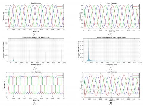
4.2 Performance test against non-Linear and unbalanced loads
To assess the performance of the proposed control strategy under non-linear and unbalanced loads, two tests were conducted. In the first test, SW2 and SW3 were open while SW1 was closed, connecting a non-linear load to the PCC. Figure 12 (a and c) display the voltage and current of the non-linear load, respectively. It is apparent from Figure 12(a) that the voltage stayed stable as a sine wave despite the presence of distorted output currents shown in Figure 12(c). In the second test, SW3 was closed, connecting an unbalanced load to PCC, while SW1 and SW2 were opened. Although the load currents shown in Figure 12 (f) were unbalanced, the voltage at the AC bus remained stable in amplitude and frequency, as illustrated in Figure 12(d).
Figure 12 (b and e) indicate that the THD of the load voltage is consistently low in both scenarios.
The third test involved the sequential connection of a non-linear load, an unbalanced load, and a linear load to the PCC. As depicted in Figure 13 (a and b), the transition responses of the output voltage and current in the AC bus were analyzed for each load condition. Despite the changes in load type, the voltage at the AC bus remained stable throughout the tests, indicating the efficiency of the proposed control strategy in regulating voltage. The transition responses of the output current were also observed to be rapid, suggesting the resilience of the control system.
In Table 2, a comparison is made between the current MPC systems that use the droop control technique and the proposed control technique based on information gathered from the literature and the results obtained in Figure 10(e) and Figure 12(b and e), the proposed control method exhibits superior dynamic response and effectively minimizes the impact of harmonics, resulting in better overall performance compared to other controllers studied in the literature.
Figure 12. The results of the second test: (a) non-linear load voltage; (b) THD non-linear load voltage; (c) non-linear load current; (d) unbalanced load voltage; (e) THD unbalanced load voltage; (f) unbalanced load current
Figure 13. The results of the third test: (a) load voltage; (b) load current
Table 2. Comparison of different control methods in terms of voltage quality
|
Reference Year |
Type of technique |
Voltage THD under |
|
|
|
|
Linear Load |
Non-Linear Load |
|
[34] | 2021 |
FS-MPC-based arctan droop control |
1.23% |
/ |
|
[30] | 2021 |
FS-MPC-Based Conventional droop control |
0.89% |
1.40% |
|
[35] | 2022 |
FS-MPC Based virtual synchronous generator |
0.35% |
/ |
|
[29] | 2023 |
a fixed-switching-frequency M2PC Based Conventional droop |
1.53% |
/ |
|
Proposed |
FS-MPC-based proposed droop approach |
0.08% |
0.72% |
In this research, a proposed droop approach is presented for controlling parallel three-phase inverters connected to an AC bus under different conditions, including linear and nonlinear loads. This approach controls the active power by the output impedance, and its novelty lies in its ability to address the limitations and challenges of existing methods as well as offer new capabilities and benefits. Specifically, it uses FCS-MPC to ensure proper tracking of the output voltage of each inverter to the reference values with robust, fast transient, and stable steady-state responses. Dual virtual impedances are also used to reduce the impact of feeders' mismatched impedances and improve power sharing among DG units. The simulation results demonstrate the efficacy of this proposed approach under diverse conditions, including enhanced power sharing and voltage stabilization at the PCC.
As a perspective, the study can be extended to more complex power system configurations, such as hybrid DC-AC microgrids and interconnected grids, to address the increasing demand for sustainable power systems. Future research can also investigate the feasibility of implementing the proposed approach in real-world applications, taking into account practical constraints such as hardware limitations and communication delays. These research directions can help pave the way for a more efficient, resilient, and sustainable power system in the future.
[1] Ellabban, O., Abu-Rub, H., Blaabjerg, F. (2014). Renewable energy resources: Current status, future prospects and their enabling technology. Renewable and Sustainable Energy Reviews, 39: 748-764. https://doi.org/10.1016/j.rser.2014.07.113
[2] Vasquez, J.C., Guerrero, J.M., Miret, J., Castilla, M., Garcia de Vicuna, L. (2010). Hierarchical control of intelligent microgrids. IEEE Industrial Electronics Magazine, 4(4): 23–29. https://doi.org/10.1109/mie.2010.938720
[3] Tayab, U.B., Roslan, M.A.B., Hwai, L.J., Kashif, M. (2017). A review of droop control techniques for microgrid. Renewable and Sustainable Energy Reviews, 76: 717–727. https://doi.org/10.1016/j.rser.2017.03.028
[4] Guerrero, J.M., de Vicuna, L.G., Miret, J., Matas, J., Cruz, J. (2004). Output impedance performance for parallel operation of UPS inverters using wireless and average current-sharing controllers. 2004 IEEE 35th Annual Power Electronics Specialists Conference, Aachen, Germany: 2482-2488 https://doi.org/10.1109/pesc.2004.1355219
[5] Asadi, Y., Eskandari, M., Mansouri, M., Savkin, A.V., Pathan, E. (2022). Frequency and voltage control techniques through inverter-interfaced distributed energy resources in microgrids: A review. Energies, 15(22): 8580. https://doi.org/10.3390/en15228580
[6] Pei, Y., Jiang, G., Yang, X., Wang, Z. (2004). Auto-master-slave control technique of parallel inverters in distributed AC power systems and UPS. In 2004 IEEE 35th Annual Power Electronics Specialists Conference, Aachen, Germany: 2050–2053. https://doi.org/10.1109/pesc.2004.1355433
[7] Jeong, B. (2022). Modified master-slave controller for stable power supply of energy storage based microgrid. Energies, 15(12): 4245. https://doi.org/10.3390/en15124245
[8] Wu, T.F., Chen, Y.K., Huang, Y.H. (2000). 3C strategy for inverters in parallel operation achieving an equal current distribution. IEEE Transactions on Industrial Electronics, 47(2): 273-281. https://doi.org/10.1109/41.836342
[9] Chen, Y.K., Wu, T.F., Wu, Y.E., Ku, C.P. (2001). A current-sharing control strategy for paralleled multi-inverter systems using microprocessor-based robust control. Proceedings of IEEE Region 10 International Conference on Electrical and Electronic Technology, Singapore, 2: 647–653. https://doi.org/10.1109/TENCON.2001.949673
[10] Xing, Y., Huang, L., Sun, S., Yan, Y. (2002). Novel control for redundant parallel UPSs with instantaneous current sharing. Proceedings of the Power Conversion Conference, Osaka, Japan, 3: 959-963. https://doi.org/10.1109/pcc.2002.998098
[11] Feddaoui, O., Toufouti, R., Djamel, L., Meziane, S. (2020). Active and reactive power sharing in micro grid using droop control. International Journal of Electrical and Computer Engineering (IJECE), 10(3): 2235. https://doi.org/10.11591/ijece.v10i3.pp2235-2244
[12] Guerrero, J. M., GarciadeVicuna, L., Matas, J., Castilla, M., Miret, J. (2005). Output impedance design of parallel-connected ups inverters with wireless load-sharing control. IEEE Transactions on Industrial Electronics, 52(4): 1126–1135. https://doi.org/10.1109/tie.2005.851634
[13] John, B., Ghosh, A., Zare, F. (2017). Droop control in low voltage islanded microgrids for sharing nonlinear and unbalanced loads IEEE Region 10 Symposium, Cochin, India: 1-5. https://doi.org/10.1109/tenconspring.2017.8069980
[14] Majumder, R., Chaudhuri, B., Ghosh, A., Majumder, R., Ledwich, G., Zare, F. (2010). Improvement of stability and load sharing in an autonomous microgrid using supplementary droop control loop. IEEE PES General Meeting, 25: 796-808. https://doi.org/10.1109/pes.2010.5589665
[15] Hu, J., Zhu, J., Qu, Y., Guerrero, J.M. (2013). A new virtual-flux-vector based droop control strategy for parallel connected inverters in microgrids. IEEE Trans. Power Electron. 29: 4704-4711. https://doi.org/10.1109/ecce-asia.2013.6579157
[16] Yao, W., Chen, M., Matas, J., Guerrero, J.M., Qian, Z.M. (2011). Design and analysis of the droop control method for parallel inverters considering the impact of the complex impedance on the power sharing. IEEE Transactions on Industrial Electronics, 58(2): 576–588. https://doi.org/10.1109/tie.2010.2046001
[17] Lyu, Z., Wei, Q., Zhang, Y., Zhao, J., Manla, E. (2018). Adaptive virtual impedance droop control based on consensus control of reactive current. Energies, 11(7): 1801. https://doi.org/10.3390/en11071801
[18] He, J., Li, Y.W. (2011). Analysis, design, and implementation of virtual impedance for power electronics interfaced distributed generation. IEEE Transactions on Industry Applications, 47(6): 2525–2538. https://doi.org/10.1109/tia.2011.2168592
[19] Mohamed, I.S., Zaid, S.A., Elsayed, H.M., Abu-Elyazeed, M.F. (2013). Three-phase inverter with output LC filter using predictive control for UPS applications. 2013 International Conference on Control, Decision and Information Technologies (CoDIT) , Hammamet, Tunisia: 489-494. https://doi.org/10.1109/codit.2013.6689593
[20] Karamanakos, P., Liegmann, E., Geyer, T., Kennel, R. (2020). Model predictive control of power electronic systems: methods, results, and challenges. IEEE Open Journal of Industry Applications, 1: 95-114. https://doi.org/10.1109/ojia.2020.3020184
[21] Bayhan, S., Trabelsi, M., Abu-Rub, H., Malinowski, M. (2017). Finite-control-set model-predictive control for a quasi-z-source four-leg inverter under unbalanced load condition. IEEE Transactions on Industrial Electronics, 64(4): 2560-2569. https://doi.org/10.1109/tie.2016.2632062
[22] Zhong, Q.C. (2013). Robust droop controller for accurate proportional load sharing among inverters operated in parallel. IEEE Transactions on Industrial Electronics, 60(4): 1281-1290. https://doi.org/10.1109/tie.2011.2146221
[23] Mikulović, J., Šekara, T., Forcan, M. (2023). Power definitions for three-phase systems in terms of instantaneous symmetrical components. International Journal of Electrical Power & Energy Systems, 147, 108808. https://doi.org/10.1016/j.ijepes.2022.108808
[24] Han, Y., Shen, P., Zhao, X., Guerrero, J.M. (2016). An enhanced power sharing scheme for voltage unbalance and harmonics compensation in an islanded ac microgrid. IEEE Transactions on Energy Conversion, 31(3): 1037–1050. https://doi.org/10.1109/tec.2016.2552497
[25] Raj D,C., Gaonkar, D.N., Guerrero, J.M. (2018). Improved P-f/Q-V and P-V/Q-f droop controllers for parallel distributed generation inverters in AC microgrid. Sustainable Cities and Society, 41: 421–442. https://doi.org/10.1016/j.scs.2018.04.026
[26] Mohammed, N., Ali, M., Ciobotaru, M., Fletcher, J. (2023). Accurate control of virtual oscillator-controlled islanded AC microgrids. Electric Power Systems Research, 214: 108791. https://doi.org/10.1016/j.epsr.2022.108791
[27] Mohammed, N., Ciobotaru, M. (2020). An accurate reactive power sharing strategy for an islanded microgrid based on online feeder impedance estimation. IECON 2020 The 46th Annual Conference of the IEEE Industrial Electronics Society. https://doi.org/10.1109/iecon43393.2020.9255394
[28] Savaghebi, M., Vasquez, J.C., Jalilian, A., Guerrero, J.M., Lee, T.L. (2013). Selective compensation of voltage harmonics in grid-connected microgrids. Mathematics and Computers in Simulation, 91: 211–228. https://doi.org/10.1016/j.matcom.2012.05.015
[29] Villalón, A., Muñoz, C., Muñoz, J., Rivera, M. (2023). Fixed-switching-frequency modulated model predictive control for islanded AC microgrid applications. Mathematics, 11(3): 672. https://doi.org/10.3390/math11030672
[30] Khan, H. S., Aamir, M., Kauhaniemi, K., Mumtaz, M., Hassan, M. W., Ali, M. (2021). Improved finite control set model predictive control for distributed energy resource in islanded microgrid with fault-tolerance capability. Engineering Science and Technology, an International Journal, 24(3): 694-705. https://doi.org/10.1016/j.jestch.2020.12.015
[31] Mohamed, I.S., Zaid, S.A., Elyazeed, M.F.A., Elsayed, H.M. (2015). Improved model predictive control for three-phase inverter with output LC filter. International Journal of Modelling, Identification and Control, 23(4): 371. https://doi.org/10.1504/ijmic.2015.070642
[32] Jasim, A.M., Jasim, B. H., Bureš, V., Mikulecký, P. (2022). A New decentralized robust secondary control for smart islanded microgrids. Sensors, 22(22), 8709. https://doi.org/10.3390/s22228709
[33] Akdogan, M.E., Ahmed, S. (2020). Control hardware-in-the-loop for voltage controlled inverters with unbalanced and non-linear loads in stand-alone photovoltaic (PV) islanded microgrids. 2020 IEEE Energy Conversion Congress and Exposition (ECCE). https://doi.org/10.1109/ECCE44975.2020.9235913
[34] Iyakaremye, J.D.D., Nyakoe, G.N., Wekesa, C.W. (2021). MPC-based arctan droop control strategy of the parallel inverter system in an islanded AC microgrid. Journal of Engineering, 2021, 1-13. https://doi.org/10.1155/2021/1870590
[35] Abou-Hussein, W.M., Dabour, S.M., Hamad, M.S., Rashad, E. M. (2023). Model predictive control based virtual synchronous generator for parallel-connected three-phase split-source converters in islanded AC Microgrids. Energy Reports, 9, 1696-1706. https://doi.org/10.1016/j.egyr.2022.12.075