AlZahraa N. Fawzi* | Maher Y. Salloom![]()
© 2023 IIETA. This article is published by IIETA and is licensed under the CC BY 4.0 license (http://creativecommons.org/licenses/by/4.0/).
OPEN ACCESS
Industrial processes need to be adjusted fast in order to generate a variety of products. The response to these modifications, the pneumatic control must be rebuilt in accordance with the new requirements, i.e., the control mechanism must be rebuilt. These issues could be resolved by utilizing the Karnaugh mapping method. The objective of this work is to develop multiple-actuator pneumatic circuits and reduce start-up times by merging various operational sequences into a single process. The Karnaugh maps is a technique for reducing logical equations or transforming truth tables into logic circuits. The method allows for circuit control using a programmable controller (PLC). One of the key advantages of using the suggested technique is the ease with which electrical schematic command circuits may be obtained. Schema will be created by simply using the pneumatic cylinder motion equations that were acquired from the Karnaugh map. The suggested technique assures not only the intended sequential cycle but also the minimizing of control command variables. This study focuses use Karnaugh Maps to develop a pneumatic control system in difficult cases with three different control sequences for five cylinders. Simulation software for pneumatic/electro-pneumatic circuits is utilized to apply the technique (Automation Studio and Fluid Sim). By applying the suggested rules, the logic equations were extracted in a simpler form, and they are simple to use pneumatically and electro pneumatically. It is also easily converted to Ladder Diagram Language. This method allows us to fast work in production cycles.
karnaugh maps, programmable logic controller PLC, sequential pneumatic circuits, control of ON/OFF, industrial automation, multiple pneumatic actuator
One of the earliest sources of energy is compressed air. Its distribution and use under various working conditions have become ubiquitous, and it is now as essential component found in all product and service industries. Compressed air has been used as a power source since the beginning of humanity. It was used for the first time in 250 BC. By replacing human strength with compressed air, high production rates are made possible with a consistent and constant output capacity. Combining this type of energy allows for parallel operation of oil-hydraulic systems, mechanical, electrical, and electronic systems. The regulated use of this energy source was dubbed pneumatic (Pneuma), a Greek word that means "to blow or to breathe". Used in a variety of operations such as drilling, riveting, deburring, filling and capping, and so on, they are perfect for process automation. Pneumatic control can be done pneumatically, electrically, electronically (e.g., PLC), or in conjunction with hydraulics as a power supply and control, or vice versa. Automating sequential procedures is common in pneumatics. The term "automation" refers to the process of turning a manual process into an automated one, hence reducing human labor and increasing productivity. Only when industries adopt high-end technology accessible on the market will they be productive. As a result, industries will take a step ahead into the era of modern industrialization by incorporating PLCs into their operations. In the area of automation, PLC is extremely significant [1]. Integrated circuits (ICs) are used by Programmable Logical Controllers (PLCs), which are hard component members of the PC family, to carry out control functions instead of electromechanical devices. In order to regulate mechanical devices and processes, they are able to store instructions for example rules for the sequencing, timing, calculation, information control, and interfaces communication [2, 3].
When sequential operations need to be automated, pneumatics becomes difficult. Industrial applications frequently use pneumatic processes sequence (PPS) to complete a given larger work inside an industrial application [4]. By alternately rerouting compressed air in the actuator chambers, the actuators may be moved pneumatically in either a translational or a rotational direction. Because of this, the flow of air that is compressed through the actuator chambers is controlled by directional control valves in an alternative manner. The directional valve makes sure that air from the opposing chamber may exit. In this sense, the direction of the actuators' motions is controlled to carry out the prescribed sequences, whether they be sequential or combinatorial cycles. Therefore, was build a pneumatic circuit control system using KM’s methodology.
The proposed technique, by adhering to the methodology's criteria, not only ensures the execution of the required sequential pneumatic cycle but additionally allows for electrical control of the PLC and the direct implementation of the orders obtained by using the Karnaugh method. The electric control circuit is created directly utilizing the pneumatic cylinders' equations of motion that were obtained through the Karnaugh map. One of the most crucial methods for learning is a simulation it makes education affordable and offers the greatest way to help students develop their practical abilities [5]. The potential of this approach for education in engineering, in particular at the level of pneumatic automation, will be demonstrated using simulation software.
The designer tries to carry out control using the Karnaugh Map (KM) approach. With the help of this technology, any conceivable control problem for combinatorial or serial cycles may be resolved. It is simple to execute the electrical control scheme's design using either relays or programmable logic controllers (PLCs).
In earlier studies [6-8], the authors have discussed the building principles of KM using a single sequence, the application to control equations for pneumatic circuits, and the applicability of these equations to relay (electro pneumatic control) and with Plc. It was also described in the study [6, 8] how the equations produced by KM were converted to the Ladder Diagram (LD) language for electro-pneumatic control using a Siemens S7 200 PLC. In the study [9], using artificial intelligence (AI), Da Silva and Santos extracted the equations of movement. In the study [10], authors described a method for finding the triple sequence's command equations for 4cylinder using the Karnaugh Maps. In this study, the authors use Karnaugh Maps to construct pneumatic control systems in difficult cases where there are three possible control sequences for five cylinders.
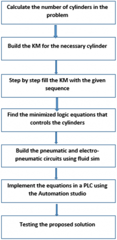
Figure 1. Block diagram of working procedure
The more complicated the circuit grows, especially as a result of a combinatorial explosion caused by a rise in the number of cylinders involved, the harder it is to find the control equations (sometimes necessitating the usage of auxiliary memory). It also requires the global market demands that production hours for the industrial sector get shorter and shorter. These issues could be resolved by utilizing the Karnaugh mapping method. The objective of this work is to develop multiple-actuator pneumatic circuits and reduce start-up times finding the set of optimized logic equations that allows any pneumatic circuit to be controlled electrically or pneumatically and merging various operational sequences into a single process.
To reduce starting delays, the suggested rules were used to simplify the logic equations and modify the Karnaugh Map for industry control of several-actuator pneumatic and electro pneumatic systems (PLC basis or Relay). as well as many movement sequences were also combined into a single order. Figure 1 displays the block diagram of the working process.
The pneumatic system refers to the air used to produce energy [11]. Cylinders and a set of directional control valves are used to regulate a typical pneumatic component. The general architecture of any given pneumatic actuation system, which is present in virtually all pneumatic devices, is made up of this collection of components, which is a combination of control, actuation, and location elements [10]. Other circuit components, such as logical elements (AND & OR), work to ensure that the signal group and compressed air flow to the cylinders occur in accordance with the specified logic at that specific moment. Because the pneumatic components are easy to install, maintain, have a long working life, and are simple in design, the pneumatic system was chosen for this project [12].
Traditionally, capital letters denote actuators, and lowercase letters denote actuator position at limit switches. In this case, the forward movement of the cylinder will be represented by the symbol A+, while the cylinder's backward movement will be represented by the symbol A [10]. Figure 2 shows a simplified representation of a pneumatic circuit.
Figure 2. A simplified representation of pneumatic circuit
The 'Karnaugh maps' method is typically used to minimize and simplify Boolean functions, or to convert a truth table into the associated logic circuit, allowing the least expression of a given logic function to be obtained systematically and expediently. This methodology, in a broader sense, solves problems in industrial automation. This technique may be used to create ON/OFF control systems that use electricity or compressed air as the command power. A Karnaugh map is a graphical representation of functions that systematically uses the algebraic simplification process [8]. In the latter case, the method also allows for circuit control through a programmable controller (PLC) [9]. The Karnough map is truly a crucial tool for processing algebraic logic that has minimal parameters. For a large number of variables, it can be said that working with a wide range of variables for the Karnaugh map will be a noteworthy accomplishment [13]. The construction map will be 2n cells in size, with "n" representing the number of cylinders (assuming each cylinder has just two end-of-stroke sensors) as well as additional memory if necessary [7]. Figure 3 shows the Karnaugh map for five variables.
Figure 3. Karnaugh maps for five variables (functions A, B, C, G, and E) without memory
The basic phases and methodical approach of the Karnaugh mapping methodology for pneumatic and electrical control circuit design are as follows [8]:
1. building the Karnaugh map
2. based on a set of rules, create a cycle path
3. Logic equations are minimized or optimized.
3.1 Rules for drawing cycle path
The rules that follow must be followed while drawing the cycling path on the Karnaugh map to guarantee that it is drawn correctly [14].
1. In the upper-left corner of the map, begin the plotting cycle.
2. In the cycle diagram, just take up one cell.
3. The map must be expanded to double the number of columns whenever a movement (A0, A1, B0, B1, C0, C1, etc.) takes place in a location that is already occupied.
Because the arrival house is occupied by order B+, the retreat order B– cannot be carried out, hence memory intervention is now required.
4. A memory can be moved by relocating to another vacant cell while maintaining all of the positions of the cylinder; this just alters the memory's state. This new movement was created by X1 if the memory is X (just changing x0 to x1). The cylinder movements must be prioritized before performing the memory reset.
5. The movement cycle should come to an end in the first home.
3.2 Logic equations optimization
The logic equation minimization, which is the methodology's heart, is the second and most important stage after generating the map. To accomplish so, some rules are applied to get the control equations for each of the cycle's cylinders, including the memory if necessary [9].
1. The number of cells chosen will always be a multiple of two (Power Rule) such as 20, 21, 22, 23.
2. Empty cells are jokers, in the sense that they can be selected at any time.
3. Any occupying cell that is between the cell containing the movement and the cell containing the opposing movement that we wish to regulate is prohibited. Let’s say we're looking for the equation for A0. All occupied cells in the route are prohibited between the cell holding A1 and the cell containing A0.
4. The logical equation for the subsequent motion must include the prior motion as an expression.
The machine consists of three stations (three Sequences) for filling and capping, corresponding to the S1, S2, and S3 pushbuttons as shown in Figure 4.
Figure 4. Filling and capping machine
Station 1(S1) is utilized for loading and transferring. To move the conveyor from one position to the right, transfer cylinder B is initially pushed out. Then, using cylinder A, a fresh empty bottle is loaded.
Station 2(S2) is where bottles are filled. The contents of the dosing container are emptied into the bottle by releasing cylinder C and opening valve D. Then, to refill the dosage container, valve D is shut and cylinder C is retracted.
Station 3(S3) is the capping station. A new cap is presented by the expansion of cylinder G and cylinder E is extended to compress the cap of the bottle. Finally, cylinders E and G must be retracted. Table 1 displays the push-button S1, S2, and S3 sequences.
Table 1. Movement sequence for S1, S2, S3
|
S1 |
S2 |
S3 |
|
$\mathrm{B}^{+}$ |
$\mathrm{B}^{+}$ |
$\mathrm{B}^{+}$ |
|
$\mathrm{B}^{-}$ |
$\mathrm{B}^{-}$ |
$\mathrm{B}^{-}$ |
|
$\mathrm{A}^{+}$ |
$\mathrm{C}^{+}$ |
$G^{+} E^{+}$ |
|
$\mathrm{A}^{-}$ |
$\mathrm{C}^{-}$ |
$G^{-} E^{-}$ |
An algebraic form, the more common form, or a displacement diagram are used to represent the motions of a sequence. the diagrams eliminate errors and make programming easier. The path-step diagram (PSD) shows how the pneumatic cylinder's piston rods are positioned for each step of the sequential command, whether they are extended or retracted [15]. the motions are displayed in a path step-diagram to make the movements more comprehensible. Figure 5 shows the displacement diagram of the S1, S2, and S3 sequences. The brown path shows the S1 sequence's movements. S2 is represented by the green step diagram, whereas S3 is represented by the red step diagram.
Figure 5. Displacement diagram of three sequences (S1, S2, and S3)
Construct the Karnaugh maps
Karnaugh's map is drawing for five-cylinder 25=32 cells,2map as shown in Figure 6, A memory (X) is needed to perform the necessary sequence since the arrival house is already occupied by the order B+, making it impossible to carry out the retreat order (B-). All sequences will begin their first movement at the map's upper left corner
Figure 6. Karnaugh Maps for filling and capping machine
According to the study [8], the map will expand horizontally or vertically depending on whether it is impossible to go (occupied target cell). The beginning cell of all moves is cell $a_0 b_0 c_0 g_0 e_0 \bar{x}$, therefore in this situation, the whole $\overline{\mathcal{x}}$ side of the map will be accountable for the B1 order.
Fill the KM with the supposed sequence one by one
Each address field in the KM must be filled out to indicate the necessary motions, and all sequences must start in the upper left corner of the map. Considering the connection between the states of the major variables (the distribution valves, represented by capital letters, memory in circuits that operate sequentially, and the end-of-stroke sensors (represented by lowercase letters), as seen in Figure 7.
Figure 7. Relationship between variables and orders
On the other hand, cell $a_0 b_0 c_0 g_0 e_0 x$ is the dividing cell of the S1, S2 and S3 sequences' movements, respectively (brown, green and red path) in Figure 6.
To create the equations, it is crucial to separate apart the sequences and each of the orders. Then, based on the analysis of the beginning movement's order, we can affirm that this that motion will always be performed regardless of the decision that is taken since it is the point at which all sequences begin. Since this is where all sequences begin, it must also be ensured that every movement is finished in the same cell. Therefore, the equation of motion corresponding to the B1 order must contain all active variables this case, the active variable for sequence S1 is a0 (previous movement), c0 for sequence S2 and e0g0 for sequence 3. As a result, the following equation will be used to govern the advance of cylinder B (order B1, see Figure 6):
$B_1=a_0 \bar{x} S_1+c_0 \bar{x} S_2+e_0 g_0 \bar{x} S_3$ (1)
The same method used for order B1 is used to get the other control equations. Thus, the order of S1 is as follows:
$B_0=x$ (2)
$A_1=b_0 x S_1$ (3)
$A_0=\bar{x}$ (4)
$X_1=b_1 S_1, X_0=a_1$ (5)
The map is also used to get the equations for the second sequence's (S2). B1 is solely reliant on S2 in this instance.
$B_1=C_0 \bar{x} S_2$ (6)
$B_0=x$ (7)
$C_1=b_0 x S_2$ (8)
$C_0=\bar{x}$ (9)
$X_1=b_1 S_2, X_0=c_1$ (10)
The equations for the S3 are likewise derived from the KM (Figure 6). B1 is solely reliant on S3 in this instance.
$B_1=e_0 g_0 \bar{x} S_3$ (11)
$B_0=x$ (12)
$G_1=E_1=b_0 x S_3$ (13)
$G_{0=} E_0=\bar{x}$ (14)
$X_1=b_1 S_3, X_0=g_1 e_1$ (15)
Using pneumatic 5/2 directional control valves, the merged sequences are controlled. (5 ways and 2 positions). The signals of each of the selected sequences will thus always be active as long as the sequence button, is pressed and as long as this kind of valve is in use (see "Start selector switches" and "Sequence selection," see Figure 8).
Figure 8. Memorized S1, S2, and S3 pneumatic signals
These three paths are used to form a set of equations that, based on if the S1, S2, or S3 button presses is selected, turns a set of sequences into a series of motions. The following will be the final set of equations:
$B_1=a_0 \bar{x} S_1+c_0 \bar{x} S_2+e_0 g_0 \bar{x} S_3$ (16)
$B_0=x$ (17)
$C_1=b_0 x S_2$ (18)
$C_0=\bar{x}$ (19)
$A_1=b_0 x S_1$ (20)
$A_0=\bar{x}$ (21)
$G_1=E_1=b_0 x S_3$ (22)
$G_0=E_0=\bar{x}$ (23)
$X_1=b_1\left(S_1+S_2+S_3\right), X_0=a_1+c_1+e_1 g_1$ (24)
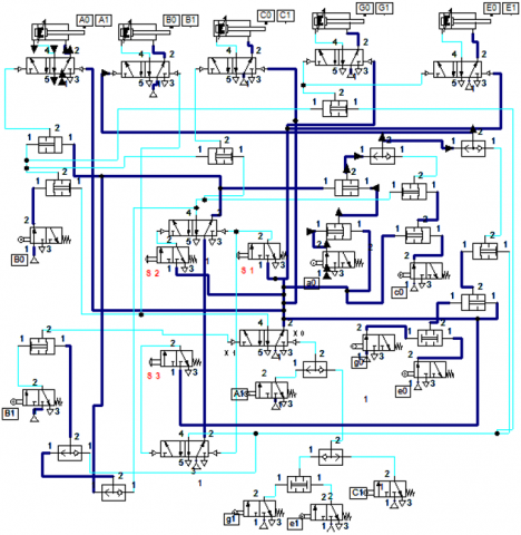
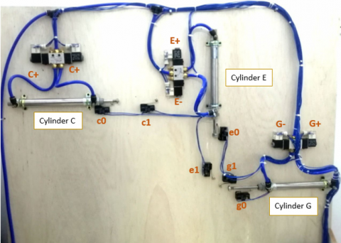
Finally, the final set of equations are then implemented using pneumatic components and simulated in accordance with the schematic given in Figure 9 and experimental work as indicated in Figure 10.
Figure 9. Pneumatic circuit of filling and capping
Figure 10. Experimental set up
A comprehensive piece of software called FluidSIM is used to design, simulate, teach, and research electro-pneumatic, electro-hydraulic, pneumatic, digital, and electronic circuits. The program's features all work together seamlessly, fusing various media and information sources in a way that is both accessible and flexible [16]. Students can use this simulation to test the validity of their theory. After being validated in a simulation, after being validated in a simulation, pneumatic and electrical schematics can be used in a real system.
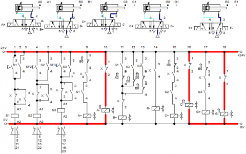
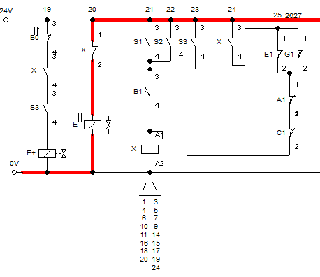
The electro-pneumatic circuit shown in Figure 11 was constructed using Fluid SimV4.2 simulation software to satisfy the reduced logic equations.
Figure 11. The simulation of the electro pneumatic control system implementation
Figure 12. Ladder implementation
It will be easy to build the electrical control of a pneumatic systems according to KM equations as all that is needed is to convert the equations into PLC ladder logic. The software was written in Ladder Logic using the Automation Studio simulation software (v7.0) As seen in Figure 12.
The cycle diagram may now be directly used to derive logical equations. Each command is represented on the map by a surface that can be quickly translated into a logical function (the address of the residence from which the command for movement was sent). As a result, the equations will be as follows:
$B_1=a_0 b_0 c_0 g_0 e_0 \bar{x} \overline{a_1} \overline{b_1} \overline{c_1} \ \overline{g_1}\ \overline{e_1}\left(S_1+S_2+S_3\right)$ (25)
$B_0=a_0 b_1 c_0 g_0 e_0 x \overline{a_1} \ \overline{b_0} \overline{c_1} \ \overline{g_1} \ \overline{e_1}$ (26)
$A_1=a_0 b_0 c_0 g_0 e_0 x \overline{a_1} \overline{b_1} \overline{c_1} \ \overline{g_1} \ \overline{e_1} S_1$ (27)
$A_0=a_1 b_0 c_0 g_0 e_0 \bar{x} \overline{a_0} \overline{b_1} \overline{c_1} \ \overline{g_1} \ \overline{e_1}$ (28)
$C_1=a_0 b_0 c_0 g_0 e_0 x \overline{a_1} \overline{b_1} \overline{c_1}\ \overline{g_1 }\ \overline{e_1} S_2$ (29)
$C_0=a_0 b_0 c_1 g_0 e_0 \bar{x} \overline{a_1} \overline{b_1} \overline{c_0}\ \overline{g_1}\ \overline{e_1}$ (30)
$G_1=E_1=a_0 b_0 c_0 g_0 e_0 x \overline{a_1} \overline{b_1} \overline{c_1}\ \overline{g_1} \ \overline{e_1} S_3$ (31)
$G_0=E_0=a_0 b_0 c_0 g_1 e_1 \bar{x} \overline{a_1} \overline{b_1} \ \overline{c_1} \ \overline{g_0}\ \overline{e_0}$ (32)
$X_1=a_0 b_1 c_0 g_0 e_0 \overline{a_1} \overline{b_0} \overline{c_1} \ \overline{g_1} \ \overline{e_1} \ \left(S_1+S_2+S_3\right)$ (33)
$\begin{aligned} & X_0=a_1 b_0 c_0 g_0 e_0 \overline{a_0} \overline{b_1} \overline{c_1} \ \overline{g_1} \ \overline{e_1} S_1 \quad+a_0 b_0 c_1 g_0 e_0 \overline{a_1} \overline{b_1} \overline{c_0} \ \overline{g_1} \ \overline{e_1} S_2 \quad+a_0 b_0 c_0 g_1 e_1 \overline{a_1} \overline{b_1} \overline{c_1} \ \overline{g_0} \ \overline{e_0} S_3\end{aligned}$ (34)
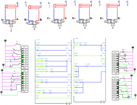
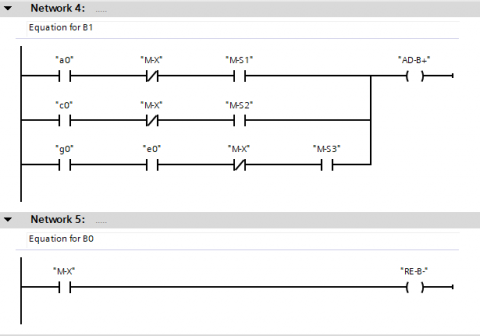
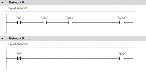
However, these equations are rather complicated for Programming in a PLC. They should be easier and more affordable to extract from the Karnaugh Map.SIMATIC TIA Portal V17 software, operating on a 1214C DC/DC/Rly CPU, was used to implement the control system. The tags for all digital inputs, outputs, and memory were placed in the first stage, as illustrated in Figure 13. The ladder diagram (main OB) was built to do the required actions for this project as explained as shown in Figure 14.
Figure 13. PLC tags
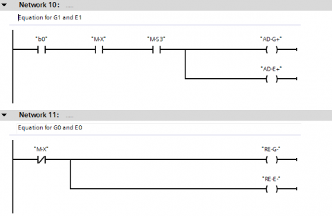
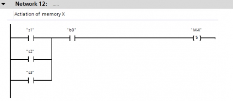
Figure 14. Implementation of ladder language
Control systems in industries require that a technician or process engineer have an accurate understanding of the problem and a working knowledge of the tools used in control systems or relay. Technicians who are near to the fabrication area or maintenance must program these devices. The electro-control may be carried out using Karnaugh procedures, which are typically well-known to maintenance personnel and can therefore readily be turned into LADDER language. The contribution of this work will be to increase the potential of using pneumatic control methodologies, extending its use not only in terms of industrial applications, maintenance or process engineering, and use of PLCs, but also the educational level, engineering schools, allowing a particular use in the automation of laboratories in the field of pneumatic control circuits and electro-pneumatic sequential control. In this paper, presented a technique that allows us to work with various sequence combinations from Karnaugh Map. in all the previously mentioned literature. A case study was presented, which discusses the implementation problems associated with manipulating Karnaugh maps in a two, three, four-cylinder configuration to minimize a logic equation. The difference is increasing the number of actuators (cylinders) where a case study was presented filling and capping machine, which involving a five-cylinder configuration to minimize a logic equation.
They were modified for pneumatic and electro-pneumatic industrial control (relay or PLC basis). This methodology provides for the solution of a high-complexity control issue as well as the potential of integrating many movement sequences into a single command. By applying the suggested rules, the logic equations were extracted in a simpler form, and they are simple to use pneumatically and electro pneumatically. It is also easily converted to the ladder Diagram language. The equations produced by KM guarantee the execution of predefined sequences (the triple route in our case) and a reduction of command variables, either applied to pneumatic systems or programmable logic controllers.
[1] Dakre, A., Sayed, J.G., Thorat, E.A., Chaudhary, A.A.M.A. (2015). Implementation of bottle filling and capping using PLC with SCADA. International Research Journal of Engineering and Technology, 2(2): 2588-2592.
[2] Khaleel, S.S., Salloom, M.Y., Mohammed, A.Z. (2020). Comparison sequences of pick and place system controlled using PLC. Al-Nahrain Journal for Engineering Sciences, 23(4): 397-407. https://doi.org/10.29194/NJES.23040397
[3] Hadi, H.H., Sallom, M.Y. (2019). Pneumatic control system of automatic production line using SCADA implement PLC. In 4th Scientific International Conference Najaf (SICN), Al-Najef, Iraq, 37-42. https://doi.org/10.1109/SICN47020.2019.9019356
[4] Al-Mesaody, A. (2017). Programming a pneumatic processes sequence based on plc by demonstration. Al-Khwarizmi Engineering Journal, 13(3): 46-54. https://doi.org/10.22153/kej.2017.04.001
[5] Aziz, E.H. (2020). Design simulation system to simplifying boolean equation by using Karnaugh Map. AL-Rafidain Journal of Computer Sciences and Mathematics, 14(1): 113-131. https://doi.org/10.33899/csmj.2020.164680
[6] Santos, A.A., da Silva, A.F. (2015). Electro pneumatic control versus grafcet. In Conference: International Congress on Education, Innovation and Learning Technologies At: Granada, Spain Volume, 1: 64-72.
[7] Da Silva, A.F., Santos, A.A. (2015). Teaching control pneumatic and electro-pneumatic circuits - a new method.
[8] Santos, A.A., Silva, A.F.D. (2017). Methodology for manipulation of Karnaugh maps designing for pneumatic sequential logic circuits. International Journal of Mechatronics and Automation, 6(1): 46-54. https://doi.org/10.1504/IJMA.2017.093307
[9] Da Silva, A.F., Santos, A.A. (2019). A simulation tool using AI technics and Karnaugh maps for learning and control digital pneumatics. In 2019 5th Experiment International Conference (exp. at'19), Funchal, Portugal, pp. 434-438. https://doi.org/10.1109/EXPAT.2019.8876488
[10] Santos, A.A., Da Silva, A.F. (2021). Adaptability of Karnaugh Maps to implement and solve complex control problems of pneumatic and electropneumatic systems. Global Journals of Research in Engineering, 21(A2): 39-49.
[11] Parnichkun, M., Ngaecharoenkul, C. (2001). Kinematics control of a pneumatic system by hybrid fuzzy PID. Mechatronics, 11(8): 1001-1023. https://doi.org/10.1016/S0957-4158(00)00040-4
[12] Hadi, H.H., Salloom, M.Y. (2019). Pneumatic control system of automatic production line using two method of SCADA/HMI implement PLC. Al-Khwarizmi Engineering Journal, 15(3): 16-28. https://doi.org/10.22153/kej.2019.06.006
[13] Islam, M.J., Hussain, M.G., Sultana, B., Rahman, M., Rahman, M.S., Rahaman, M.A. (2020). Simplifying the Boolean equation based on simulation system using Karnaugh mapping tool in digital circuit design. GUB Journal of Science and Engineering (GUBJSE), 7(1): 76-84.
[14] Sim, S.K., Chua, P.S. (1996). Symbolic pattern manipulation of Karnaugh-Veitch maps for pneumatic circuits. Artificial Intelligence in Engineering, 10(1): 71-83. https://doi.org/10.1016/0954-1810(95)00017-8
[15] Valdiero, A.C., Mantovani Jr, I., Fiegenbaum, A., Dambroz, G.P., Rasia, L.A. (2016). Development of a pneumatically driven cell for low cost automation. Journal of Industrial Engineering, 2016: 8431893. http://dx.doi.org/10.1155/2016/8431893
[16] Vujičić, V., Dragićević, S., Ocokoljić, D., Milićević, I., Popović, M. (2020). Design and simulation of electro-pneumatic motion control system. In 8th International Scientific Conference Technics and Informatics in Education, pp. 354-358.