Goh Ming Qian![]() | Mohd Riduwan Bin Ghazali*
| Mohd Riduwan Bin Ghazali*![]() | Mohd Ashraf Bin Ahmad
| Mohd Ashraf Bin Ahmad![]() | Muhamad Shahir Bin Mohd Shukri
| Muhamad Shahir Bin Mohd Shukri
© 2023 IIETA. This article is published by IIETA and is licensed under the CC BY 4.0 license (http://creativecommons.org/licenses/by/4.0/).
OPEN ACCESS
This paper presents a data driven Sigmoid Proportional-Integral-Derivation (SPID) controller for a Twin Rotor Multiple-Input-Multiple-Output (MIMO) System (TRMS). A time-varying PID parameters based on sigmoid function is adopted to solve the low control accuracy of the conventional PID controller. In particular, the parameters of new version controller were vigorously changed based on its error signal of sigmoid function where its variability is limited in a predefined upper and lower bound. These SPID parameters are then optimized by using Adaptive Safe Experimentation Dynamics (ASED) method such that the control performance accuracy in terms of trajectory tracking error and control input energy are minimized. The simulations of step response analysis and stability analysis are conducted to evaluate the effectiveness of the proposed SPID controller compared to PID controller on TRMS system. Consequently, the results obtained from the simulations revealed that the SPID controller has successfully produced improvement in terms of objective function, J, total norm of error, $\bar{e}_1+\bar{e}_2$ and total norm of output, $\bar{u}_h+\bar{u}_v$ by reduced 6.84%, 6.38% and 4.25%, respectively compared to the PID controller. In addition, the results of Integral-Absolute-Error (IAE), Integral-Square-Error (ISE), Integral- Time-Absolute-Error (ITAE) and Integral-Square-Error (ITSE) are proven that the SPID controller is outperform on horizontal and vertical planes for TRMS system in comparison with PID controller.
ASED method, data driven, sigmoid PID controller, TRMS system
In recent years, the application of helicopter has employed to many fields such as military, surveillance, transportation, rescue operation [1] and architectural photogrammetry [2]. In order to improve the control performance of helicopter, researchers design a prototype of laboratory helicopter for experiment. The platform is called Twin Rotor Multiple-Input-Multiple-Output System (TRMS) because of its behaviour is similar to helicopters. Furthermore, TRMS is usually investigated as a system of nonlinear MIMO by researchers. The TRMS consists of two angular Degree of Freedom (DOF) are yaw angle and pitch angle. In addition, the changing of the voltage input of the main motor can modify pitch angle to operate the main propeller’s rotation speed. Meanwhile, the angle of yaw can be modified by the changing of the voltage input of the tail motor to operate the tail propeller’s rotation speed. It is not trivial to construct an effective controller for the TRMS to reach the desirable pitch and yaw angles due to the mutual interference between two propellers.
Furthermore, the nonlinear system of TRMS whose dynamical models are difficult to derive and implement. This is because the model has complicated higher order polynomial or differential equations are required to fully characterized the controller plant [3]. Eventually, many researchers motivate intensively to the TRMS system development based on closed-loop control structure in the attempt to resolve the complexity of structure for TRMS.
In a few decades ago, many researchers proposed the different types of control techniques to control the performance of TRMS on horizontal and vertical planes. For instance, the proposed control techniques that applied in TRMS system such as Proportional-Integral-Derivative (PID) controller [4-9], Linear Quadratic Regulator (LQR) [10], Sigmoid-PID (SPID) controller [11], Fractional-order PID (FOPID) controller [12-17], Fuzzy Logic controller [18], Sliding Mode Controller (SMC) [19-21], Fuzzy-PID (FPID) controller [22-26] and Model Predictive Controller (MPC) [27].
Nevertheless, researchers and scientific community put the greatest attention in the combinations of different type control technique based PID controller. Many literature sources have reported that the variable structure PID (VS-PID) can enhance that performance of the traditional PID controller [28-30]. Hence, it is worth mentioning that a sigmoid function, which belongs to the VS family was presented in reference [11]. The sigmoid function is a nonlinear which means that it can capture complex relationship between input and output variables. Additionally, it is also bounded between 0 and 1 which makes it ideal for modeling probabilities or other quantities that are constrained to lie within this range. For this purpose, modified version of the sigmoid function that used by researchers perturb each PID coefficient in a preset range based on the amount of the error signal. Hence, the modified sigmoid function compresses PID controller coefficients between the boundaries of upper and lower nonlinearly. The SPID controller offers great potential to produce a smooth and continuous output which helps to avoid overshooting and oscillations in the system response, this can lead to better overall stability and faster settling times. Besides, SPID controller is often more robust to changes in the system parameters such as changes in the gain or time constant. This is because the modified sigmoid function has a built-in saturation limit that prevents the controller output from becoming large too large or too small [31, 32].
Consequently, SPID controller is also becoming more interest of researchers because of it can improve the flexibility of design in various engineering field such as system of TRMS. However, according to the literatures, SPID controller lacks knowledge to implement on TRMS and it must be pre-fixed parameters to tune before the SPID controller apply fully its capabilities in the system of TRMS. Thus, it is become a challenging in tuning of SPID controller due to SPID controller contains more parameters than the typical PID controller. In order to acquire the optimal parameters of SPID controller, therefore, it is crucial to choose an appropriate optimization method.
On the other hand, Adaptive Safe Experimentation Dynamics (ASED) method is one of the good optimization method candidates that can be used to tune the SPID controller. Besides, ASED as a single agent technique for achieving optimum design parameters has been highlighted for its ability to provide consistent convergence while achieving improved control precision by preserving the best optimal values when the parameters are changed. Furthermore, ASED method adjust to the system’s goal function to prevent premature convergence during design parameter update. This circumstance has the potential to improve the accuracy performance using an updated mechanism that is adaptive to the change of the objective function [29]. Thus, this study is motivated to adopt the ASED method to apply in the implementation of data-driven SPID controller on TRMS system.
In overall of this paper, a novel data driven Sigmoid PID controller based on Adaptive Safe Experimentation Dynamic method is proposed. In addition, the ASED method is used to optimize the control parameters which are Kp, Ki, Kd and α in the SPID controller. Then, the SPID-ASED controller is applied in a system of TRMS to provide optimum control accuracy. Eventually, several study cases are conducted to investigate and compare the performance of the proposed SPID-ASED controller with the controller of PID-ASED. Firstly, step response analysis is performed to investigate the optimum SPID control performance based on ASED method. In addition, the control performance is evaluated in terms of objective function, total norm error and total norm output. Besides, the performance of controller in terms of rise time (Tr), settling time (Ts), overshoot (OS), steady-state error (ess) are discussed. Lastly, the evaluation of robustness of controllers in terms of Integral-Absolute-Error (IAE), Integral-Square-Error (ISE), Integral-Time-Absolute-Error (ITAE) and Integral-Time-Square-Error (ITSE) are examined.
The outline of this paper is performed as follows. The system description of TRMS is showed in Section 2. In Section 3, the problem of data-driven Sigmoid PID in minimizing the performance index or norm error of horizontal and vertical axes on the platform of TRMS is formulated. In Section 4, the methodology of ASED-based algorithm, which is operated for sigmoid PID tuning, is summarized. The proposed controller is then validated to a given TRMS model in Section 5. The analysis and performances comparison between the proposed controller and other existing control methods are also demonstrated. Finally, the conclusion of this paper is summarized in Section 6.
Notation: The set of real numbers is represented by the symbol, $\mathbb{R}$ and the set of positive real numbers is represented to the symbol, $\mathbb{R}_{+}$. The set of n real numbers is represented by the symbol, $\mathbb{R}^n$. The vector in which all elements are zero and one to define 0 and 1, respectively.
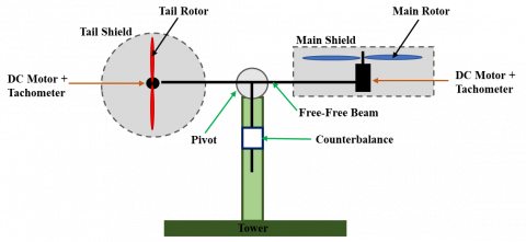
In this section, the explanation for the Twin Rotor Multiple-Input-Multiple-Output System (TRMS) is firstly provided. TRMS is an electromechanical laboratory equipment that serve as a paradigm in the research of aircraft such as helicopters, airplanes and spacecraft which is constructed by Feedback Instrument Limited [33]. Figure 1 shows the system of TRMS considered in this experiment. In system of TRMS, the main and tail propellers driven by independent main and tail DC motors, respectively on the beam which perpendicular to each other. Moreover, the beam pivoted on its base that can rotate freely in both planes of horizontal and vertical. The counterweights with a counterbalance at their ends are attached to the beam base.
Figure 1. The Aero-dynamical model of the TRMS system [34]
According to paper [34], the voltage control inputs of the main and tail DC motors are represented by the symbol, uh and uv, respectively. By taking the derivative of ih and iv, it can be presented in the following equations:
$\dot{i_h}=\frac{1}{T_{t r}}\left(u_h-i_h\right)$ (1)
and
$\dot{i_v}=\frac{1}{T_{m r}}\left(u_v-i_v\right)$ (2)
respectively. ih and iv are armature current of horizontal and vertical DC motor, respectively. The time constant of tail rotor and main rotor are denoted as Ttr and Tmr. Moreover, the tail propeller’s angular velocity, ωt is a nonlinear function of the horizontal armature current, ih is given as:
$\begin{aligned} & \omega_t\left(i_h\right)=2020 i_h^5-194.69 i_h^4-4283.15 i_h^3+262.27 i_h^2+3768.83 i_h\end{aligned}$ (3)
Meanwhile, the angular velocity of main propeller, ωm is a nonlinear function of the vertical armature current, iv can be obtained as follows:
$\begin{aligned} \omega_m\left(i_v\right) & =90.99 i_v^6+599.73 i_v^5-129.26 i_v^4 -1283.64 i_v^3+63.45 i_v^2+1283.41 i_v\end{aligned}$ (4)
Furthermore, with being Eq. (3) and Eq. (4), it can approximately illustrate the propulsive force moving the joined beam in direction of horizontal and vertical, respectively. The propulsive forces of TRMS in horizontal direction, Fh and in vertical direction, Fv are, therefore, interpreted as follows:
$\begin{aligned} & F_h\left(\omega_t\right)=-3 \times 10^{-14} \omega_t^5-1.595 \times 10^{-11} \omega_t^4 +2.511 \times 10^{-7} \omega_t^3 -1.808 \times 10^{-4} \omega_t^2+8.01 \times 10^{-2} \omega_t\end{aligned}$ (5)
and
$\begin{aligned} F_v\left(\omega_m\right)=-3.48 & \times 10^{-12} \omega_m^5+1.09 \times 10^{-9} \omega_m^4 +4.123 \times 10^{-6} \omega_m^3 -1.632 \times 10^{-4} \omega_m^2+9.544 \times 10^{-2} \omega_m\end{aligned}$ (6)
Eventually, the dynamic equations of TRMS are included the derivative of ih and iV, therefore, formulated by:
$\dot{s_h}=l_t S_f F_h\left(\omega_t\right) \cos \alpha_v-k_h \Omega_h$, (7)
$\begin{gathered}\dot{s}_v=l_m S_f F_v\left(\omega_m\right)-g\left(0.0099 \cos \alpha_v+\right. \left.0.0168 \sin \alpha_v\right)-k_v \Omega_v-0.0252 \Omega_h^2 \sin 2 \alpha_v\end{gathered}$, (8)
$\dot{i_h}=\frac{1}{T_{t r}}\left(u_h-i_h\right)$, (9)
$\dot{i_v}=\frac{1}{T_{m x}}\left(u_v-i_v\right)$ (10)
where,
$\Omega_h=\dot{\alpha}_h=\frac{s_h+J m r \omega_m\left(i_v\right) \cos \alpha_v}{D \sin ^2 \alpha_v+E \cos ^2 \alpha_v+G}$, (11)
$\Omega_v=\dot{\alpha}_v=9.1\left(s_v+J_{t r} \omega_t\left(i_h\right)\right)$ (12)
The symbols of $\dot{s_h}$ and $\dot{s_v}$ denote the angular momentum in horizontal and vertical planes under differential function, respectively. The yaw angular velocity in horizontal plane is represented by Ωh whereas the pitch angular velocity in vertical plane is represented by Ωv. Additionally, the equations of Ωh and Ωv also can be obtained by taking derivative of yaw angle, αh and pitch angle, αv, respectively. Besides, it should be noted that the angular velocities of Ωh and Ωv are different compared to the angular velocities of ωt and ωm. The terms of cos and sin are the notations of cosine and sine function, respectively. Lastly, the detailed parameters of TRMS are also fully summarized in Table 1.
Moreover, the block diagram to indicate the relationship between the voltage control inputs and its angles on horizontal and vertical planes is presented in Figure 2. The output evaluations in this research that generated by TRMS which are yaw angle, αh and pitch angle, αv is according to its control inputs which are uh and uv, respectively. Noted that, the mathematical equations of TRMS are according to information above.
Figure 2. The block diagram of the relationship between voltage control inputs and its angles [35]
Table 1. The detailed parameters of TRMS
|
Symbol |
Definition |
Value |
|
lm |
main part length of the beam |
0.236 m |
|
lt |
tail part length of the beam |
0.250 m |
|
kv |
the friction coefficient for the vertical axis |
0.095 |
|
kh |
the friction coefficient for the horizontal axis |
0.0054 |
|
Jmr |
moment of inertia in the DC motor of main propeller |
1.6543×10⁻⁵ kgm2 |
|
Jtr |
moment of inertia in the DC motor of tail propeller |
2.6500×10⁻⁵ kgm2 |
|
Tmr |
time constant of the main rotor |
1.4320 s |
|
Ttr |
time constant of the tail rotor |
0.3842 s |
|
D |
mechanical related constant |
1.60650×10⁻³ kgm2 |
|
E |
mechanical related constant |
4.90092×10⁻² kgm2 |
|
G |
mechanical related constant |
6.33060×10⁻³ kgm2 |
|
Sf |
balanced scale |
8.43318×10⁻⁴ |
|
g |
gravitational acceleration |
9.81 ms-2 |
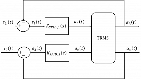
The block diagram of SPID controller on TRMS plant is illustrated in Figure 3. Here, considers two of the proposed SPID controllers, $K_{S P I D_1}$ and $K_{S P I D_2}$ are implemented into MIMO plant of TRMS to control its horizontal and vertical planes, respectively. The references toward the set point are represented as r1(t) and r2(t) for horizontal and vertical planes, respectively. Besides, e1(t) and e2(t) is the error between the reference and the output measurements on the horizontal and vertical planes, respectively.
Figure 3. The block diagram of SPID controller for a plant of TRMS
Next, the general sigmoid function is a continuous variant of the function of ramp which is known as the sigmoidal curve or logistic function. It is mainly used to limit the output of system. Therefore, the general function of Sigmoid is shown in following equation:
$f(x)=\frac{1}{1+e^{-\alpha x}}$ (13)
The term of α is the transition coefficient that is used to adjust sharpness of transition between the bounds of lower and upper. Based on Figure 3, the function of Sigmoid in SPID controller is used to adjust the coefficients of PID and Eq. (13) is modified, therefore, presented as follows:
$f(x)=x_{l o w}+\left|\frac{x_{\text {high }}-x_{l o w}}{1+e^{-\alpha|e(t)|}}\right|$ (14)
Hence, the transfer function of proposed SPID controllers on horizontal and vertical planes for TRMS in this research can be derived as:
$K_{S P I D_1}(s)=\widetilde{K_{p_1}}+\frac{\widetilde{K_{i_1}}}{s}+\widetilde{K_{d_1}} s$ (15)
and
$K_{S P I D_2}(s)=\widetilde{K_{p_2}}+\frac{\widetilde{K_{i_2}}}{s}+\widetilde{K_{d_2}} s$ (16)
where,
$\widetilde{K_{p_1}}=K_{p_{1 l o w}}+\left|\frac{\Delta_{K p_1}}{1+e^{-\alpha p_1|e(t)|}}\right|$ (17)
$\widetilde{K_{l_1}}=K_{i_{1 l o w}}+\left|\frac{\Delta_{K_{i_1}}}{1+e^{-\alpha_{i_1}|e(t)|}}\right|$, (18)
$\widetilde{K_{d_1}}=K_{d_{1 \text { low }}}+\left|\frac{\Delta_{K_{d_1}}}{1+e^{-\alpha_{d_1}|e(t)|}}\right|$, (19)
$\widetilde{K_{p_2}}=K_{p_{2 l o w}}+\left|\frac{\Delta_{K p_2}}{1+e^{-\alpha p_2|e(t)|}}\right|$ (20)
$\widetilde{K_{p_2}}=K_{p_{2 l o w}}+\left|\frac{\Delta_{K p_2}}{1+e^{-\alpha p_2|e(t)|}}\right|$, (20)
$\widetilde{K_{l_2}}=K_{i_{2 l o w}}+\left|\frac{\Delta_{K_{i_2}}}{1+e^{-\alpha_{i_2}|e(t)|}}\right|$, (21)
and
$\widetilde{K_{d_2}}=K_{d_{2 l o w}}+\left|\frac{{ }^{K_{d_2}}}{1+e^{-\alpha_{d_2}|e(t)|}}\right|$. (22)
such that $\Delta_{K_{p_1}}=\left|K_{p_{1 \text { high }}}-K_{p_{1 \text { low}}}\,\right|, \Delta_{K_{i_1}}=\left|K_{i_{1 \text { high }}}-K_{i_{1 \text { low }}}\,\right|$, $\Delta_{K_{d_1}}=\left|K_{d_{1 \text { high }}}-K_{d_{1 \text { low }}}\,\right|, \Delta_{K_{p_2}}=\left|K_{p_{2 \text { high }}}-K_{p_{2 \text { low }}}\,\right|, \Delta_{K_{i_2}}=$ $\left|K_{i_{2 \text { high }}}-K_{i_{2 \text { low }}}\,\right|$ and $\Delta_{K_{d_2}}=\left|K_{d_{2 h i g h}}-K_{d_{2 l o w}}\,\right|$ are the difference in respective of $K_{p_1}, K_{i_1}, K_{d_1}, K_{p_2}, K_{i_2}$ and $K_{d_2}$ for the simplicity of design parameters tuning. Moreover, $K_{p_{\text {1low }}} \in \mathbb{R}, K_{i_{\text {1low }}} \in \mathbb{R}, K_{d_{\text {1low }}} \in \mathbb{R}, K_{p_{\text {2low }}} \in \mathbb{R}, K_{i_{\text {llow }}} \in \mathbb{R}$, and $K_{d_{2 l o w}} \in \mathbb{R}$ are lower bounds of $K_{p_1}, K_{i_1}, K_{d_1}, K_{p_2}, K_{i_2}$ and $K_{d_2}$, respectively. Meanwhile, $K_{p_{1 \text { high }}} \in \mathbb{R}, K_{i_{1 \text { high }}} \in \mathbb{R}$, $K_{d_{1 \text { high }}} \in \mathbb{R}, K_{p_{2 h i g h}} \in \mathbb{R}, K_{i_{2 h i g h}} \in \mathbb{R}$, and $K_{d_{2 h i g h}} \in \mathbb{R}$ are upper bounds of $K_{p_1}, K_{i_1}, K_{d_1}, K_{p_2}, K_{i_2}$ and $K_{d_2}$, respectively. In addition, the coefficient to adjust the curve sharpness between lower and upper bounds of $\widetilde{K_{p_1}}, \widetilde{K_{l_1}}, \widetilde{K_{d_1}}, \widetilde{K_{p_2}}, \widetilde{K_{l_2}}$ and $\widetilde{K_{d_2}}$ are denoted as $\alpha_{p_1} \in \mathbb{R}, \alpha_{i_1} \in \mathbb{R}, \alpha_{d_1} \in \mathbb{R}, \alpha_{p_2} \in \mathbb{R}$, $\alpha_{i_2} \in \mathbb{R}$ and $\alpha_{d_2} \in \mathbb{R}$, respectively. Note that $\widetilde{K_{p_1}}, \widetilde{K_{l_1}}, \widetilde{K_{d_1}}$, $\widetilde{K_{p_2}}, \widetilde{K_{l_2}}$ and $\widetilde{K_{d_2}}$ values are based on the error signals, $e_1(t)$ and $e_2(t)$ to be changed by using constant gains of proportional, integral and derivative in PID controller immediately.
Remark 3.1 This paper presented the proposed SPID controller is different compared to paper [11] in several ways. Firstly, considers two of the proposed SPID controllers to implement into TRMS for each of horizontal and vertical planes. Lastly, for each for each $\widetilde{K_{p_1}}, \widetilde{K_{l_1}}, \widetilde{K_{d_1}}, \widetilde{K_{p_2}}, \widetilde{K_{l_2}}$ and $\widetilde{K_{d_2}}$, consider a unique value of the curve sharpness such that $\alpha_{p_1}, \alpha_{i_1}, \alpha_{d_1}, \alpha_{p_2}, \alpha_{i_2}$ and $\alpha_{d_2}$, respectively. This change is anticipated to increase the flexibility and variety of SPID controller.
Furthermore, the following equations are subsequently be used to evaluate the system’s performance:
$\bar{e}_1=\int_{t_o}^{t_f}\left(r_1(t)-\alpha_h(t)\right)^2$, (23)
$\bar{e}_2=\int_{t_0}^{t_f}\left(r_2(t)-\alpha_v(t)\right)^2$, (24)
$\bar{u}_h=\int_{t_n}^{t_f}\left(u_h(t)\right)^2$ (25)
and
$\bar{u}_v=\int_{t_0}^{t_f}\left(u_v(t)\right)^2$ (26)
such that the control performance assessment duration is represented the interval [to, tf], where $t_o \in 0 \cup \mathbb{R}_{+}$and $t_f \in \mathbb{R}_{+}$. Consequently, the objective function of SPID control system is given as:
$\begin{aligned} & J\left(\boldsymbol{K}_{\text {plow }}, \boldsymbol{K}_{\text {ilow }}, \boldsymbol{K}_{\text {dlow }}, \Delta_{\boldsymbol{K}_p}, \Delta_{K_{i_i}}, \Delta_{\boldsymbol{K}_d}, \boldsymbol{\alpha}_{\boldsymbol{K}_{p^{\prime}}}, \boldsymbol{\alpha}_{\boldsymbol{K}_i}, \boldsymbol{\alpha}_{\boldsymbol{K}_d}\right) \quad=w_1 \bar{e}_1+w_2 \bar{e}_2+w_3 \bar{u}_v+w_4 \bar{u}_h\end{aligned}$ (27)
From $\quad$ Eq. $\quad(27), \quad \boldsymbol{K}_{\text {plow }}=\left[K_{p_{1 \text { low }}}, K_{p_{2 l o w}}\,\right]$, $\boldsymbol{K}_{\boldsymbol{i}}=\left[K_{i_{1 \text { low }}}, K_{i_{2 \text { low }}}\,\right], \quad \boldsymbol{K}_{\boldsymbol{d}}=\left[K_{d_{1 \text { low }}}, K_{d_{2 \text { low }}}\,\right]$, $\Delta_{K_p}=\left[\Delta_{K_{p_1}}, \Delta_{K_{p_2}}\right]$, $\Delta_{K_i}=\left[\Delta_{K_{i_1}}, \Delta_{K_{i_2}}\right]$, $\Delta_{K_d}=\left[\Delta_{K_{d_1}}, \Delta_{K_{d_2}}\right]$, $\boldsymbol{\alpha}_{\boldsymbol{K}_p}=\left\lfloor\alpha_{K_{p_1}}, \alpha_{K_{p_2}}\right]$, $\boldsymbol{\alpha}_{\boldsymbol{K}_{\boldsymbol{i}}}=\left[\alpha_{K_{i_1}}, \alpha_{K_{i_2}}\right]$, $\boldsymbol{\alpha}_{K_{\boldsymbol{d}}}=\left[\alpha_{K_{d_1}}, \alpha_{K_{d_2}}\right]$. Moreover, the outputs of weighting factor are denoted by symbols of $w_1$ and $w_2$ whereas $w_3$ and $w_4$ denote as the inputs of weighting factor. Noted that these weighting factors value are decided by the researcher. Then, the tracking error and control inputs are corresponded with fours term in the right hand-side of Eq. (27).
Problem 3.1 Provide the system of TRMS in Figure 3 by given the inputs data are uh and uv whereas the outputs data are αh and αv, design a SPID controller that minimize the objective function, J(ψ) with regard to ψ.
The key method to the solution of Problem 3.1 is presented in this section. Firstly, the control strategy of ASED algorithm is explained in sub-section 4.1. Then, the employment of data driven SPID controller based on algorithm of ASED for minimizing the control objective as shown in Eq. (27) is described in sub-section 4.2.
4.1 ASED method
ASED is a game theoretic method that randomly perturbs several elements of its design parameter to search for the optimal design parameter. The problem of general optimization by minimizing the objective function, f(τ) is highlighted as follows:
$\min _{\tau \in \mathbb{R}^n} f(\tau)$ (28)
where, the design parameter is denoted as $\tau \in \mathbb{R}^n$.
Furthermore, in seek of the optimal solution, τ, ASED algorithm [34] is applied through updating the design parameter procedure. Therefore, the algorithm of ASED updated law is expressed by:
$\begin{gathered}\tau_i(k+1)= \begin{cases}h\left(\overline{\tau_l}-K_g r v_2\right)+K_{g 1}\left(\frac{f(\tau(k))-\bar{f}}{f(\tau(k))}\right) & \text { if } r v_1 \leq E T, \\ \overline{\tau_l}+K_{g 1}\left(\frac{f(\tau(k))-\bar{f}}{f(\tau(k))}\right) & \text { if } r v_1 \geq E T,\end{cases} \end{gathered}$ (29)
where, k=1, 2, ⋯, kmax is the number of iterations, $\tau_i \in \mathbb{R}$ represents the ith element of $\boldsymbol{\tau} \in \mathbb{R}^n, \bar{\tau}_l \in \mathbb{R}$ represents the $i^{t h}$ element of $\overline{\boldsymbol{\tau}} \in \mathbb{R}^n$ and $\overline{\boldsymbol{\tau}}$ is for storing the current best value of the design parameters. The symbol Kg denotes a scalar that defines the interval size on the random steps in $\tau_i \in \mathbb{R} . K_{g 1}$ and ET denote the adaptive coefficient and a value of probability of new arbitrary for τ, respectively. $f(\boldsymbol{\tau}(k)) \in R_{+}$ is the current objective function, meanwhile $\bar{f}$ is the current best value of the objective function. Note that, $r v_1 \in \mathbb{R}$ is a random number that has been uniformly selected between 0 and 1.
Based on Eq. (29), the function of $h\left(\overline{\tau_i}-K_g r v_2\right)$ is defined as follows:
$h(\cdot)=\left\{\begin{aligned} \tau_{\max }, & \text { if } \bar{\tau}_l-K_g r v_2<\tau_{\max }, \\ \bar{\tau}_l-K_g r v_2, & \text { if } \tau_{\min } \leq \bar{\tau}_l-K_g r v_2 \leq \tau_{\max }, \\ \tau_{\min }, & \text { if } \bar{\tau}_l-K_g r v_2<\tau_{\min },\end{aligned}\right.$ (30)
where, τmin and τmax represent the value of design parameter in the lower boundary and upper boundary, respectively. Note that, $r v_2 \in \mathbb{R}$ is the new random number that has been uniformly selected between the τmin and τmax. Moreover, the procedures of the ASED algorithm are given in Figure 4.
4.2 Design of data driven SPID controller
This sub-section presents the parameters of SPID controller are tuned based on the algorithm of ASED for MIMO system. In order to accelerate the exploration of the design parameter searching, a logarithmic scale is employed for the design parameter, τ. Hence, the Sigmoid-PID parameters are stated in following equation:
$\psi=J \in R^{18}$ (31)
where, each element of ψ is given by $\psi_i=10^{\tau_i}(i=1,2, \ldots, 18)$. Therefore, the objective function is being written as $f(\boldsymbol{\tau})=\left[10^{\tau_1}, 10^{\tau_2}, \ldots, 10^{\tau_{18}}\right]^{\mathrm{T}}$. Following with this, the procedure of Sigmoid-PID controller tuned based on the algorithm of ASED is explained as below:
Step 1: Set the maximum iteration, kmax. In the initial stage, the each of design parameter is considered as τi=logψi and objective function, f(τ)=J(ψ).
Step 2: The algorithm of ASED is executed in Eq. (31) to obtain the optimal design parameters.
Step 3: The maximum iteration, kmax and the optimal design parameters, $\boldsymbol{\tau}_{o p t}=\overline{\boldsymbol{\tau}}\left(k_{\max }\right)$ are subsequently obtained. Then, the controller of Sigmoid-PID is executed by applying with $\boldsymbol{\psi}_{\text {opt }}=\left[\begin{array}{llll}10^{\tau_{1 o p t}} & 10^{\tau_{2 o p t}} \ldots 10^{\tau_{18 o p t}}\end{array}\right]$ in Figure 3.
Figure 4. The flow chart of ASED algorithm’s updated procedure
In this section, the simulation experiment results present the implementation of data-driven proposed SPID controller for TRMS which was analyzed by using MATLAB Simulink. The investigation of comparison results between the proposed SPID controller and PID controller that tuned through the algorithm ASED is considered two study cases which are step response and stability performance. These study cases are discussed in sub-section 5.1 and sub-section 5.2, respectively. Besides, the performance analysis of controllers is investigated in terms of objective function, J, total norm of error, $\bar{e}_1+\bar{e}_2$ and total norm of output, $\bar{u}_h+\bar{u}_v$. Therefore, the coefficients in ASED algorithm are defined as Kg=0.022, Kg1=0.0008, ET=0.66, τmin=-15 and τmax=15. In addition, the coefficient of weights is also established as $w_1=1000, w_2=1200, w_3=1$ and $w_4=1$. Note that these coefficients values in ASED algorithm are defined by running several trials and the coefficients that obtain the best results are selected [36]. Furthermore, the desired signals simulation of r1 and r2 are set at 0.5 m and -0.5 m, respectively from the initial time, to=0 s until the final time, tf=200 s. In this simulation experiment, the maximum of total number of iterations is given as kmax=3500.
5.1 Step response analysis
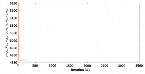
In this section, the analysis of step response is discussed. The best objective function, J convergence curve response with 3000 iterations is illustrated in Figure 5. As observed, the objective function of proposed SPID controller has successfully converged from J(ψ)=5247.40 and achieved the minimum J(ψ)=4861.50 during simulate with iteration, k=3500. It is proven that the effectiveness of ASED algorithm in minimizing the objective function of proposed SPID controller throughout the simulation timeframe at a constant convergence rate.
Figure 5. The result of objective function, J of SPID controller for TRMS system
Table 2. The parameters of SPID for TRMS system
|
Ψ |
SPID |
τ(0) |
10τ(0) |
τopt |
$10^{\tau_{\text {opt }}}$ |
|
ψ1 |
$K_{p_{\text {1low }}}$ |
-1 |
0.1 |
-0.8798 |
0.1319 |
|
ψ2 |
$\Delta_{K_{p_1}}$ |
-3 |
1.0×10⁻³ |
-2.8798 |
1.3189×10⁻³ |
|
ψ3 |
$\alpha_{p_1}$ |
0 |
1.0 |
0.1202 |
1.3189 |
|
ψ4 |
$K_{i_{\text {1low }}}$ |
-6 |
1.0×10⁻⁶ |
-5.8798 |
1.3189×10⁻⁶ |
|
ψ5 |
$\Delta_{K_{i_1}}$ |
-9 |
1.0×10⁻⁹ |
-6.9936 |
1.0148×10⁻⁷ |
|
ψ6 |
$\alpha_{i_1}$ |
0 |
1.0 |
0.1202 |
1.3189 |
|
ψ7 |
$K_{d_{\text {1low }}}$ |
-1 |
0.1 |
-0.8798 |
0.1319 |
|
ψ8 |
$\Delta_{K_{d_1}}$ |
-1 |
0.1 |
-0.8798 |
0.1319 |
|
ψ9 |
$\alpha_{d_1}$ |
0 |
1.0 |
0.1202 |
1.3189 |
|
ψ10 |
$K_{p_{\text {2low }}}$ |
-0.6989 |
0.2 |
-0.5788 |
0.2638 |
|
ψ11 |
$\Delta_{K_{p_2}}$ |
0 |
1.0 |
0.1202 |
1.3189 |
|
ψ12 |
$\alpha_{p_2}$ |
0 |
1.0 |
0.1202 |
1.3189 |
|
ψ13 |
$K_{i_{\text {2low }}}$ |
-1 |
0.1 |
-0.8798 |
0.1319 |
|
ψ14 |
$\Delta_{K_{i_2}}$ |
-0.6898 |
0.2 |
-0.5788 |
0.2638 |
|
ψ15 |
$\alpha_{i_2}$ |
0 |
1.0 |
0.1202 |
1.3189 |
|
ψ16 |
$K_{d_{2 \text { low }}}$ |
0.7782 |
6.0 |
0.8983 |
7.9122 |
|
ψ17 |
$\Delta_{K_{d_2}}$ |
0.9542 |
9.0 |
1.0744 |
11.8686 |
|
ψ18 |
$\alpha_{d_2}$ |
0 |
1.0 |
0.1202 |
1.3189 |
Furthermore, the values of initial, τ(0) and optimal value, τopt of the proposed SPID controller are tabulated in Table 2. Prior to the simulation, preparatory tests were carried out in order to evaluate the preliminary control parameters, τ(0) of the proposed controller. Whereas same with method of ASED coefficients have also been employed in calibrating the benchmarked standard PID to ensure improved practicality mostly in obtained results under comparable optimization circumstances.
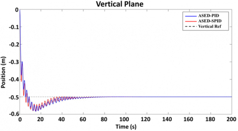
Subsequently, the output responses on horizontal and vertical planes, respectively for TRMS system with the implementation of proposed SPID and PID controllers are illustrated in Figure 6 and Figure 7, respectively. The reference signal is represented by dotted line while the red line and blue line denote to the proposed SPID controller and PID controller, respectively. Therefore, the output responses are recorded in Table 3 and discusses the controller performance in terms of rise time (Tr), settling time (Ts), overshoot (OS), steady-state error (ess) on horizontal and vertical planes. Notice that the line of PID and proposed SPID controllers are looked like overlapping on horizontal and vertical planes. Thus, the result on horizontal plane indicates that proposed SPID controller produce a smaller overshoot of 10.7676% which is reduced 12.8672% compared to PID controller. Besides, the performance on vertical plane performs that overshoot of SPID controller is slightly smaller with 0.369% compared to PID controller.
Figure 6. The response of TRMS on horizontal plane
Figure 7. The response of TRMS on vertical plane
Based on Table 3, the performance of proposed SPID controller on horizontal and vertical plane for TRMS system is still dominating majority the output response in terms of Tr, Ts and ess even though PID controller produces a smaller Tr on horizontal plane. Moreover, the results in term of Tr demonstrates that the proposed SPID controller has improvement by reduced at 0.015s compared to PID controller on vertical plane whereas PID controller produces a shorter of Tr which is shorted at 0.7222s compared to proposed SPID controller on horizontal plane. Additionally, the comparison of Ts results between the proposed SPID controller and PID controller on horizontal and vertical planes, it had shorted at least 32.598 s and 7.89s, respectively. The results indicate that proposed SPID controller has improvement in term of ess on horizontal and vertical planes which reduced at 0.0004% and 0.0006% compared to PID controller.
Table 3. The output responses of controllers on horizontal and vertical planes for TRMS system
|
Controller |
Horizontal |
Vertical |
||
|
PID |
SPID |
PID |
SPID |
|
|
Tr (s) |
2.6749 |
3.3971 |
3.0585 |
3.0432 |
|
Ts (s) |
132.00 |
99.4020 |
94.26 |
86.37 |
|
OS (%) |
23.6348 |
10.7676 |
16.6757 |
16.3067 |
|
ess (%) |
0.0024 |
0.0020 |
0.0042 |
0.0036 |
On the other hand, the overall performance comparison analysis in terms of objective function, J, total norm of error, $\bar{e}_1+\bar{e}_2$ and total norm of output, $\bar{u}_h+\bar{u}_v$ between proposed SPID and PID controllers on TRMS is recorded in Table 4. The findings indicate that the performances of proposed SPID controller are outperformed for the TRMS which produced smallest J, $\bar{e}_1+\bar{e}_2$ and $\bar{u}_h+\bar{u}_v$. The simulation result shows that the proposed SPID controller produced 6.84% improvement of control accuracy, Jψ compared to the controller of PID. Moreover, the proposed controller reduces more than 6.38% of $\bar{e}_1+\bar{e}_2$ compared to PID controller. In addition, the controller of proposed SPID has great improvement in terms of $\bar{u}_h+\bar{u}_v$ by reduced at least 4.25% compared to PID controller.
Table 4. The numerical results on TRMS system
|
Controller |
PID |
SPID |
|
J |
5218.40 |
4861.50 |
|
$\bar{e}_1+\bar{e}_2$ |
4.6792 |
4.3806 |
|
$\bar{u}_h+\bar{u}_v$ |
43.5669 |
41.7148 |
Consequently, the overall performances on horizontal and vertical planes of TRMS demonstrate the proposed SPID controller is proven that it is outperforms compared to the controller of PID in terms of rise time (Tr), settling time (Ts), overshoot (OS), steady-state error (ess). The importance of results in terms of objective function, J, total norm of error, $\bar{e}_1+\bar{e}_2$ and total norm of output, $\bar{u}_h+\bar{u}_v$ demonstrate significantly that the proposed SPID controller in control accuracy by the implementation of ASED method is better than PID controller towards the operating of TRMS system.
5.2 Performance index
The stability of controller’s performance evaluation regarding the Integral-Absolute-Error (IAE), Integral-Square-Error (ISE), Integral- Time-Absolute-Error (ITAE) and Integral-Square-Error (ITSE) is recorded in this sub-section. Therefore, mathematical formulation of these performance indicators is formulated by:
$\mathrm{IAE}=\int_{t_0}^{t_f}|e(t)| d t$, (32)
$\mathrm{ISE}=\int_{t_o}^{t_f} e^2(t) d t$, (33)
$\mathrm{ITAE}=\int_{t_0}^{t_f} t|e(t)| d t$, (34)
and
$\mathrm{ITSE}=\int_{t_0}^{t_f} t e^2(t) d t$ (35)
Table 5 tabulates the numerical results of proposed SPID controller and PID controller in terms of IAE, ISE, ITAE and ITSE. As observed, the proposed SPID controller still outperforms compared to PID controller by obtaining the smaller values of IAE, ISE, ITAE and ITSE for $\bar{e}_1$ and $\bar{e}_2$. In the result of $\bar{e}_1$ for the proposed SPID controller, the values are recorded as 2.2009, 0.4081, 26.6611 and 1.0944 of IAE, ISE, ITAE and ITSE, respectively. Meanwhile, the result of IAE, ISE, ITAE and ITSE are evaluated by PID controller that produced 0.62%, 8.68%, 3.68% and 0.78% larger compared to proposed SPID controller, respectively. The comparison of IAE, ISE, ITAE and ITSE for $\bar{e}_2$, the proposed SPID controller has improvement by reduced at least 12.61%, 11.54%, 20.23% and 23.50% compared to PID controller, respectively. Consequently, it is confirmed that the proposed SPID controller has significantly improvement by optimized through ASED method for the stability of controller performance compared to PID controller. The overall performance presents the proposed SPID controller is closest to the reference signal compared to PID controller with attaining the minimum value of IAE, ISE, ITAE and ITSE.
Table 5. The performance of IAE, ISE, ITAE and ITSE for TRMS system
|
Controller |
PID |
SPID |
||
|
$\bar{e}_1$ |
$\bar{e}_2$ |
$\bar{e}_1$ |
$\bar{e}_2$ |
|
|
IAE |
2.2147 |
2.4783 |
2.2009 |
2.1659 |
|
ISE |
0.4469 |
0.3128 |
0.4081 |
0.2767 |
|
ITAE |
27.6790 |
40.7073 |
26.6611 |
32.4703 |
|
ITSE |
1.1030 |
1.6726 |
1.0944 |
1.2796 |
In conclusion, this current research investigated a novel data-driven Sigmoid PID controller for horizontal and vertical planes of TRMS which is tuned through the ASED algorithm. The experimental results show that the proposed method successfully minimizes 6.84% of the objective function J(ψ) compared to conventional controller for achieving the convergence accuracy during optimization process. Besides, the proposed SPID controller successfully reduces more than 6.38% of $\bar{e}_1+\bar{e}_2$ and 4.25% of $\bar{u}_h+\bar{u}_v$ compared to conventional controller on TRMS. Moreover, the proposed SPID controller produces highly responsive output responses in terms of rise time (Tr), settling time (Ts), overshoot (OS), steady-state error (ess) on horizontal and vertical planes compared to the existing controller. Furthermore, the robustness analysis in terms of controller stability reveals that proposed SPID controller has best robustness by dominating in most of the IAE, ISE, ITAE and ITSE. Therefore, the performance results of the proposed SPID controller are satisfactory for implementation on the TRMS system.
This work has been partially funded through Grant FRGS/1/2021/ICT02//UMP/03/3 (Universiti Malaysia Pahang Reference: RDU 210117) under the governance of Malaysia’s Ministry of Higher Education.
[1] Jin, Z., Nie, L., Li, D., Tu, Z., Xiang, J. (2022). An autonomous control framework of unmanned helicopter operations for low-altitude flight in mountainous terrains. Drones, 6(6): 150. https://doi.org/10.3390/drones6060150
[2] Zischinsky, T., Dorffner, L., Rottensteiner, F. (2000). Application of a new model helicopter system in architectural photogrammetry. International Archives of Photogrammetry and Remote Sensing, 33(B5/2; PART 5): 959-959.
[3] Kannan, P.S., Sheenu, P. (2017). Advanced control of twin rotor MIMO system. International Journal of Advanced Research Trends in Engineering and Technology, 4(6): 166-173.
[4] Kannad, H.V. (2015). Control of twin rotor mimo system (TRMS) using pid controller. Corpus ID: 14175847.
[5] Pandey, S. K., Dey, J., Banerjee, S. (2020). Design of optimal PID controller for control of twin rotor MIMO system (TRMS). In: Singh, S., Pandey, R., Panigrahi, B., Kothari, D. (eds) Advances in Power and Control Engineering. Lecture Notes in Electrical Engineering, vol. 609. Springer, Singapore. https://doi.org/10.1007/978-981-15-0313-9_7
[6] Pathan, E., Khan, M.H., Aslam, M.K., Asad, M., Arshad, H., Rabani, M.I. (2021). A multivariable twin-rotor system control design. Engineering, Technology & Applied Science Research, 11(1): 6626-6631. https://doi.org/10.48084/etasr.3947
[7] Sivadasan, J., Willjuice Iruthayarajan, M. (2018). Tuning of nonlinear PID controller for TRMS using evolutionary computation methods. Tehnički vjesnik, 25(Supplement 1): 105-111. https://doi.org/10.17559/TV-20170612090511
[8] Rao, V.S., George, V.I., Kamath, S., Shreesha, C. (2017). Reliable robust PID controller design for TRMS. In 2017 11th Asian Control Conference (ASCC), Gold Coast, QLD, Australia, pp. 565-569. https://doi.org/10.1109/ASCC.2017.8287232
[9] Pandey, S.K., Dey, J., Banerjee, S. (2016). Design and real-time implementation of robust PID controller for Twin Rotor MIMO System (TRMS) based on Kharitonov's theorem. In 2016 IEEE 1st International conference on power electronics, intelligent control and energy systems (ICPEICES), Delhi, India, pp. 1-6. https://doi.org/10.1109/ICPEICES.2016.7853106
[10] Valluru, S.K., Singh, M., Dharavath, A. (2020). Design and experimental implementation of multi-loop LQR, PID, and LQG controllers for the trajectory tracking control of twin rotor MIMO system. In: Choudhury, S., Mishra, R., Mishra, R., Kumar, A. (eds) Intelligent Communication, Control and Devices. Advances in Intelligent Systems and Computing, vol. 989. Springer, Singapore. https://doi.org/10.1007/978-981-13-8618-3_62
[11] Ateş, A., Alagöz, B.B., Yeroğlu, C., Alisoy, H. (2015). Sigmoid based PID controller implementation for rotor control. In 2015 European Control Conference (ECC), Linz, Austria, pp. 458-463. https://doi.org/10.1109/ECC.2015.7330586
[12] Valluru, S.K., Kumar, R., Kumar, R. (2020). Design and real time implementation of fmincon, MOGA tuned IO-PID and FO-PIλDμ controllers for stabilization of TRMS. Procedia Computer Science, 171: 1241-1250. https://doi.org/10.1016/j.procs.2020.04.305
[13] Sain, D., Swain, S.K., Saha, A., Mishra, S.K., Chakraborty, S. (2019). Real-time performance analysis of FOI-PD controller for twin rotor MIMO system. IETE Technical Review, 36(6): 547-567. https://doi.org/10.1080/02564602.2018.1528190
[14] Chaudhary, S., Kumar, A. (2019). Control of twin rotor mimo system using 1-degree-of-freedom PID, 2-degree-of-freedom PID and fractional order PID controller. In 2019 3rd International Conference on Electronics, Communication and Aerospace Technology (ICECA), Coimbatore, India, pp. 746-751. https://doi.org/10.1109/ICECA.2019.8821923
[15] Kavuran, G., Ates, A., Alagoz, B.B., Yeroglu, C. (2017). An experimental study on model reference adaptive control of TRMS by error-modified fractional order MIT rule. Control Engineering and Applied Informatics, 19(4): 101-111.
[16] Mishra, S.K., Purwar, S. (2014). To design optimally tuned FOPID controller for twin rotor MIMO system. In 2014 Students Conference on Engineering and Systems, Allahabad, India, pp. 1-6. https://doi.org/10.1109/SCES.2014.6880118
[17] Valluru, S.K., Kumar, R. (2019). Trajectory tracking control of TRMS using FO-PID and FOI-PD controllers: An experiment. In 2019 3rd International Conference on Recent Developments in Control, Automation & Power Engineering (RDCAPE), Noida, India, pp. 319-322. https://doi.org/10.1109/RDCAPE47089.2019.8979086
[18] Valluru, S.K., Kumar, R., Kumar, R. (2019). Design of precise FLC for trajectory tracking and stabilization of twin rotor MIMO system. In 2019 IEEE 6th International Conference on Engineering Technologies and Applied Sciences (ICETAS), Kuala Lumpur, Malaysia, pp. 1-6. https://doi.org/10.1109/ICETAS48360.2019.9117570
[19] Ilyas, M., Abbas, N., UbaidUllah, M., Imtiaz, W.A., Shah, M.A.Q., Mahmood, K. (2016). Control law design for twin rotor MIMO system with nonlinear control strategy. Discrete Dynamics in Nature and Society, 2016: 2952738. https://doi.org/10.1155/2016/2952738
[20] Rashad, R., El-Badawy, A., Aboudonia, A. (2017). Sliding mode disturbance observer-based control of a twin rotor MIMO system. ISA Transactions, 69: 166-174. https://doi.org/10.1016/j.isatra.2017.04.013
[21] Mustafa, S., Khan, I., Khan, Q. (2017). Adaptive gain sliding mode based output tracking control of twin rotor MIMO system. In 2017 13th International Conference on Emerging Technologies (ICET), pp. 1-6.
[22] Ghellab, M.Z., Zeghlache, S., Bouguerra, A. (2018). Real time implementation of fuzzy gain-scheduled PID controller for twin rotor MIMO system (TRMS). Advances in Modelling and Analysis C, 73(4): 137-149. https://doi.org/10.18280/ama_c.730403
[23] Bandyopadhyay, S., Pramanick, P., Dey, C. (2021). Fuzzy Rule-Based supervisory PID Auto-Tuner for TRMS process. In: Nath, V., Mandal, J.K. (eds) Proceedings of the Fourth International Conference on Microelectronics, Computing and Communication Systems. Lecture Notes in Electrical Engineering, vol. 673. Springer, Singapore. https://doi.org/10.1007/978-981-15-5546-6_55
[24] Jahed, M., Farrokhi, M. (2013). Robust adaptive fuzzy control of twin rotor MIMO system. Soft Computing, 17: 1847-1860. https://doi.org/10.1007/s00500-013-1026-6
[25] Juang, J.G., Liu, W.K., Lin, R.W. (2011). A hybrid intelligent controller for a twin rotor MIMO system and its hardware implementation. ISA Transactions, 50(4): 609-619. https://doi.org/10.1016/j.isatra.2011.06.006
[26] Shih, C.L., Chen, M.L., Wang, J.Y. (2008). Mathematical model set‐point stabilizing controller design of a twin rotor MIMO system. Asian Journal of Control, 10(1): 107-114. https://doi.org/10.1002/asjc.11
[27] Zapata, B., Heredia, J., Proaño, J. (2020). Design and evaluation of the PID, SMC and MPC controllers by state estimation by kalman filter in the TRMS system. In: Botto-Tobar, M., Zambrano Vizuete, M., Díaz Cadena, A. (eds) Innovation and Research. CI3 2020. Advances in Intelligent Systems and Computing, vol. 1277. Springer, Cham. https://doi.org/10.1007/978-3-030-60467-7_43
[28] Ahmad, M.A., Ismail, R.R. (2017). A data-driven sigmoid-based PI controller for buck-converter powered DC motor. In 2017 IEEE Symposium on Computer Applications & Industrial Electronics (ISCAIE), Langkawi, Malaysia, pp. 81-86. https://doi.org/10.1109/ISCAIE.2017.8074954
[29] Ramesh, N.H.A.R., Ghazali, M.R., Ahmad, M.A. (2021). Sigmoid PID based adaptive safe experimentation dynamics algorithm of portable duodopa pump for Parkinson’s disease patients. Bulletin of Electrical Engineering and Informatics, 10(2): 632-639. https://doi.org/10.11591/eei.v10i2.2542
[30] Liu, D., Tang, Z., Pei, Z. (2015). Variable structure compensation PID control of asymmetrical hydraulic cylinder trajectory tracking. Mathematical Problems in Engineering, 2015: 890704. https://doi.org/10.1155/2015/890704
[31] Shao, X., Wang, H., Liu, J., Tang, J., Li, J., Zhang, X., Shen, C. (2017). Sigmoid function based integral-derivative observer and application to autopilot design. Mechanical Systems and Signal Processing, 84: 113-127. https://doi.org/10.1016/j.ymssp.2016.05.045
[32] Shao, X.L., Wang, H.L. (2014). Nonlinear tracking differentiator based on improved sigmoid function. Control Theory & Applications, 31(8): 1116-1122.
[33] Feedback Instruments Limited (1998). Twin Rotor, M.I.M.O. (1998). System 33–220 user manual. Crowborough, UK. [Online]. Available: https://scholar.google.com/scholar?q=Feedback Co., 1998. Twin rotor MIMO system 33-220 user manual.
[34] Ghazali, M.R., Ahmad, M.A., Ishak, H. (2021). A data-driven sigmoid-based secretion rate of neuroendocrine-PidControl for TRMS system. In 2021 IEEE 11th IEEE Symposium on Computer Applications & Industrial Electronics (ISCAIE), Penang, Malaysia, pp. 1-6. https://doi.org/10.1109/ISCAIE51753.2021.9431795
[35] Feedback Instruments Ltd. Twin Rotor Mimo System ADVANCED TEACHING MANUAL 1 33-007-4M5.
[36] Ghazali, M.R., Ahmad, M.A., Ismail, R.R. (2020). Data-driven neuroendocrine-PID controller design for twin rotor MIMO system. In Journal of Physics: Conference Series, 1529(4): 042080. https://doi.org/10.1088/1742-6596/1529/4/042080