Fatima Moulay* | Assia Habbati | Oukli Mimouna
© 2022 IIETA. This article is published by IIETA and is licensed under the CC BY 4.0 license (http://creativecommons.org/licenses/by/4.0/).
OPEN ACCESS
Considering the environmental effects and the shortage of fossil fuels, research encourages us towards the development and use of more and more renewable energies such as the autonomous photovoltaic system which is very much used for rural applications such as solar lighting, battery charging, etc. The beginning of our study describes the photovoltaic effect and the current-voltage and power-voltage characteristics of a mathematical model of a cell with a single diode. This allows us to model a solar panel and get an idea of the behavior of the field and the photovoltaic generator. The model predicts the behavior and characteristics of the PV model using the Matlab/Simulink platform. Connected to a basic circuit, the constant DC source voltage step-up converter first and to the PV system last, allows us to conclude that the presence of power electronics is essential in the photovoltaic system in order to adapt and d Ensuring its proper functioning and satisfactory results suggest the effectiveness of this model.
PV modelling, photovoltaic system, DC-DC boost converter
Solar energy is by nature widely available everywhere in the world, even if the countries located in certain zones are privileged because the solar radiation is very intense there. Solar is for the moment only an ultra-minority in the global energy mix (1%), but it is experiencing rapid development which, according to forecasts by the IEA (the International Energy Agency), is expected to continue over the next few years [1].
The main solar power generation capacities are currently installed in China, the United States, Germany, Japan and Italy. India could also quickly catch up with these countries.
Renewable energies such as wind energy, solar energy, biomass energy, are promising solutions to compete with mass energy sources such as fossil and nuclear energies [2].
By renewable energy, we mean energy from the sun, wind, heat from the earth, water or biomass. Unlike fossil fuels, renewable energies are energies with unlimited resources. If we look at solar energy in particular, we will notice that solar radiation is distributed over the entire surface of the earth. No country will have to sell the resource, it will rather sell the technology [3].
The photovoltaic effect manifests itself in the form of a potential difference between the two sides of a semiconductor P-N junction when this junction receives solar radiation of adequate wavelength and connected at the end with a load, the material most used industrially is based on silicon [4].
Such a system consists of a field of modules and a set of components which adapt the electricity produced by the modules to the specifications of the receivers.
The photovoltaic generator is the only direct converter to transform solar radiation into electrical energy, but it is not capable of generating energy suitable for charging or connecting to the electrical grid. One or two adaptation steps should always be used. This is the role of power converters which are as important as they are indispensable in photovoltaic systems [5].
Most household appliances operate with a voltage of 220V, 50Hz. However, energy sources available in isolated environments such as batteries or solar panels provide DC voltages between 12 and 24V. In order to use these energy sources to operate 220V, 50Hz appliances, it is necessary to use inverters that convert direct current to alternating current. Generally, two converters are required to adapt the energy produced by the photovoltaic generator; a DC/DC converter, object of our paper, to raise or lower the voltage to the desired value and an inverter to obtain the AC form from the DC form delivered by the photovoltaic generator [6].
This paper deals with the modelling and the study of a PV module connected to a boost converter which supplies a resistive load that can be a lamp or another receiver for domestic use.
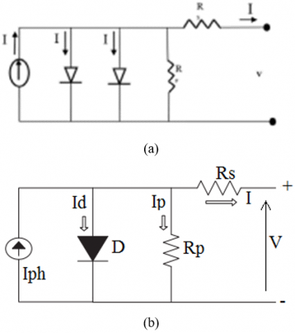
There are mathematical models of the characteristic current-voltage of the photovoltaic cell. However, the most practical by their relative simplicity in the calculation are the single exponential model (a single diode), in which, the obscurity current (diode current), representing uniquely the saturation current resulting of the diffusion phenomenon and the two exponential model (two diodes) representing both the components, diffusion and recombination [7].
Figure 1. Two and one Diode model of PV cell
The model of one diode (Figure 1), has the advantage of being simple, it allows to obtain the static behavior of a PV cell under polarization
$I=I_{p \hbar}-I_d-I_p$ (1)
I: The current of the PV cell,
$I_{p h}$: The, photon current it is proportional to the irradiance,
$I_d$: The current flowing in the ideal diode D (diode in parallel models the junction),
$I_p$: The current flowing through the shunt resistor.
There are several ways to present and calculate the current of a PV cell (1). For this, we chose a simplified and improved mathematical model [8], and the I-V characteristic can be written as follows:
$I_p=\frac{V+R_s I}{R_p}$ (2)
$R_p$: The shunt resistance (parallel).
The photocurrent is given by:
$I_{p h}=\left(\frac{G}{G_{r e f}}\right)\left(I_{p h, r e f}+\mu c c\left(T_c-T_{c, \text { ref }}\right)\right)$ (3)
G: Irradiance,
Gref: Irradiance in standard conditions=1000W / m²,
Tc,ref: The temperature of the cell under standard conditions=25℃,
Tc: The temperature of the cell (℃),
µcc: Temperature Coefficient of the DC current (A / ℃),
Iph,ref: The photocurrent.
Latter can easily be measured from the manufacturer's characteristic (I-V) to standard conditions.
The diode current is given by Shockley's equation:
$I_d=I_0\left[\exp \left(\frac{e\left(V+I R_s\right.}{\lambda K T_c}\right)-1\right]$ (4)
V : The voltage,
Rs : Series resistance,
λ : is a coefficient characterizing the power variation as a function of temperature,
K : The Boltzmann constant,
e : The charge of the electron,
I0 : The saturation current.
We have:
$I_0=D T_c^3 \exp \left(\frac{-e \varepsilon_G}{n K T_c}\right)$ (5)
D : The diffusion factor of the diode,
εG : The width of the forbidden band (eV).
To eliminate the term D, the two equations are divided into parts:
$I_0=I_{0, \text { ref }}\left(\frac{T_c}{T_{c, \text { ref }}}\right)^3 \exp \left[\left(\frac{e \varepsilon_G}{n K}\right)\left(\frac{1}{T_{c, \text { ref }}}-\frac{1}{T_c}\right)\right]$ (6)
It is necessary to write the characteristic equation I (V):
$I=I_{p h}-I_0\left[\exp \left(\frac{e\left(V+R_s I\right.}{\lambda K T_c}\right)-1\right]-\frac{V+R_s I}{R_p}$ (7)
We can write the following three relations:
$I_{c c, r e f}=I_{p h, r e f}-I_{0, \text { ref }}\left[\exp \left(\frac{e I_{c c, r e f} \quad R_s}{\lambda K T_{c, \text { ref }}}\right)-1\right]$ (8)
$0=I_{p h, r e f}-I_{0, \text { ref }}\left[\exp \left(\frac{e V_{c o, r e f}}{\lambda K T_{c, e f} \quad }\right)-1\right]$ (9)
$I_{p m, r e f}=I_{p h, r e f}-I_{0, r e f}\left[\exp \left(\frac{e\left(V_{p m, r e f} \quad +I_{p m, r e f} \quad R_s\right.}{\lambda K T_{c, r e f}}\right)-1\right]$ (10)
So it can be deduced that [1-6].
$I_{c c, r e f} \approx I_{p h, r e f}$ (11)
By replacing $I_{p h, r e f}$ with $I_{c c, r e f}$ in Eq. (9):
$0 \approx I_{c c, r e f}-I_{0, \text { ref }} \exp \left(\frac{e V_{c o, r e f}}{\lambda K T_{c, \text { ref }} \quad }\right)$ (12)
$I_{0, r e f}=I_{c c, r e f} \exp \left(\frac{-e V_{c o, r e f}}{\lambda K T_{c, r e f} \quad }\right)$ (13)
For the calculation of $I_0$, we replace in Eq. (6), and for $I_{p h}$ in Eq. (3).
For a photovoltaic generator composed of Ns modules in series and Np modules in parallel, there will be:
$V_{p v}=N_s V$ (14)
$I_{p v}=N_p I$ (15)
The Figure 2 gives the PV module Matlab/SIMULINK model.
Figure 2. PV model under Simulink
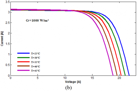
The evolution of the I−V characteristic as a function of temperature shows that the current increases very rapidly when the temperature rises and generates a less pronounced decrease in the open circuit voltage (Figure 3).
Figure 3. (a) I (V) curves and (b) P (V) curves of a panel at various irradiances at T=25℃
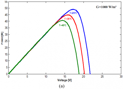
The high temperature lowers the open circuit voltage for fixed sunlight; therefore, the maximum power drops (Figure 4).
Figure 4. The influence of temperature on the (a) I(V) curves at G=1000 W/m2 and on the (b) P(V)
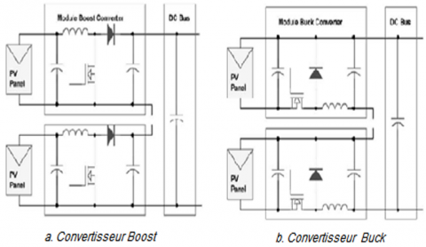
Like inverters, converters are essential for integrating PV electricity into the grid. Indeed, the fluctuation of this energy constitutes a real problem of adaptation. It is constantly necessary to stabilize, reduce or often raise the tension. Several topologies are proposed in the literature, we present the most appropriate and the most studied: Boost, Buck, Buck-boost and Cuk. Figure 5 presents four possible topologies of non-isolated DC/DC converters suitable for PV panels [9].
3.1 Buck converter
A chain connection of series of buck modules, as in Figure 5.b, allows total independence with respect to the output voltage and therefore the power, while the output currents are necessarily equal because of the connection in series. In addition, the internal freewheeling diode of the Buck converter allows the inactive module to which it is associated to be kept automatically on without causing a short-circuit of the DC source.
3.2 Buck-boost converter
They are choppers capable of operating in two ways (Buck-Boost) where the average output voltage is lower or higher than that of the input [10, 11].
Figure 5. Diagrams of the different converter topologies DC/DC for PV connected to a power grid
3.3 Ćuk converter
Unlike other types of converters, which use an inductor, a Ćuk converter uses a capacitor to store energy [12].
3.4 Boost converter
It is very suitable for boosting the direct voltage generated by the PV installation to the value necessary to convert it into alternating voltage and therefore frees up the use of the transformer (Figure 6). The characteristic of the Boost is that it allows with the minimum required voltage of 340V of the direct bus to reach the alternating voltage of 240 V for a connection to the network without a transformer and above all, with the fewest possible photovoltaic panels [13-15].
Figure 6. Circuit diagram of the Boost converter
At the beginning of this work, we took the simple example of a continuous source which feeds a boost converter and we proceeded to calculate the various parameters, to to reach the desired output, we removed the continuous source and we had it replaced with the photovoltaic system proposed in the model .In both cases, the service pulses are supplied by the PWM pulse generator [16, 17].
4.1 System data
For our case study:
4.2 Determination of parameters
In this study example, we take:
the output voltage Vo =100 volt
Vs =70 volt
switching frequency Fs=1kHz,
R load =50Ω
r=0.5%.
4.2.1 Duty cycle (D)
$D=1-\frac{V s}{V_0}$ (16)
$D=1-\frac{70}{100}=0.3$ (17)
4.2.2 Value of inductor (L)
Calculate minimum inductance
$L_{\min }=\frac{D(1-D)^2 R}{2 * f}$ (18)
$L_{\min }=\frac{0.3(1-0.3)^2 * 50}{2 * 1000}=3675 \mu H$ (19)
Calculate 25% larger than minimum inductance
$L=1.25 * L_{\min }$ (20)
$L=1.25(3675)=4593.75 \mu H$
4.2.3 Calculate minimum capacitance
$C=\frac{D}{R r f}$ (21)
$C=\frac{0.3}{50 * 0.005 * 1000}=1200 \mu F$ (22)
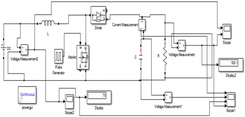
Figure 7. Equivalent circuit of the boost converter
Under MATLAB / Simulink and using different blocks of the library, we have connected the diagram of the Figure 7, which is an example of a resistive load, supplied by a continuous source using a step-up converter (Boost) [18-21].
The gate pulse needed to trigger the circuit is supplied by the pulse generator.
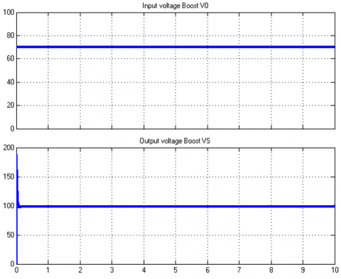
Figure 8 represents the outputs of the converter.
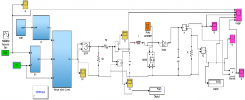
We take the PV module shown in Figure 7 and we connect the boost DC-DC converter for main to have a boost input voltage of 70 volts and a voltage boost output of 100 volts or load voltage for our case we took a resistive load of 50 ohms.
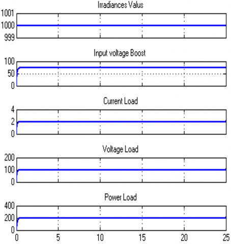
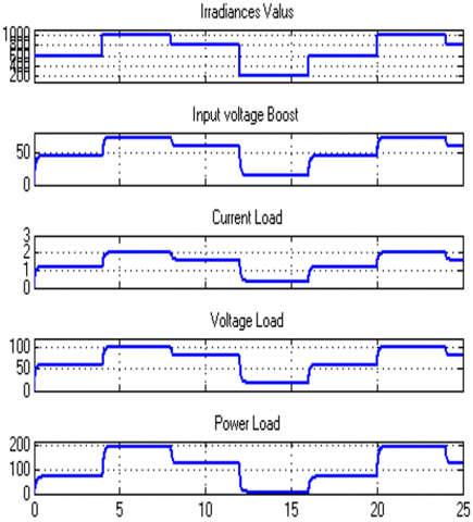
After simulation ,the results are given by Figure 10 for constant irradiance at a value of 1000W/m² and Figure 11 by variying the irradiances.
Figure 10 represents the output current, voltage and power waves form.
For a constant irradiance, we note the reliability of our proposed model, since the goal is to have a voltage at the output of the boost higher than that given by the photovoltaic generator which the values have been defined beforehand (V0=100 Volts and Vs=70 Volts).
By varying the irradiances with the bloc of Simulink Repeating Sequence Stair at Vector of output values: [600 1000 800 200] in Figure 11, the current, voltage and the power in the load vary with the irradiances.
Figure 8. Output voltage waveform of simple boost
Figure 9. PV and boost converter with impulsion generator
Figure 10. Output voltage waveform of PV system connected boost converter with impulsion generator
Figure 11. Output voltage waveform of PV system
The work summarizes, modeling of system elements and simulation for variations in temperature and irradiance, the performance of a PV generator is strongly influenced by these two parameters.
The one-diode model is the most classic and the most used in the literature, it takes physical phenomena into account, it involves a current generator for modeling the luminous flux, a diode for the junction polarization phenomena and two resistors (series and shunt) for losses.
The strength of this work is the design of the model with the contribution of the boost converter, which is answered in the use of systems aimed at increasing the input voltages and supplying loads with desired outputs.
[1] Al-Shetwi, A.Q., Zahim, S.M., Lina, R.N. (2015). A review of the fault ride through requirements in different grid codes concerning penetration of PV system to the electric power network. ARPN Journal of Engineering and Applied Sciences, 10(21): 9906-9912.
[2] Subudhi, B., Pradhan, R. (2013). A comparative study on maximum power point tracking techniques for photovoltaic power systems. IEEE Transactions on Sustainable Energy, 4: 89-98. https://doi.org/10.1109/TSTE.2012.2202294
[3] Huynh, D.C., Nguyen, T.N., Dunnigan, M.W., Mueller, M.A. (2013). Dynamic particle swarm optimization algorithm based maximum power point tracking of solar photovoltaic panels. 2013 IEEE International Symposium on Industrial Electronics, pp. 1-6. https://doi.org/10.1109/ISIE.2013.6563616
[4] Kumari, S., Babu, S., Babu, A.K. (2012). Design and analysis of P&O and IP&O MPPT technique for photovoltaic system. International Journal of Modern Engineering Research, 2(4): 2174-2180.
[5] Kollimalla, S.K., Mishra, M.K. (2014). Variable perturbation size adaptive P&O MPPT algorithm for sudden changes in irradiance. IEEE Transactions on Sustainable Energy, 5(3): 718-728. https://doi.org/10.1109/TSTE.2014.2300162
[6] Bellia, H., Youcef, R., Fatima, M. (2014). A detailed modeling of photovoltaic module using MATLAB. NRIAG Journal of Astronomy and Geophysics, 3: 53-61. https://doi.org/10.1016/j.nrjag.2014.04.001
[7] Makhlouf, M., Messai, F., Benalla, H. (2012). Modeling and control of a single-phase grid connected photovoltaic system. Journal of Theoretical and Applied Information Technology, 37(2): 289-296.
[8] Dris, M., Djilani, B. (2018). Hybrid system power generation wind-photovoltaic connected to the electrical network 220 kV. International Journal of Applied Power Engineering (IJAPE), 7(1): 10-17. http://dx.doi.org/10.11591/ijape.v7.i1.pp10-17
[9] Al-Shetwi, A.Q., Sujod, M.Z., Tarabsheh, A., Altawil, I.A. (2016). Design and economic evaluation of electrification of small villages in rural area in Yemen using stand-alone PV system. International Journal of Renewable Energy Research (IJRER), 6(1): 290-298. https://doi.org/10.20508/ijrer.v6i1.3212.g6785
[10] Muthuramalingam, M., Manoharan, P.S. (2014) A photovoltaic power system using a high step-up converter for DC load applications. Energy Conversion and Management, 86: 286-299.
[11] Zhou Z., Holland P., Igic, P. (2014). MPPT algorithm test on a photovoltaic emulating system constructed by a DC power supply and an indoor solar panel. Energy Conversion and Management, 85: 460-469. https://doi.org/10.1016/J.ENCONMAN.2014.06.007
[12] Pires, V.F., Romero-Cadaval, E., Vinnikov, D., Roasto, I., Martins, J.F. (2014). Power converter interfaces for electrochemical energy storage systems - A review. Energy Conversion and Management, 86: 453-475. https://doi.org/10.1016/J.ENCONMAN.2014.05.003
[13] Ahmad, S., Albatsh, F.M., Mekhilef, S., Mokhlis, H. (2014). Fuzzy based controller for dynamic Unified Power Flow Controller to enhance power transfer capability. Energy Conversion and Management, 79: 652-665. https://doi.org/10.1016/J.ENCONMAN.2013.12.042
[14] Guerrero-Rodríguez, N.F., Alexis, B.B. (2014). Modelling, simulation and experimental verification for renewable agents connected to a distorted utility grid using a Real-Time Digital Simulation Platform. Energy Conversion and Management, 84: 108-121. http://dx.doi.org/10.1016/j.enconman.2014.04.020
[15] Yau, H.T., Lin, C.J., Liang, Q.C. (2013). PSO based PI controller design for a solar charger system. The Scientific World Journal, 3: 815280. https://doi.org/10.1155/2013/815280
[16] Farhat, M., Barambones, O., Sbita, L., Fleh, A. (2017). A robust MPP tracker based on sliding mode control for a photovoltaic based pumping system. International Journal of Automation and Computing, 14: 489-500. https://doi.org/10.1007/S11633-016-0982-6
[17] Liu, C., Wu, B., Cheung, R. (2004). Advanced algorithm for MPPT control of photovoltaic systems. Canadian Solar Buildings Conference, Montreal, pp. 20-24.
[18] Fadili, A.E., Giri, F., Magri, A.E. (2013). Reference voltage optimizer for maximum power tracking in single-phase grid-connected photovoltaic systems. Journal of Control and Systems Engineering, 1(2): 57-66.
[19] Loukriz, A., Saigaa, D., Drif, M., Hadjab, M., Houari, A., Messalti, S., Saeed, M.A. (2021). A new simplified algorithm for real-time power optimization of TCT interconnected PV array under any mismatch conditions. Journal Européen des Systèmes Automatisés, 54(6): 805-817. https://doi.org/10.18280/jesa.540602
[20] A. El Halim, A.A., Bayoumi, E.H. (2021). Using a new combination of P&O and ICM methods for the experimental validation of MPPT efficacy. Journal Européen des Systèmes Automatisés, 54(6): 797-804. https://doi.org/10.18280/jesa.540601
[21] Lorenzini, G., Kamarposhti, M.A., Solyman, A. (2021). Maximum power point tracking in the photovoltaic module using incremental conductance algorithm with variable step length. Journal Européen des Systèmes Automatisés, 54(3): 395-402. https://doi.org/10.18280/jesa.540302