Mohammed Abdeldjalil Djehaf* | Youcef Islam Djilani Kobibi | Mohammed Khatir | Mohammed Ouadafraksou
© 2022 IIETA. This article is published by IIETA and is licensed under the CC BY 4.0 license (http://creativecommons.org/licenses/by/4.0/).
OPEN ACCESS
In this paper, transient stability analysis of a detailed model multi-machine power system was carried out to focus on the impact of HVDC link on system stability by comparing the critical fault clearing times of two operational scenarios, namely an AC transmission system with and without parallel HVDC transmission. The advantage and performance of AC-DC transmission for the improvement of response to transient instability caused by phase to ground fault was researched by detail simulation carried out in MATLAB/SIMULINK.
High-Voltage Direct Current (HVDC) transmission, electric power system stability, transient stability, multi-machine power system, fault clearing time, wind farm
In order to enhance the power system stability, the development and research have never stopped. With the recent deregulation, the growing electricity demand, the growing implementation of decentralized renewable power sources, and the resulting long distances between the electricity production and the load centers, maintaining the power system stability is becoming even more difficult. The dynamic performance of the electrical power system components is influenced by the sensitivity of system variables with different characteristics and response rates to various perturbations or imperfections in the operation of the connected components of the system [1]. Hence, power system instability may happen in numerous behaviors subject to the system structure, operational mode, and the disturbance form [2].
The system is required to be able to survive several severe perturbations, like a line to ground fault. Usually, the short-circuit level at a bus is a good measure of the strength of the system at that specific point.
The reaction of the power system to a perturbation may include various devices. For example, a short-circuit on a basic component succeeded by its protective relays isolation results variations in load flows, bus voltages, generators rotor speeds; and other variables in the network that can jeopardize the operation of the system. Furthermore, the equipment used to protect power system components may react to variations in system variables and in that way disturb the power system operation.
The existing transmission lines are being pushed to their operating limits due to either steady-state or stability limits for power transmission between various regions of the world within the same area itself.
The issue of (HVAC) transmission especially in long distance transmission has prompted the development of High Voltage Direct Current (HVDC) transmission, because HVAC has stability issues with longer-distance transmission. HVDC transmission lines have various advantages and features, for example, the instantaneous power control, and the capability to improve transient and dynamic stability issues related to HVAC lines [3].
The work presented is primarily focused on large transient disturbances to investigate the time-varying performance of the network in the presence of the HVDC link.
Power system stability is defined by Kundur et al. [4] as the capability of the power system, for a given initial operational state, to recover operating balance condition after being exposed to a physical perturbation, with most system variables constrained so that nearly the entire system stays intact.
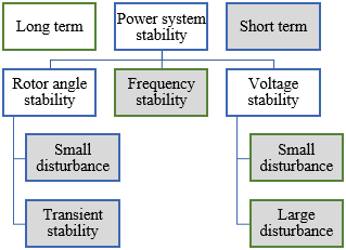
There are three kinds of stability issues in power system engineering namely; rotor angle stability, frequency stability and voltage stability. The power system is designed and run in a manner to be stable for a particular set of eventualities. The eventualities or contingencies generally considered are different types of short-circuit: Phase-to-ground, phase-to-phase-to-ground, or three phases.
Figure 1 demonstrates a possible characterization of power system stability into different categories and subcategories.
Figure 1. Classification of power system stability
The following sections will discuss voltage stability and rotor angle stability definitions and classification.
2.1 Rotor angle stability
Perturbing the system equilibrium leads to a speeding or slowing of the machines rotors and may lead to loss of synchronism that can happen between one motor and the rest of the system, or between several machines. Therefore, the ability of synchronous generators in a power system to maintain synchronism after being subjected to a perturbation is what defines rotor angle stability.
Every machine's input mechanical torque and output electromagnetic torque are balanced under steady-state constraints, keeping the speed constant. This balance is thrown off if the power system is disrupted, which causes the generators rotors to speed up or slow down. Instability may occur as a result of an increasing angular swing of a few generators, resulting in their loss of synchronism. Depending on the power-angle relationship, part of the load is transferred from the slow machine to the fast machine by the resulting angular difference. The power-angle relationship is extremely nonlinear. Increases in angular separation are followed by decreases in power transfer, which causes the angular separation to increase even further after a certain limit. If the system is unable to absorb the kinetic energy caused by these variations in rotor speed, instability results [4].
For any given circumstance, the stability of the system relies upon whether or not the deviations in angular positions of the rotors result in adequate restoring torque [5].
In a multi-machine synchronized systems, if the steady state conditions are disturbed, the angular separation between the various machines will vary. Generator that runs faster than others, will have their rotor advancing the slower machines’ rotor more. Accordingly, the relative rotor angle (δ) will increase between a faster and slower machine; and as per the power-angle curve, the faster machine will “take-over” some load forms the slower one (this is called the “restoring torque”). This will reduce the relative angular separation (δ) between the machines. Easy to conclude, that if restoring torques are adequate, the system will settle down, and it’s obtained by the control system of the generators mechanical power (steam / gas turbine flow control).
2.1.1 Large disturbance rotor angle stability or transient stability
The transient stability criteria include the aptitude of the power system to preserve synchronism when subjected to a significant transient disturbance, such as a short-circuit, at crucial spots on a transmission line, such as at a highly loaded generator bus at the line delivering bulk power in the case of AC transmission and close to the inverter converter in the case of HVDC transmission. The resulting system behavior includes large variations of generator rotor angles and is influenced by the nonlinear power-angle equation as follows [4].
Consider a single machine infinite bus (SMIB) system as shown in Figure 2:
Figure 2. Per phase equivalent circuit
The power angle equation is given by:
$P_S=\frac{E V \sin \delta}{X}$ (1)
Power angle curve is shown in the Figure 3.
Figure 3. Power angle curve
For a given mechanical power ($P_m$), there are two operating angles.
$\delta_0=\sin ^{-1}\left(\frac{P_m}{P_{\max }}\right)$
$\delta_{\max }=\pi-\delta_0$ (2)
$\delta_0$ is a stable equilibrium point.
$\delta_{\max }$ is an unstable equilibrium point.
Transient stability is determined by both the system's initial operating state and the degree of the disturbance [6].
The instability is typically shown as first swing instability due to aperiodic angular separation caused by a lack of synchronizing torque. However, dynamic instability may not always occur as a first swing instability tied to a single mode in large scale power systems. It can be resulting from the interaction between a local-plant swing mode and a slow interarea swing mode, which results in a significant trip of the rotor angle past the first swing. Additionally, it could result from nonlinear impacts on a single mode that cause instability after the first swing [7].
In transient stability studies, the timescale of interest is generally 3 to 5 seconds after the disturbance. For large-scale systems with significant inter-area swings, it can be increased to 10 – 20 seconds.
2.2 Voltage stability
Many power system failures have been attributed to voltage stability, even though low voltages may be associated with rotor angle divergence, the type of voltage collapse associated with voltage instability may occur in situations where angle stability is not a concern. Voltage stability depends on the capacity to maintain steady state voltages at all system buses after being exposed to a perturbation from a specified initial operating condition and to restore balance between load demand and load supply from the power system. The potential for instability manifests as a gradual drop or rise in the voltages of buses [4].
Loss of load in a region or the commutation of transmission lines and other components by their protection systems are possible impacts of voltage instability causing cascade outages. Some generators may lose synchronism as a result of these failures and disturbances or mode of operation that exceed the current limit [7-11].
Many studies have presented strategies to improve voltage stability using flexible AC transmission systems (FACTS), embedded generations (EG), high voltage direct current (HVDC), voltage source converter (VSC) [7-14].
Even with the present deployment of embedded generation and the associated benefits, the HVDC approach appears to be the best solution at the moment. i.e., it has not been as successful as solutions based on HVDC technology in terms of power system load reduction, improved voltage stability, and decreased workload for power system operators.
Voltage stability issues may also be experienced at the terminals of either back-to-back or long distance HVDC links [15, 16]. Typically, they are connected to weak ac systems via HVDC links and linked to the inverter or rectifier stations operation. This is due to the AC system's inability to produce the reactive power necessary by the converters to maintain an adequate system voltage.
The HVDC link control strategies impact significantly on such issues, meanwhile controls provide the references of active power and reactive power in the HVDC link. A modest increase in current order corresponding to the operating point resulting in a voltage drop, can induce an increase in reactive power [1].
Voltage instability occurs if the load on the AC transmission system exceeds its limit. The time frame for such a phenomenon is of the order of one second or less, making it relatively rapid. Likewise, voltage instability, which is a much slower process, can also be linked to the controls of the converter transformer tap-changer [16-18].
The interaction between the three kinds of stability can be resumed as follows [19]:
Rotor angle stability is basically generator stability. Voltage stability is basically load stability. Rotor angle stability depends on the ability of each synchronous machine to maintain equilibrium between electromagnetic torque and mechanical torque. Voltage stability depends on the system to maintain equilibrium between load demand and load supply.
If voltage collapse at a point in a transmission system it is an angle instability situation however if voltage collapse in a load area is a voltage instability.
The frequency stability is the ability of the system to maintain the frequency at an acceptable range after a disturbance, which means that it depends on the active power balance between the generation and demand. So, the frequency instability leads to rotor angle instability.
It is important to understand that the distinction between rotor angle stability and voltage stability is not due to a weak relationship between changes in active power / angle and reactive power / voltage amplitude. Indeed, the relationship is significant for transient stability, and both rotor angle stability and voltage stability are influenced equally by pre-disturbance active and reactive power flow. As a result, the distinction is based on the specific arrangement of opposing forces that are always imbalanced and the key system variable in which the consequent instability is evident [4].
Rapid growth of high-powered semiconductor power electronics-based devices have permitted advanced technologies such as HVDC to be functional in power systems to improve their performance.
In fact, the major advantages of HVDC in impacting power systems performance consists of the following [20-22]:
The above HVDC advantages would help the power network performance by facing the next problems relying upon the needed application:
Beside the basic function of bulk power transmission over long distances, HVDC system can be used in the interconnection of asynchronous systems especially with the massive integration of offshore wind power [9]. HVDC schemes may also be employed to enhance transient rotor angle stability of an electric power system operating in parallel with HVAC lines by controllable devices (e.g., HVDC links), specifically, their control actions [23, 24].
It is shown that by making use of fast control of HVDC converters for temporary increase of DC power during the fault and transient period, the system retarding torque can be improved [25-27]. It is further demonstrated in the refs. [27-29] that the simultaneous transmission of AC and DC power in one transmission line may lead to the improvement of transient rotor angle stability of the electric power system.
Faster power flow control might be done using dc transmission system converters, in contrast with the case by the ac transmission. The perturbation in the ac system can be removed instantly using the power flow control of the dc system. Sensing the generator's slip is the way to regulate the dc power [3, 30-33].
As a corrective measure to enhance the transient stability of ac systems, a fast control system might be considered to boost the dc power in the situation of ac system perturbations.
Furthermore, the electrical energy from the substantial integration of offshore wind power is expected to be transmitted in DC networks and has a great effect on general system stability [27-35]. However, in the paper [36] it has been found that HVDC links operating in parallel with HVAC transmission lines can deprive the AC system of the necessary synchronization torque when disruptions occur and may lead to system instability if only conventional control techniques are used for DC power modulation instead of using fast, advanced and robust control strategies.
Upgraded technology, like voltage-source converters (VSCs), offers more potential than conventional line-commutated-converter LCC-HVDC links. This network will possibly be founded on the VSC technology and each converter may control active and reactive power separately.
Therefore, indicating the favored HVDC choice to accomplish the wanted improved system performance will necessitate a hard regime of system studies to guarantee consistent and high-quality system performance equally through planning and design stages together [37, 38].
4.1 HVDC performance during AC system faults
To determine system strength at various power system areas during ac system outage, The HVDC converter's fundamental control characteristic is to maintain constant current, and it will remain in an active state and resume normal operation as soon as the faults disappear. The inverter AC network's short-circuit capacity and the circuit's primary parameters determine the speed at which it can return. Parameters in the control system are set to values, which give the necessary speed of recovery [1].
The converter power factor decreases as a result of the control operating at increasing angles, which causes the converters to use more reactive power while transferring less active power. The performance of the DC terminals during system disturbances is determined by the dynamic regulation of both the rating and power factors. This is a common characteristic of HVDC converter during AC system issues [1]. Cautious thought to be taken in simulating operational situations prompting the calculation of minimum short-circuit current levels owing to their impact on the HVDC and related controls design so as to efficiently manage system transients and stability following system perturbations.
HVDC system can be used in decoupling electrical networks to avoid cascading during faults because of its faster and more controllable response to system faults compared to high voltage alternating current (HVAC) lines, thus making it more tolerable to system faults. In terms of power system stability, the use of HVDC transmission lines in parallel with HVAC transmission lines improves power and system stability, as indicated. A case of such an interconnection is the Pacific Intertie in California and Oregon [39], deploying an HVDC link in parallel with an HVAC transmission system provides more flexibility in power flow control and decreases the severity or duration of a transient disturbance, which will make the power system less likely to become unstable under that disturbance.
5.1 AC system
The system under study is the same test system used in ref. [3] which was a comparison between HVAC and HVDC line based on AC/DC power flow analysis, the results show an improvement in transmission line power flow and power losses.
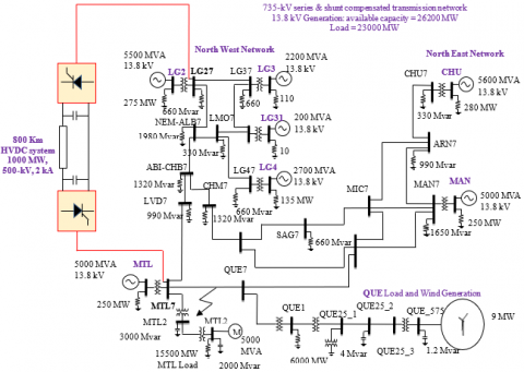
In this study the same system is used to study the transient stability which is a 29 Bus 735 kV transmission power system with seven 13.8 kV power generators with power system stabilizers PSS (total available generation =26200 MVA) counting hydraulic turbines. The 735 kV transmission power system is both shunt and series compensated using constant inductors and capacitors. The load is regrouped at two nodes (MTL7 and QUE7). The MTL Load subsystem is linked to the MTL7 node and contains four categories of load blocks linked to the 25 kV distribution system with two transformers: 230 kV/ 25 kV and 735 kV /230 kV [3].
The QUE Load and Wind Farm subsystem use a 6000 MW load (constant impedance Z and constant power PQ) coupled on the 120 kV node. A 9 MW wind farm model based on doubly fed induction generator is coupled to the 120 kV node with a 25-kV feeder and a 25 kV/120 KV transformer.
5.2 DC system
The 800 Km LCC-HVDC system is equipped between bus MTL7 and bus LG27 as shown in Figure 4.
The DC system is made up of a DC transmission line with lumped losses and diffused parameter line blocks. This model is based on the traveling wave method developed by Bergeron.
The Table 1 shows the HVDC link characteristics [3].
Table 1. DC link Data
|
|
Rectifier |
Inverter |
|
Bus |
MTL7 |
LG27 |
|
Commutation reactance |
0.01Ω |
0.11Ω |
|
Minimum control angle |
αmin=14° |
γmin=20° |
|
Transformer regulation range |
0.93 p.u. |
0.91p.u. |
|
DC line resistance |
12+2x0.3 |
|
|
Inverter rated DC power |
1000 MW |
|
|
Inverter rated DC voltage |
500 kV |
|
5.3 Control systems
The main aim of the HVDC control system is consistent power transmission which provides highly effective and adjustable energy flow that reacts to unexpected variations in load and thus improving the power system stability [3].
A voltage regulator and a current regulator work in parallel to control the converters and calculate firing pulses. The two regulators fall within the integral and proportional categories (PI controller).
In normal operation, the inverter regulates the voltage at the $V^*$ reference value while the rectifier regulates the current at the Idref reference value. control system employs Constant Current Control (CCC) method [34, 40-43]. The reference to current limit is obtained from the inverter side. This is done to guarantee the safety of the converter in circumstances when inverter side does not have an adequate dc voltage provision (due to a disturbance) or does not have the adequate load condition (load rejection) [41, 44].
In normal operation, the converter station operating as rectifier controls the current at the $I_{d c}^*$ reference value while the other converter station operating as inverter controls the voltage at the $V_{d c}^*$ reference value. The Vmg and Img parameters are respectively 0.05 p.u. and 0.1 p.u [3, 34].
Figure 4. System under study
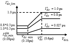
5.3.1 The VDCOL function
In order to maintain HVDC system in good condition and avoid commutation failure during disturbance, in the rectifier and inverter, a significant control technique is applied to vary the reference current with respect to the DC voltage value. When $V_{d c L}$ (Line DC voltage) declines, this control, Voltage Dependent Current Order Limits (VDCOL), instantly lowers the reference current ($I_{d c}^*$) set point (for instance, in the case of a DC line short-circuit or a severe AC short-circuit). Similarly, decreasing the $I_{d c}^*$ reference currents reduce the reactive power required on the AC network, assisting in the recovery from perturbations [34, 40, 41]. The VDCOL characteristics of the discrete 12-Pulse HVDC control are depicted in Figure 5. The $I_{d c}^*$ value begins reducing as soon as the $V_{d c L}$ line voltage decrease under a threshold value $V_{d r}^{t r}$ (0.6 p.u.). The actual reference current is called $I_{d c_{-} \lim}^*$. $I_{d c_{-} m i n}^{a b s}$ is the bare minimum $I_{d c_{-} s e t}^*$ at 0.08 p.u. When the DC line voltage decrease under the $V_{d c}^{t r}$ value, the VDCOL decreases immediately $I_{d c}^*$. However, VDCOL limits the $I_{d c}^*$ rise time with a time constant determined by parameter ($T_{u p}$) when the DC voltage recovers.
(a) Steady-state characteristics
(b) Dynamic characteristics
Figure 5. The VDCOL characteristics
The actions of VDCOL function are:
On the A phase of the line connecting the MTL7 and QUE7 buses, a severe single phase to ground short circuit fault was applied. Duration of the fault was 3 cycles. The results of this study are shown in Figure 6.
Figure 6. HVDC link response after fault
Once this short-circuit is applied at t = 4.5 s, it leads the DC voltage to drop and the DC current to rise to 3 kA before the current controller action decrease it. The rectifier switches to inverter mode of operation as the rectifier current controller attempts to reduce the current by increasing its firing angle. The DC current decreases to a low average value as regulated by VDCOL. When the short-circuit is removed at t = 4.56 s, the VDCOL function activates and increases the reference current to 2 kA. The system stabilizes around 0.56 s after short-circuit elimination.
Throughout the severe single-phase short-circuit at station 1 at t = 4.5s, during the short-circuit, the AC voltage at the rectifier side (MTL7) is slightly reduced, but it quickly and successfully returns to 1.0 pu voltage after the short-circuit is removed. Transmission power flow is reduced to a very low value during the short-circuit and returns to 1.0 pu following it. Recovering the steady state takes about 1 s. The DC voltage, which may be adjusted to 1.0 pu during the short-circuit, has few fluctuations at the beginning and the end of the short-circuit.
From Figure 7, it has been observed that with introducing HVDC link under the fault conditions. The voltage distortion on the inverter and rectifier side is significantly lower with an HVDC connection, and the time required to clear a fault is reduced to a minimum, the system is capable of getting normal mode of operation faster.
Figure 7. Voltage distortion at both inverter and rectifier sides
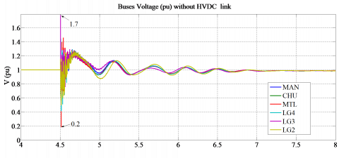
(a) Without HVDC link
(b) With HVDC link
Figure 8. Buses voltage during fault
As can be seen in Figure 8, when the fault is applied, there is overshooting in the voltage of all buses especially the LG3 bus of magnitude 1.7 pu and undershoot in the bus of MTL of magnitude of 0.2 pu. The system recovers in approximately 2s after fault clearing.
In the case after integrating HVDC Link the peaks of each voltage bus decrease more effectively and settle down faster to the steady state especially MTL and LG3 buses where the HVDC link is inserted and the system recovers in approximately 1s after fault clearing.
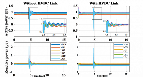
Figure 9. Active and reactive powers of generators
According to Figure 9, at the beginning of the short-circuit, the peak of the active and reactive power of the generators is larger and the amplitude of the oscillation as well as the stabilization time is longer in the case of a pure HVAC system (without HVDC link), while these oscillations decrease relatively faster in the case of an AC / DC system (with HVDC link).
Figure 10. Rotor speed and rotor speed deviations of generators
Figure 10 shows that the machines are out of phase when the fault starts and that the rotor speeds and rotor speed deviations continue to oscillate until the fault is cleared. The presence of an HVDC link significantly enhances the system response.
Figure 11. Rotor angles deviations of generators
Figure 12. Wind rotor speed
It can be seen that the magnitudes without HVDC link are much larger and higher than the contribution of HVDC link, in such a way that the rotor speed is reduced around 1 pu and rotor speed deviation reduced around zero faster in the presence of an HVDC link than in the pure HVAC system. The dynamic performance observed come to the conclusion that addition of HVDC link provided significant stabilization of rotor speed and rotor speed deviation.
Figure 11 shows clearly that during the fault the pure HVAC system becomes oscillatory unstable, rotor angle deviations are increased and the system continues losing synchronism. The magnitudes of rotor angles deviations without HVDC link are much larger and higher than the contribution of HVDC link. Besides, the effectiveness of a single HVDC link on wind power generation as a source of renewable energy during the fault, it can be seen that without HVDC link the maximum value of wind rotor speed is approximately 1.014 pu and the distortion is much larger, however, with HVDC link the maximum value is reduced below the 1.01 pu value and the distortion margin seems to converge quickly to 1.002 pu as shown in Figure 12.
As a result, there are significant differences with the installation of HVDC link to restrain stability of rotor angles deviations of generators and wind power generation.
A performance analysis of a multi-machine electric power transmission network instability phenomenon under contingency conditions are carried out. Once a phase to ground short-circuit happens in the AC system, the system becomes unstable owing to the continuous variation of rotor angles. The system stays unstable till the disturbance is removed.
From the simulation results obtained after the insertion of HVDC link, it is observed that the HVDC link provided significant stabilization of the various components of a power system during the fault and after a brief duration of time, the system recovers stability compared to the case of pure HVAC system.
In terms of power system stability, it has been determined that deploying an HVDC link in parallel with an HVAC transmission system provides a faster and more controllable response to system faults, hence improving the system's strength and stability.
|
HVAC |
High Voltage Alternating Current |
|
HVDC |
High Voltage Direct Current |
|
AC |
Alternating Current |
|
DC |
Direct Current |
|
FACTS |
Flexible Alternating Current transmission systems |
|
EG |
Embedded generations |
|
VSC LCC |
Voltage source converter Line commutated converter |
|
EMT |
Electromagnetic Transient |
|
VDCOL |
Voltage Dependent Current Order Limits |
|
PSS |
Power system stabilizers |
|
DFIG |
Doubly fed induction generator |
|
PI |
proportional and integral |
|
CCC |
Constant Current Control |
|
P |
Active power |
|
Q |
Reactive power |
|
I |
Current |
|
V |
Voltage |
|
pu |
Per unit |
|
Subscripts |
|
|
min |
minimum |
|
set |
Reference setpoint |
|
lim |
Reference limit |
[1] Toledo, P.F., Asplund, G., Jansson, E. (2004). Aspects on infeed of multiple HVDC into one AC network. ABB Power System, HVDC division, Ludvika, Sweden.
[2] Kamble, S.P., Kanojiya, S., Male, Y., Ingale, Gaurav., Manekar, P., Patrik, R., Shrikhande, R., Kamdi, S. (2017). Transient stability analysis of the IEEE 9-bus electric power system. International Journal of Engineering and Computer Science, 6(4). https://doi.org/10.18535/ijecs/v6i4.08
[3] Djehaf, M.A., Ahmed, Z.S., Youcef Islam, D.K. (2014). AC versus DC link comparison based on power flow analysis of a multimachine power system. Leonardo Electronic Journal of Practices and Technologies, 1(24): 49-61.
[4] Kundur, P., Paserba, J., Ajjarapu, V., et al. (2004). Definition and classification of power system stability IEEE/CIGRE joint task force on stability terms and definitions. In IEEE Transactions on Power Systems, 19(3): 1387-1401. https://doi.org/10.1109/TPWRS.2004.825981
[5] Kundur, P. (1994). Power System Stability and Control. New York: McGraw-Hill.
[6] Shahzad, U. (2022). Prediction of probabilistic transient stability using support vector regression. Australian Journal of Electrical and Electronics Engineering. https://doi.org/10.1080/1448837X.2022.2112302
[7] Cutsem, T., Vournas, C. (1998). Voltage Stability of Electric Power Systems. Norwell, MA: Kluwer.
[8] Azimoh, L.C., Folly, K.A., Chowdhury, S.P. (2009). Mitigations of voltage instability in power systems. 2009 IEEE Electrical Power & Energy Conference (EPEC), pp. 1-6. https://doi.org/10.1109/EPEC.2009.5420942
[9] Oni, O.E., Davidson, I.E., Parus, N. (2016). Static voltage stability analysis of Eskom eastern grid. 2016 IEEE International Conference on Renewable Energy Research and Applications (ICRERA), pp. 413-419. https://doi.org/10.1109/ICRERA.2016.7884371
[10] Hossain, M.J., Pota, H.R., Ugrinovskii, V. (2008). Short and long-term dynamic voltage Instability. IFAC Proceedings Volumes, 41(2): 9392-9397. https://doi.org/10.3182/20080706-5-KR-1001.01587
[11] Taylor, C.W. (1994). Power System Voltage Stability. McGraw-Hill.
[12] Biswal, S.S., Swain, D.R., Rout, P.K. (2022). Inter-area and intra-area oscillation damping for UPFC in a multi-machine power system based on tuned fractional PI controllers. Int. J. Dynam. Control, 10: 1594-1612. https://doi.org/10.1007/s40435-021-00891-4
[13] Dasu, B., Sivakumar, M., Srinivasarao, R. (2019). Interconnected multi-machine power system stabilizer design using whale optimization algorithm. Prot Control Mod Power Syst, 4(2). https://doi.org/10.1186/s41601-019-0116-6
[14] Hou J., Gao, S. (2021). Static and transient stability analysis of power system containing wind farms. IEEE Sustainable Power and Energy Conference (iSPEC), pp. 303-309. https://10.1109/iSPEC53008.2021.9735740
[15] Ainsworth, J.D., Gavrilovic, A., Thanawala, H.L. (1980). Static and synchrounous compensators for HVDC transmission convertors connected to weak AC systems, 28th Session CIGRE, 28(2): 1-11.
[16] CIGRE Working Group. (1992). Guide for Planning DC Links Terminating at AC Systems Locations Having Low Short-Circuit Capacities Part I: AC/DC Interaction Phenomena, CIGRE Guide No. 95.
[17] Barbier, C., Carpentier, L., Saccomanno, F. (1978). CIGRE SC32 Report: Tentative classification and terminologies relating to stability problems of power systems. ELECTRA, 56.
[18] IEEE TF Report. (1982). Proposed terms and definitions for power system stability. IEEE Transactions Power Apparatus and Systems, PAS-101(7): 1894-1897. https://doi.org/10.1109/TPAS.1982.317476
[19] Venkata, S.S., Eremia, M., Toma, L. (2013). Background of power system stability. In Handbook of Electrical Power System Dynamics (eds M. Eremia and M. Shahidehpour). https://doi.org/10.1002/9781118516072.ch8
[20] Wang, S. (2022). Adaptive quantization control for multi-machine power system with SVC and unknown disturbance. 2022 IEEE International Conference on Electrical Engineering, Big Data and Algorithms (EEBDA), pp. 159-163. https://doi.org/EEBDA53927.2022.9744871
[21] Saleem, B., Badar, R., Manzoor, A., Judge, M.A., Boudjadar, J., Islam, S.U. (2022). Fully Adaptive Recurrent Neuro-Fuzzy Control for Power System Stability Enhancement in Multi Machine System. In IEEE Access, 10: 36464-36476. https://doi.org/10.1109/ACCESS.2022.3164455
[22] Elliott, R.T., Choi, H., Trudnowski, D.J., Nguyen, T. (2022). Real power modulation strategies for transient stability control. In IEEE Access, 10. https://doi.org/10.1109/ACCESS.2022.3163736
[23] Hou J., Gao, S. (2021). Static and transient stability analysis of power system containing wind farms. IEEE Sustainable Power and Energy Conference (iSPEC), pp. 303-309. https://doi.org/10.1109/iSPEC53008.2021.9735740
[24] Yogarathinam, A., Kaur, J., Chaudhuri, N.R. (2017). Impact of inertia and effective short circuit ratio on control of frequency in weak grids interfacing LCC-HVDC and DFIG-Based wind farms. In IEEE Transactions on Power Delivery, 32(4): 2040-2051. https://doi.org/10.1109/TPWRD.2016.2607205
[25] To, K.W.V., David, A.K., Hammad, A.E. (1994). A robust co-ordinated control scheme for HVDC transmission with parallel AC systems. In IEEE Transactions on Power Delivery, 9(3): 1710-1716. https://doi.org/10.1109/61.311190
[26] Phulpin, Y., Hazra, J., Ernst, D. (2011). Model predictive control of HVDC power flow to improve transient stability in power systems. 2011 IEEE International Conference on Smart Grid Communications (SmartGridComm), pp. 593-598. https://doi.org/10.1109/SmartGridComm.2011.6102391
[27] Basu, K.P. (2009). Stability enhancement of power system by controlling HVDC power flow through the same AC transmission line. 2009 IEEE Symposium on Industrial Electronics & Applications, pp. 663-668. https://doi.org/10.1109/ISIEA.2009.5356370
[28] Mbangula, K.N.I., Davidson, I.E., Tiako, R. (2015). Improving power system stability of South Africa’s HVAC network using strategic placement of HVDC Links. Proceedings of the CIGRE International Symposium 2015 Development of Electricity Infrastructures for Sub-Saharan Africa, Cape Town, South Africa, pp. 26-30.
[29] Nguyen, M.H., Saha, T.K., Eghbal, M. (2010). A comparative study of voltage stability for long distance HVAC and HVDC interconnections. IEEE PES General Meeting, pp. 1-8, https://doi.org/10.1109/PES.2010.5589456
[30] Li. X.N., Liu. Y., Li. Tao., Chen. S.Y., Lei, X. and Lin, S.B. (2014). Study on the impact of commutation failure on AC voltage of rectifier-side in UHVDC. 2014 International Conference on Power System Technology, pp. 2154-2161. https://doi.org/10.1109/POWERCON.2014.6993623
[31] Shao Y., Tang, Y. (2010). Voltage stability analysis of multi-infeed HVDC systems using small-signal stability assessment. IEEE PES T&D, pp. 1-6. https://doi.org/10.1109/TDC.2010.5484473
[32] Tada, K., Umemura, A., Takahashi, R., Tamura, J., Matsumura, Y., Yamaguchi, D., Kudo, H., Niiyama, M., Taki, Y. (2018). Frequency control of power system with wind farms by using output frequency band control of HVDC interconnection line. 2018 53rd International Universities Power Engineering Conference (UPEC), pp. 1-6. https://doi.org/10.1109/UPEC.2018.8541850
[33] Jahan, E., Hazari, M.R., Rosyadi, M., Umemura, A., Takahashi, R., Tamura, J. (2017). Simplified model of HVDC transmission system connecting offshore wind farm to onshore grid. 2017 IEEE Manchester PowerTech, pp. 1-6. https://doi.org/10.1109/PTC.2017.7981049
[34] Khatir, M., Zidi, S.A., Fellah, M.K., Hadjeri, S., Dahou, O. (2006). HVDC transmission line models for steady-state and transients analysis in SIMULINK Environment. IECON 2006 - 32nd Annual Conference on IEEE Industrial Electronics, Paris, France, pp. 436-441. https://doi.org/10.1109/IECON.2006.347234
[35] Xiao, H., Sun, K., Pan, J., Liu, Y. (2020). Operation and control of hybrid HVDC system with LCC and full-bridge MMC connected in parallel. IET Generation, Transmission & Distribution, 14: 1344-1352. https://doi.org/10.1049/iet-gtd.2019.1336
[36] Hammad, A.E. (1999). Stability and control of HVDC and AC transmissions in parallel. Power Delivery, in IEEE Transactions on Power Delivery, 14(4): 1545-1554. https://doi.org/10.1109/61.796252
[37] Oyedokun, D.T., Folly, K.A., Chowdhury, S.P. (2009). Effect of converter dc fault on the transient stability of a multi-machine power system with HVDC transmission lines. IEEE AFRICON, Nairobi Kenya, https://doi.org/10.1109/AFRCON.2009.5308120
[38] Djilani kobibi Y.I., Samir, H., Ahmed, Z.S., DJEHAF, M.A. (2013). Modelling a unified power flow controller for the study of power system steady state and dynamic characteristics. In 5th International Conference on Modeling, Simulation and Applied Optimization (ICMSAO) IEEE, pp. 1-6. https://doi.org/10.1109/ICMSAO.2013.6552627
[39] Wu, F. (2018). Technical considerations for power grid interconnection in Northeast Asia. University of Hong Kong and California at Berkely.
[40] Povh, D., Retzmann, D., Kerin, E.T.U., Mihalic, R. (2006). Advantages of Large AC/DC System Interconnections, Report B4-304, CIGRE Session 2006, Paris.
[41] Jogendranath, M.S., Pavan Kumar, G. (2012). Power flow control in HVDC link using PI and ANN controllers. International Journal of Engineering Research and Development, 4(9): 52-58.
[42] Adepoju, G.A., Komolafe, O.A., Aborisade, D.O. (2011). Power flow analysis of the Nigerian transmission system incorporating facts controllers. International Journal of Applied Science and Technology, 1: 5.
[43] Lee, S.H., Chu, C.C. (2005). A web-based power flow calculation of large-scale power systems embedded with VSC-based HVDC systems. IEEE/PES Transmission and Distribution Conference & Exhibition: Asia and Pacific Dalian, China. https://doi.org/10.1109/TDC.2005.1547123
[44] Nayak, N., Mahali, M.S., Majumder, I., Jena, R.K. Dynamic stability improvement of VSC-HVDC connected multi machine power system by spider monkey optimization based PI controller. 2016 International Conference on Electrical, Electronics, and Optimization Techniques (ICEEOT), pp. 152-157. https://doi.org/10.1109/ICEEOT.2016.7754916