Yuan Zhang | Yougang Sun* | Zhouguo Hu | Baifu Fang | Ying Xie | Linkai Chen | Yuanyuan Teng
© 2022 IIETA. This article is published by IIETA and is licensed under the CC BY 4.0 license (http://creativecommons.org/licenses/by/4.0/).
OPEN ACCESS
With the depletion of land resources, demands for marine resources mining is increasing, the mining vessels which is known as one of the most important offshore equipment are widely concerned. The motions of wave surges in the marine environment will affect the operation of mining vessels, especially for the heave motion which will cause serious disturbances to the mining vessels during operation, and even the damage of the hull structure and related mining facilities. Hence, it is very necessary to compensate for the heave motion of the mining vessel, and a hydraulic cylinder-based active-passive integrated composite heave compensation system is designed in this paper. Firstly, the structural composition and working principle of the heave compensation system are introduced, and its mathematical model is also established. Secondly, the frequency domain and time domain analysis are carried out using AQWA software to obtain the heave displacement response of the ship under regular and irregular waves of six sea states as the desired compensation displacement. Finally, the controller of the active-passive heave compensation system is designed, and a fuzzy logic control strategy based on Mamdani type is proposed, and the control performance is analyzed. The results show that the accuracy of the fuzzy logic control algorithm is better than the traditional PID control algorithm, and the laws and methods of PID adjustment are obtained, which proves that the fuzzy logic control algorithm has obvious advantages for engineering applications.
mining vessel, heave compensation, PID control, fuzzy logic, heave displacement response of the vessel
Deep-sea mining vessels operate on the surface of the sea with a heave motion due to wave surges, which seriously affects the safety of the vessel and the mining system. In order to ensure the safe operation of the deep-sea mining vessel, it is necessary to compensate for the heave movement [1-5]. Currently heave compensation systems can generally be divided into passive system and active system. The passive heave compensation system has a simple structure and poor compensation accuracy, while the active heave compensation system has a complex structure, high energy consumption and good compensation accuracy. Thijs Eijkhout and Jovana Jovanova [6] applied the active heave compensation system on a floating crane for better installation and maintenance of offshore power plants, combining MPC and PID for more accurate control. Philipp et al. [7] also utilized the heave compensation system for more stable manipulation of crane stability. Mihail et al. [8] also used AMEsim for a simple simulation of the heave compensation system. And in order to better simulate the real wave conditions, Wang et al. [9] designed and studied the experimental platform for the heave compensation system. Duan [10] analyzed and studied the active heave compensation and anti-swing control system for offshore lifting. But most of these scholars' researches on the heave compensation system were on mechanical innovations, and few of them were from the perspective of control algorithms. And some control algorithm improvement can also play a good effect for machinery, for example, Li et al. [11] took fuzzy PID algorithm to study the anti-swing of overhead cranes. Tong et al. [12] analyzed and studied the ship-shore parallel system using fuzzy-internal mode double-loop control algorithm. Therefore, this paper analyzes the advantages and disadvantages of the current mainstream heave compensation system and proposes an active-passive composite heave compensation system that combines the advantages of both. Then this paper designs a fuzzy control algorithm for control from the perspective of the control algorithm. And this paper finally simulates active-passive composite heave compensation system in Simulink and compares the simulation results of the fuzzy control algorithm with those of the traditional PID control algorithm to verify the proposed system and algorithm [13].
2.1 Structural components of the heave compensation system
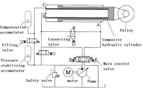
This study adopts the heave compensation system which is the active-passive composite type the main components of the compensation system include hydraulic station, winch, hydraulic cylinder, accumulator group, etc. The system structure sketch of the heave compensation system is shown in Figure 1.
Figure 1. Structure diagram of active and passive compound heave compensation system
2.2 The working principle of the heave compensation system
This study adopts the active-passive composite heave compensation system for the shortcomings of the passive compensation system with low accuracy and the active compensation system with excessive energy consumption. Under different working conditions, the passive compensation function can be switched with the active compensation function, which has broader load applicability. The hydraulic principal sketch is shown in Figure 2.
In the passive compensation mode, the proportional valve and the passive chamber filling valve are closed. The connecting valve is opened. The active chambers A and B are connected. The passive chamber C is connected to the passive chamber accumulator, and the flexible accumulator absorbs the lifting and sinking motion. Generally, the passive mode and active mode work simultaneously, but the system mainly works in the active mode [14]. At this time, the connecting valve and the passive chamber filling valve are closed, and the proportional valve compensates the hydraulic cylinder motion according to the collected lift and sink motion signal in closed loop control, which can significantly offset the lift and sink motion. At this time, the passive chamber is connected to the accumulator to balance the weight, which can reduce the energy consumption of the active control system [15].
Figure 2. Working principle of active-passive heave compensation system
Under the action of wind and wave current load, the ship hull will produce motion in six degrees of freedom, and the trajectory curve of the ship motion is related to the size of the ship. In this thesis, the displacement curve of the ship needs to be analyzed and calculated according to the size of the ship [16]. Taking the heave motion direction of the ship as an example, the heave displacement of the ship can be calculated by the pendular motion amplitude function of wave frequency, and the approximate expression of the pendular motion amplitude function of wave frequency is described as follows:
Heave $_{R A O}=\frac{\theta_{X}}{\xi_{a}}=D A F_{\text {Heave }} \frac{\omega^{2}}{g} 57.3 \sin \beta$ (1)
where, $\theta_{X}$ denotes the amplitude of the vessel's heave motion; $\xi_{a}$ denotes the incident wave amplitude, here the regular wave unit wave amplitude; $D A F_{\text {Heave }}$ denotes the power amplification factor obtained from the equation of heave motion; $\omega$ denotes incident wave circle frequency; $\beta$ denotes the incident wave angle [16].
For a given irregular wave spectrum as $S(\omega)$, the wave-frequency motion $S_{R}(\omega)$ response spectrum of the ship at zero speed is expressed as follows:
$S_{R}(\omega)=R A O^{2} S(\omega)$ (2)
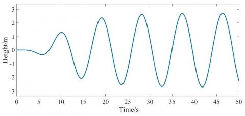
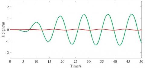
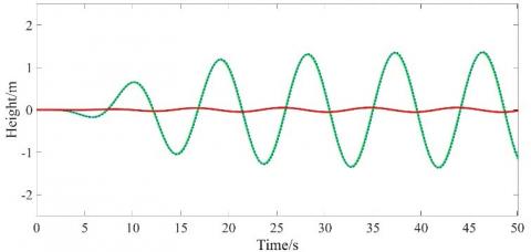
Then choose to carry out the calculation of mining ship displacement curve under the common six-level sea state in China, with wave height 5m and period 10 seconds, and use AQWA software to carry out frequency domain and time domain analysis, and get the ship's heave displacement curve under the six-level sea state as shown in Figure 3 and Figure 4 [17].
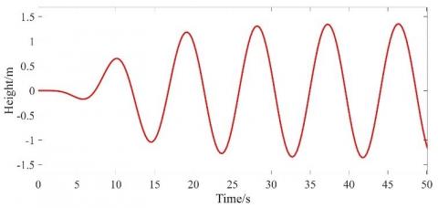
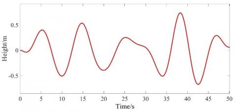
However, since the hydraulic cylinder and the weight are connected by a steel cable link and a dynamic pulley, it is possible to change the direction of the applied force and at the same time reduce the stroke of the hydraulic cylinder by half [18]. Therefore, for the proposed heave compensation hydraulic system, the displacement to be compensated is half of the displacement of the real wave weight, so the desired displacement of the compensation system designed in this project is half of all the above displacement curves, and the desired displacement curves shown in Figure 5 and Figure 6 are obtained [19].
Figure 3. Heave displacement curves of regular wave vessels in class VI sea state
Figure 4. Heave displacement curves of irregular wave vessels in class VI sea state
Figure 5. Expected displacement curves of regular wave vessels in class VI sea state
Figure 6. Expected displacement curves of irregular wave vessels in class VI sea state
The components of the heave compensation system include proportional valves, composite hydraulic cylinders, piston accumulators. Therefore, the model of each of its components should be modeled mathematically and the intermediate transfer function should be derived. Finally, the total transfer function can be derived [20].
4.1 Proportional valve model
Since there are many components of a proportional valve, it is difficult to know the various parameters and build an accurate mathematical model. In practical applications, the spool motion needs to be simplified to a first-order system with the transfer function can be written as
$G_{X U}(s)=\frac{K_{X U}}{T_{X U} s+1}$ (3)
where, $T_{X U}$ denotes time constant of valve spool movement; $K_{X U}$ denotes valve spool displacement-voltage gain coefficient.
4.2 Composite hydraulic cylinder model
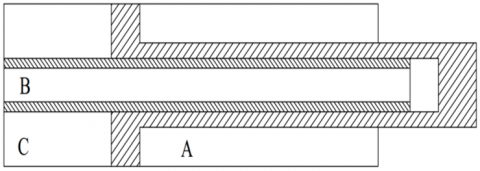
In this paper, the heave compensation system adopts the composite hydraulic cylinder structure, and its structure is shown in Figure 7. The composite design integrates the active and passive hydraulic cylinders together, which greatly saves the equipment space while realizing the active and passive combination [21].
Figure 7. Compound hydraulic cylinder structure
According to Newton's second law, the wire rope tension and weight force equilibrium equation as shown in Eq. (4).
$F_{m 1}=G-F_{b}+M \frac{d^{2} x_{L}}{d t^{2}}$ (4)
Under the action of active lifting and sinking compensation, the force balance equation of the hydraulic cylinder is can be expressed as follows
$A_{c} p_{c}+A_{p} p_{L}=M_{t} \frac{d^{2} x_{p}}{d t^{2}}+B_{p} \frac{d x_{p}}{d t}+K x_{p}+2 F_{m 1}$ (5)
The hydraulic cylinder active compensation chamber flow continuity equation is obtained as follows
$q_{L}=A_{c} \frac{d x_{p}}{d t}+\frac{V_{c}}{4 \beta_{e}} \frac{d p_{L}}{d t}+C_{e p} p_{L}$ (6)
4.3 Piston accumulator model
The piston accumulator uses a floating piston to isolate the liquid from the gas, and is used in combination with a gas cylinder. It can ensure the relative stability of hydraulic oil output pressure under the working condition of large flow and large volume.
The force balance equation of piston of piston accumulator is expressed as follows
$\left(p_{c}-p_{g}\right) A_{g}=m \frac{d^{2} x_{g}}{d t^{2}}+B_{g} \frac{d x_{g}}{d t}+K_{g} x_{g}+F_{f g}$ (7)
4.4 Model of active-passive lifting heave compensation system
The hydraulic cylinder active compensation chamber flow continuity equation is obtained as:
$q_{L}=A_{c} \frac{d x_{p}}{d t}+\frac{V_{c}}{4 \beta_{e}} \frac{d p_{L}}{d t}+C_{e p} p_{L}$ (8)
Under the action of heave compensation, the hydraulic cylinder force balance equation is rewritten as:
$A_{c} p_{c}=M_{t} \frac{d^{2} x_{p}}{d t^{2}}+B_{p} \frac{d x_{p}}{d t}+K x_{p}+2\left[G-F_{b}+M \frac{d^{2}\left(2 x_{p}\right)}{d t^{2}}+F_{z z}\right]$ (9)
Therefore, in the active-passive compensation mode, the transfer function of the hydraulic cylinder rod displacement resulting from the displacement of the proportional valve spool is obtained as follows:
$\frac{X_{\mathrm{p}}}{X_{\mathrm{sv}}}=\frac{\frac{A\quad_{\mathrm{c}}^{2} K_{\mathrm{g}}}{A\quad_{\mathrm{p}} A_{\mathrm{g}}^{2}}\left[\frac{m V_{\mathrm{t}}}{4 \beta\quad_{\mathrm{e}} A\quad_{\mathrm{p}}^{2}} s^{2}+\left(\frac{C\quad_{\mathrm{tp}} m}{A\quad_{\mathrm{p}}^{2}}+\frac{V_\quad{\mathrm{t}} B\quad_{\mathrm{g}}}{4 \beta_{\mathrm{e}} A\quad_{\mathrm{p}}^{2}}\right) s+\frac{2 K\quad_{\mathrm{g}} V_{\mathrm{t}}}{4 \beta\quad_{\mathrm{e}} A\quad_{\mathrm{p}}^{2}}+\frac{A_{\mathrm{g}}^{2}}{A\quad_{\mathrm{p}}^{2}}\right]}{\frac{\left(M\quad_{\mathrm{t}}+4 M\right) V\quad_{\mathrm{t}}}{4 \beta\quad_{\mathrm{e}} A\quad_{\mathrm{p}}^{2}} s^{3}+\left[\frac{\left(M\quad_{\mathrm{t}}+4 M\right) K\quad_{\mathrm{ce}}}{A\quad_{\mathrm{p}}^{2}}+\frac{V\quad_{\mathrm{t}} B\quad_{\mathrm{p}}}{4 \beta\quad_{\mathrm{e}} A\quad_{\mathrm{p}}^{2}}\right] s^{2}+\left(\frac{K\quad_{c e} B\quad_{p}}{A\quad_{p}^{2}}+\frac{K V\quad_{t}}{4 \beta\quad_{e} A\quad_{p}^{2}}+1\right) s+\frac{K K\quad_{c e}}{A_{p}^{2}}}$ (10)
Table 1. The meaning and values of parameters for heave compensation system
|
Name |
Meaning |
Name |
Meaning |
|
Time constant of valve spool movement |
0.025 |
Effective bulk modulus of elasticity/MPa |
700 |
|
Spool displacement-voltage gain coefficient |
0.0002 |
Total leakage coefficient of hydraulic cylinder/ m3·(s·pa)-1 |
2x10-12 |
|
Proportional valve damping ratio |
0.8 |
Equivalent load stiffness at the hydraulic cylinder rod |
2x10⁷ |
|
Proportional valve amplifier gain |
4 |
Equivalent mass at the hydraulic cylinder rod / t |
200 |
|
Proportional valve pilot stage gain |
4 |
Load mass/t |
200 |
|
Proportional valve inherent frequency/Hz |
80 |
Equivalent viscous damping coefficient/N·m-2 |
1639 |
|
Hydraulic cylinder C chamber action area/m2 |
0.158 |
Equivalent gas stiffness factor=Ka/ N/m |
2x10⁷ |
|
Accumulator Equivalent Stiffness/N/m |
2x10⁷ |
Accumulator gas chamber initial state coefficient |
0.06 |
|
Hydraulic cylinder active compensation chamber action area (m2) |
0.048 |
Vtc=V0c initial volume of passive compensation chamber/m3 |
0.474 |
|
Piston accumulator piston action area/ m2 |
0.342 |
Passive compensation cavity external leakage/m3·(s·pa)-1 |
2x10-12 |
|
Piston mass of accumulator/kg |
20 |
Effective bulk modulus of elasticity (MPa) |
700 |
|
Effective volume of hydraulic cylinder action/m2 |
0.762 |
|
|
In this system, in order to derive the specific transfer function, the value of each parameter needs to be determined. After reviewing the relevant literature and data, the meanings and values of all parameters are determined as shown in Table 1.
Since the active-passive composite compensation system is mainly studied for the active compensation system, the above data are substituted into the transfer function expression, that is, the transfer function of the system in active mode as shown in (11) is derived.
$G(S)=\frac{0.0002}{0.001 s^{2}+0.125 s+1} * \frac{8.9^{*}\left[2.3 \times 10^{-6} s^{2}+1.93 \times 10^{-4}+50\right]}{0.12 s^{3}+0.001064 s^{2}+1.0001422743 s+1.74 \times 10^{-9}}$ (11)
In the active-passive lifting and sinking compensation mode, a PID controller based on a fuzzy logic system needs to be designed for the active compensation mode of operation. The fuzzy logic control method (Fuzzy Logic Control) is suitable for relatively complex control systems where an accurate model is not currently available, and can improve the control accuracy of the system, so this method is widely used at present. In order to improve the robustness of the active compensation system, a fuzzy logic system can be used to design a controller without a model, which is characterized by parameter uncertainty, strong nonlinearity and hysteresis of the lift-sink compensation system. The design of the fuzzy logic system consists of two steps, which are presetting $K_{P}, K_{I}, K_{D}$ three parameter values and designing the collation fuzzy rules.
5.1 Presetting $K_{P}, K_{I}, K_{D}$ three parameter values
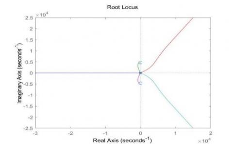
First, the root trajectory of the system is plotted using MATLAB and the root trajectory is schematically shown in Figure 6.
Figure 8. Root trajectory of system
From the schematic diagram of the root trajectory in Figure 8, it can be seen that a root trajectory exists on the imaginary axis, thus indicating that the system is critically stable, and the requirements for the parameters are relatively high. To make the use of the PID algorithm to control this transfer function and achieve stability, it is necessary to design a suitable PID controller, to determine the appropriate values of the three parameters$K_{P}, K_{I}, K_{D}$. Moreover, in the design of this heave compensation system, the system is required to achieve the following specifications: 0.1 unit step steady-state error, 10% overshoot, and 2 seconds of transition process time.
Therefore, the steady-state error constant after adding the PID controller can be derived from (12):
$\left.K_{I} G(s)\right|_{s=0}=\frac{1}{3.19} K_{I}=\frac{1}{0.1}=10$ (12)
According to $K_{I}=31.9$, the desired closed-loop damping coefficient and intrinsic frequency can be determined from the two technical specifications of overshoot and transition process as $\xi=0.6, \omega_{n}=4 \mathrm{rad} / \mathrm{s}$ respectively. Therefore, given $\omega_{g c}=4 \mathrm{rad} / \mathrm{s}, P_{m}=\arcsin 60=80^{\circ}$, the values of $K_{P}, K_{D}$ can be calculated initially by the program in MATLAB. Run the program and obtain the results: $K_{P}=198.343, K_{D}=11.3233$.
Therefore, in the simulation of this system, the PID controller$K_{P}, K_{I}, K_{D}$ need to be taken as 200, 30 and 10, respectively.
Since the control parameters of conventional PID control are given by calculation, the values of the three parameters $K_{P}, K_{I}, K_{D}$ obtained by calculation are not necessarily optimal because the waves vary irregularly. Therefore, in order to find better PID control parameters, it is necessary to design a control that can automatically adjust the parameters according to the change of sea conditions, so if the fuzzy PID controller is used to control the system. The parameters $K_{P}, K_{I}, K_{D}$ can be automatically adjusted according to the actual sea state fluctuations based on the preset parameters.
5.2 Fuzzy logic algorithm-based controller design
The design process of the PID controller based on fuzzy logic system is as follows: firstly, e is defined as the difference between the actual displacement and the desired displacement, and ec represents the rate of change of the difference between the actual displacement and the desired displacement with time. The rate of change of mis interpolation e and error ec is then detected by sensors and then transformed into the fuzzy domain by quantization factors Ke and Kec to obtain the increments $\Delta K_{p} / \Delta K_{i} / \Delta K_{d}$ of the three parameters to be PID controller [11].
The general principal expression of the fuzzy controller is shown in (13).
$G_{c(s)}=k_{p}+\frac{k_{i}}{s}+k_{d} \bullet s$ (13)
Finally, the three parameters are calculated to obtain the final input parameters to the PID controller as shown in (14).
$\left\{\begin{array}{c}k_{p}=k_{p 0}+\Delta k_{p} \\ k_{i}=k_{i 0}+\Delta k_{i} \\ k_{d}=k_{d 0}+\Delta k_{d}\end{array}\right.$ (14)
Substituting into (9), the final expression of the design of this lift-sink compensation fuzzy controller is obtained as follows
$G_{c(s)}=\left(k_{p 0}+\Delta k_{p}\right)+\frac{k_{i 0}+\Delta k_{i}}{s}+\left(k_{d 0}+\Delta k_{d}\right)$ (15)
According to the mining vessel operation characteristics and control experience, the proposed fuzzy rule table is shown in Table 2. Establishing fuzzy control rules is actually describing the control experience through fuzzy language [9]. The commonly used forms of fuzzy controllers are Mamdani type and T-S type. Compared to the T-S fuzzy logic system, the Mamdani type fuzzy rule output is a fuzzy quantity, which is similar to the natural human language information and easy to understand, so the Mamdani type controller is chosen [11].
6.1 Traditional PID control algorithm
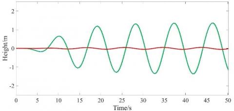
The conventional PID control algorithm [22-24] is used to control and simulated under six levels of regular and irregular waves of sea state respectively, and then the simulation result graph can be obtained as shown in Figure 9 and Figure 10.
In the Figure 9(a) and Figure 9(b), the green solid line A is the desired displacement of the heave compensation, the red dashed line B is the actual displacement of the heave compensation, and the blue solid line C is the difference between the actual displacement of the heave compensation and the desired displacement. According to the accuracy formula of the heave compensation system, the compensation accuracy of the regular and irregular waves under six sea states can be calculated as 94.54% and 94.98%, respectively, when the transfer function is controlled by the conventional PID algorithm [21].
Table 2. Fuzzy rules table
|
$\Delta K_{p} / \Delta K_{i} / \Delta K_{d}$ |
ec |
|||||||
|
NB |
NM |
NS |
ZO |
PS |
PM |
PB |
||
|
e |
NB |
PB/NB/PS |
PB/NB/PS |
PB/MB/ZO |
PM/NM/ZO |
PS/NM/NS |
PS/PM/ZO |
ZO/ZO/PB |
|
NM |
PB/NB/NS |
PB/NB/NS |
PB/NM/NS |
PS/NM/NS |
PS/NS/NS |
ZO/ZO/ZO |
ZO/ZO/NB |
|
|
NS |
PM/NM/NB |
PM/NM/NB |
PM/NS/NM |
PS/NS/NS |
ZO/ZO/NS |
NS/PS/ZO |
NM/PS/PS |
|
|
ZO |
PM/NM/NB |
PS/NS/NM |
PS/NS/NM |
ZO/ZO/NS |
NS/PS/ZO |
NM/PS/ZO |
NM/PM/PS |
|
|
PS |
PS/NS/NB |
NM/PS/NM |
ZO/ZO/NS |
NS/PS/NS |
NS/PS/PS |
NM/PM/ZO |
NM/PM/PS |
|
|
PM |
ZO/ZO/NM |
ZO/ZO/NS |
NS/PS/NS |
NM/PM/NS |
NM/PM/PS |
NM/PB/ZO |
NB/PB/PS |
|
|
PB |
ZO/ZO/PS |
NS/ZO/ZO |
NS/PS/ZO |
NM/PM/ZO |
NM/PB/PS |
NM/PB/ZO |
NM/PB/PM |
|
(a) Class VI sea state regular wave
(b) Class VI sea state irregular wave
Figure 9. Simulation result curve of traditional PID control algorithm under Class VI sea state regular wave
6.2 Fuzzy logic control algorithm
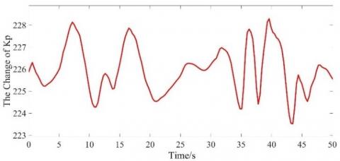
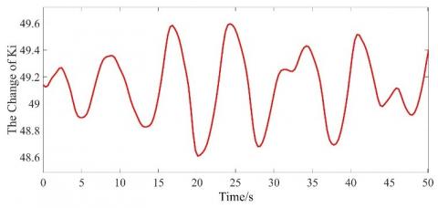
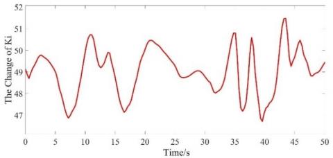
Using the fuzzy PID control algorithm for control, and placed under the six-level sea state regular wave and irregular wave respectively for simulation, can achieve the automatic regulation of $K_{P}, K_{I}, K_{D}$ and achieve the best accuracy, the change of schematic diagram is shown from Figure 11 to Figure 12.
The graph of simulation results shown in Figure 13 and Figure 14 can also be obtained.
(a) Class VI sea state regular wave
(b) Class VI sea state irregular wave
Figure 10. Variation range of $K_{p}$ under regular wave and irregular wave
(a) Class VI sea state regular wave
(b) Class VI sea state irregular wave
Figure 11. Variation range of $K_{p}$ under regular wave and irregular wave
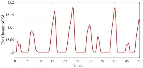
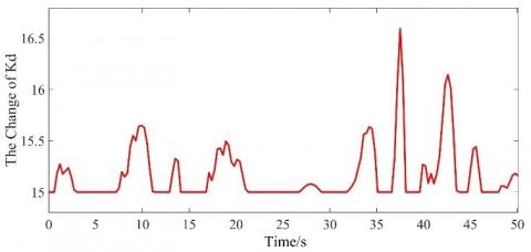
(a) Class VI sea state regular wave
(b) Variation range of $K_{d}$ under regular wave and irregular wave
Figure 12. Variation of $K_{P}, K_{I}, K_{D}$ under the regular ratio and irregular waves of the six sea states
In Figure 9, the green solid line A is the desired displacement of the heave compensation, the red dashed line B is the actual displacement of the heave compensation, and the blue solid line C is the difference between the actual and desired displacement of the heave compensation. According to the accuracy formula of the heave compensation system, it can be concluded that the compensation accuracy is 95.73% and 96.84% under the regular and irregular waves of the six-level sea state by using the fuzzy logic control algorithm to control the transfer function, respectively. And it can be seen from the simulation process that the fuzzy controller $K_{P}, K_{I}, K_{D}$ can have a range of variation in order to pursue the best compensation accuracy under each different kind of waves.
Figure 13. Simulation result curve of Fuzzy PID control algorithm under Class VI sea state regular wave
Figure 14. Simulation result curve of Fuzzy PID control algorithm under Class VI sea state irregular wave
In this paper, an active-passive composite heave compensation system is proposed for the longitudinal dynamic response problem caused by the heave motion of mining vessels. The system is analyzed from the perspective of control algorithm, and a fuzzy logic control algorithm is designed. The simulate and compare are carried out in Simulink under six levels of sea state regular sea wave and irregular sea wave. The simulation results of fuzzy logic control algorithm are compared with the algorithm simulation results of traditional PID control, and finally get the following conclusions.
(1) Under the six-level sea state rule wave, the compensation accuracy of traditional PID control is 94.54%; the compensation accuracy of fuzzy PID control is 95.73%, and the compensation accuracy of fuzzy control is 1.19% higher than that of traditional PID control.
(2) Under the six-level sea state irregular waves, the compensation accuracy of traditional PID control is 94.98%; the compensation accuracy of fuzzy PID control is 96.84%, and the compensation accuracy of fuzzy control is 1.86% higher than that of traditional PID control.
(3) The accuracy of the fuzzy control algorithm is better than that of the traditional PID control algorithm, especially under irregular waves, which can better reflect the advantages of the fuzzy control algorithm.
(4) For this heave compensation system, the designed fuzzy PID controller can be adjusted $K_{P}, K_{I}, K_{D}$ according to the different pairs of values of sea conditions, and after analysis, the best numbers can be known as 220, 45 and 5.
This work is supported by Shanghai Science and Technology Commission supported Project: Research on Compensation Technology of mining pipe heave motion (Grant numbers: 19DZ1207304).
[1] Woodacre, J.K., Bauer, R.J., Irani, R.A. (2015) A review of vertical motion heave compensation systems. Ocean Engineering, 104: 140-154. https://doi.org/10.1016/j.oceaneng.2015.05.004
[2] Yang, T., Sun, N., Chen, H., et al. (2019). Neural network-based adaptive anti swing control of an underactuated ship-mounted crane with roll motions and input dead zones. IEEE Transactions on Neural Networks and Learning Systems, 31(3): 901-914. https://doi.org/10.1109/TNNLS.2019.2910580
[3] Xu, Z., Wang, Z., Shen, Z., Sun, Y. (2021). Non-linear differential and integral sliding mode control for wave compensation system of ship-borne manipulator. Measurement and Control, 54(5-6): 711-723. https://doi.org/10.1177/0020294020944956
[4] Sun, Y., Qiang, H., Xu, J., et al. (2017). The nonlinear dynamics and anti-sway tracking control for offshore container crane on a mobile harbor. Journal of Marine Science and Technology, 25(6): 656-665. https://doi.org/10.6119/JMST-017-1226-05
[5] Tang, G., Lu, P., Hu, X., et al. (2021). Control system research in wave compensation based on particle swarm optimization. Scientific Reports, 11(1): 1-11. https://doi.org/10.1038/s41598-021-93973-4
[6] Eijkhout, T., Jovanova, J. (2021). Active heave compensation of a floating crane using electric drive. 2021 IEEE/ASME International Conference on Advanced Intelligent Mechatronics (AIM), 2021, pp. 1089-1094. https://doi.org/10.1109/AIM46487.2021.9517502
[7] Schubert, P., Stemmler, S., Abel, D. (2019). Towards predictive anti-sway control of hanging loads: model-based controller design for a knuckle boom crane. 18th European Control Conference (ECC), IEEE, Naples, Italy, pp 2276-2282. https://doi.org/10.23919/ECC.2019.8795871
[8] Petrache, M., Vasiliu, N., Calinoiu, C., et al. (2019). Design of the electrohydraulic heave compensation systems for marine cranes. 2019 International Conference on Energy and Environment (CIEM), IEEE, pp. 449-453. https://doi.org/10.1109/CIEM46456.2019.8937695
[9] Wang, Y., Du, H., Xu, C., et al. (2016). Design of experimental platform for lifting and sinking compensation system. Experimental Technology and Management, 38(1): 6.
[10] Duan, Y. (2021). Research on active lifting and sinking compensation and anti-swing control system for offshore lifting. Jiangsu University of Science and Technology.
[11] Li, F., Cao, X. (2021). Research on fuzzy PID anti-sway control method for overhead cranes. Crane and Transport Machinery, (18): 29-35.
[12] Tong, X.F., Hu, A., Liu, H.J., et al. (2021). A ship-shore grid-connected system based on fuzzy-internal-mode dual-loop control. Science Technology and Engineering, 21(34): 14561-14569.
[13] Sun, J.M., Liu, X., Zhao, G.H., Zhou, Q.H. (2021). Fuzzy feedback incremental proportional-integral differential oil and gas suspension control. Science Technology and Engineering, 21(34): 14814-14820.
[14] Lv, J., Sun, Y., Dong, D. (2020). Automatic positioning and anti-sway control of shore bridge based on virtual prototype, Science. Technology and Engineering, 20(03): 1092-1098.
[15] Sun, Y., Dong, D., Qiang, H., Teng, Y. (2018). Research on trolley position tracking and lifting weight dissipation control of offshore floating container crane. Vibration and Shock, 37(11): 207-215.
[16] Li, W. (2021). Research on electro-hydraulic control system for secondary regulation wave lift and sink compensation of offshore winches. Shandong University.
[17] Sun, Y., Li, W., Liu, X. (2016). Simulation and research of wave compensation system for offshore floating crane platform operation. Chinese Journal of Engineering Machinery, 14(03): 198-205.
[18] Wang, M. (2021). One-dimensional fuzzy PID controller design. Information Technology and Informatization, 3:71-72.
[19] Wu, W.Y., Liu, X.S., Guo, Z.F., Wang, H.S. (2021). Research on real-time control of time delay of active lift and sink compensation system for marine cranes. Hydraulics and Pneumatics, 45(04): 167-174.
[20] Ren, Z., Skjetne, R., Verma, A., Jiang, Z., Gao, Z., Halse, K. (2021). Active heave compensation of floating wind turbine installation using a catamaran construction vessel. Marine Structures, 75: 102868. https://doi.org/10.1016/j.marstruc.2020.102868
[21] Ku, N. (2021). Heave compensation dynamics for offshore drilling operation. Journal of Marine Science and Engineering, 9(9): 965. https://doi.org/10.3390/jmse9090965
[22] Khadkikar, V., Chandra, A., Singh, B.N. (2009). Generalized single-phase PQ theory for active power filtering: simulation and DSP-based experimental investigation. IET Power Electronics, 2(1): 67-78. https://doi.org/0.1049/iet-pel:20070375
[23] Euldji, R., Batel, N., Rebhi, R., Kaid, N., Tearnbucha, C., Sudsutad, W., Lorenzini, G., Ahmad, H., Ameur, H., Menni, Y. (2022). Optimal backstepping-FOPID controller design for wheeled mobile robot. Journal Européen des Systèmes Automatisés, 55(1): 97-107. https://doi.org/10.18280/jesa.550110
[24] Chilipi, R., Al Sayari, N., Al Hosani, K., Fasil, M. (2018). Third order sinusoidal integrator (TOSSI)-based control algorithm for shunt active power filter under distorted and unbalanced voltage conditions. International Journal of Electrical Power & Energy Systems, 96: 152-162. https://doi.org/10.1016/j.ijepes.2017.09.026