Fatima Merdj* | Said Drid
© 2022 IIETA. This article is published by IIETA and is licensed under the CC BY 4.0 license (http://creativecommons.org/licenses/by/4.0/).
OPEN ACCESS
The magnetohydrodynamic pump is an attractive solution, in particular for biomedical applications. In an MHD pump, an electromagnetic force is created by the applied magnetic field, which causes the fluid movement. The main advantage of the MHD pump is there are no mobile (mechanical) parts and it can place directly on veins. The present paper deals with the blood behaviour in the MHD micropump. A neodymium permanent magnet is used for applying a magnetic field to the channel in the MHD micropump. The numerical study examines the influence of the channel dimensions, the flux magnetic density and the electrode potentials on the blood velocity. This micropump can be easily controlled by a low voltage source. The numerical simulation analysis for the adopted model was implemented in order to verify the micropump operation. The magnetic and electrical fields have a strong influence on blood velocity in the MHD micropump. Finite element modelling software was used for this process. The second objective of this work is the possibility to exploit the properties of this pump in hemodialysis to pump blood and cleaning fluid.
biomedical microsystems, micropumps, magnetohydrodynamic (MHD), DC MHD, Lorentz force
The human body in its natural state, kidneys, these 2 small biological organs in the renal system represent a vital function.
By assisting the body in excreting waste as urine and filtering blood before returning it to the heart, they serve a variety of vital activities [1]. Kidneys that have been damaged lose their capacity to execute these functions, and there are a variety of treatments for chronic renal failure but dialysis is currently the only treatment available for this kind of patient in the absence of a transplant [2].
Hemodialysis is a method of cleansing blood outside the body that involves drawing blood from a vein and putting it through a synthetic filter called a dialyzer. The dialyzer is also known as an "artificial kidney" since it filters waste products, chemical substances, and fluids from the blood before returning it to the body. A dialysis machine governs the process by pumping blood across the circuit, adding dialysis, and regulating the cleansing process. Hemodialysis, which takes three to six hours on average and is done at least three times a week, is normally done in a medical centre [3]. New innovations are required in this field in order to develop an intelligent dialysis system that can analyse and understand changes in patient homeostasis and respond properly in real-time.
Technological advances are needed in machine size, efficiency, and robustness to ensure continuous patient monitoring and treatment optimization [4]. It is concerned with the creation of miniature devices capable of detecting, pumping, mixing, and controlling small quantities of fluids. Among the microfluidic systems are micro-pumps, which are an interesting device that provides the means to control and distribute small volumes of flow rates [5]. As a result, the micropump is an important part of drug delivery systems that produces the actuation mechanism to transfer with potential for impact over a wide field of research [6].
With the potential to impact a broad field of research, the main criteria for classifying them are their principle of operation, design, size, precise flow control, low energy consumption and compatibility with other microfluidic systems. The applications of these microfluidic devices are mainly in the biomedical field. In general, mechanical and non-mechanical micropumps are the two types of micropumps available. Micropumps that have mechanical parts in motion are designated as mechanical micropumps whereas those which do not have moving parts are called non-mechanical micropumps. MHD domain access to biomedical applications was noticed, especially in the blood flow study. When the human body is subjected to an MRI scanner, blood flow is considered as a conductor that is submitted into the magnetic field creating “Lorentz force” and inducing electrical voltages across vessel walls [7]. This attracts more attention in the most recent studies [8, 9].
The magnetic properties of blood allow being treated with an electromagnetic field. In comparison to conventional medical pumps, electromagnetic blood flow pumps have a more elegant and long-lasting technology [10].
The MHD pump with high output pressure, rapid response time and low power consumption are one of the actuation technologies that is often discussed due to its simplicity [11]. the fundamental working concept of such pumps is the study of the interaction between an electrical current and a perpendicular magnetic field passes through moving, conducting fluids [12], where the magnetic field has many effects on natural and artificial flows. As a result, the fluid ions are subjected to a Lorentz force [13]. This force causes a pressure difference in the flow cell that pumps the fluid flow.
The MHD pumps advantages are the absence of moving parts, simple fabrication processes, no risk of mechanical fatigue and continuous fluid flow [14]. A prototype of an MHD pump was realized in the LSPIE Lab at the University of Batna 2, Figure 1.
Figure 1. Laboratory setup
In the Figure 1 we can identify the channel which is made of PVC material with two electrodes, a magnetic circuit, a coil to vary the magnetic field and a flexible pipe to channel the liquid, as well as measuring devices (running and voltage) and two DC sources.
The main contribution of this work is the design and the optimization of the DC-MHD parameters to improve the efficiency the pumping of blood movement.
Inducing current in a moving conductive fluid in the presence of a magnetic field generates a force on the conductive fluid's electrons and also modifies the magnetic field itself, according to MHD theory [14].
The laminar flow models must be applied. The steady-state magnetohydrodynamic model's formulation has been defined by the Navier-Stokes equations, coupled with Electromagnetism, defined by Maxwell's equations.
In both flow models, a Newtonian incompressible fluid was considered [15].
$\left\{ \begin{align} & \nabla \cdot \mathbf{B}=0\begin{matrix} {} & {} & {} & {} & {} \\\end{matrix}(N{{o}_{{}}}magneti{{c}_{{}}}monopoles) \\ & \nabla \times \mathbf{E}=-\frac{\partial \mathbf{B}}{\partial t}\begin{matrix} {} & {} & {} & {} \\\end{matrix}(Farada{{y}_{{}}}law) \\ & \nabla \cdot \mathbf{E}=\frac{{{\rho }_{o}}}{{{\varepsilon }_{o}}}\begin{matrix} {} & {} & {} & {} & {} \\\end{matrix}(Gaus{{s}_{{}}}law) \\ & \nabla \times \mathbf{B}={{\mu }_{o}}\mathbf{J}+{{\mu }_{o}}{{\varepsilon }_{o}}\frac{\partial \mathbf{E}}{\partial t}\begin{matrix} {} & {} \\\end{matrix}(Amper{{e}_{{}}}law) \\\end{align} \right.$ (1)
$\nabla \cdot \mathbf{D}=\rho $ (2)
Steady Maxwell Equations:
$\nabla \cdot \mathbf{J}=0$ (3)
$\nabla \cdot \mathbf{E}=0$ (4)
where, B is the magnetic induction, E is the electric field, $\rho_{0}$ is the volume density and $\varepsilon_{0}$ is the permittivity of space, D is Electrical induction. By combining with Ohm's Law:
$\mathbf{J}=\sigma [\mathbf{E}+\mathbf{u}\times \mathbf{B}]$ (5)
Ohm's Low:
$\mathbf{J}=\sigma [-\nabla \Phi +\mathbf{u}\times \mathbf{B}]$ (6)
The electromagnetic part of the problem is presented by Maxwell-Ampere's law in Eq. (1), Ohm's law in Eq. (5) and the conservation of the electrical current in Eq. (6), u is the velocity of the fluid, J is the total current density, $\sigma$ is the electrical conductivity, $\boldsymbol{\mu}$ is the permeability. Here the electrical potential scalar $\Phi$ is determined by solving the Poisson equation:
$\nabla^{2} \Phi=\nabla \cdot(\mathbf{u} \times(\nabla \times \mathbf{A}))$ (7)
where, A is the magnetic potential vector. In such a situation where a current is allowed to flow across the medium, an additional force is present. this force is generated by the interaction between the external magnetic field and that of the conductor.
Lorentz force which is written:
${{\mathbf{F}}_{L}}=\mathbf{J}\times \mathbf{B}$ (8)
${{\mathbf{F}}_{L}}=\left( \frac{1}{{{\mu }_{0}}} \right)\left( \nabla \times \mathbf{B} \right)\times \mathbf{B}$ (9)
where, FL is the Lorentz force, J is the total current density, B is the magnetic induction and through the derivation of the behaviour of interacting magnetic fields, Maxwell's equations can then be applied to fluid flow and MHDs.
2.1 Application of Lorentz force to fluid flow
In this study of MHD micropump, a steady-state is considered, an incompressible laminar flow and the velocity of the fluid along the y and z axes also estimated to be nulls are chosen. Based upon the above assumption, the axial flow velocity (u) is invariant along the x-direction such that. On the other hand, the influence of surface tension is ignored because the microchannel is assumed to be filled with fluids.
For the simplified flow field, the governing equations can be written as follows:
Equations systems (10) and (11) represent respectively the continuity equation and Navier-Stokes equations which define the physics of the fluid flow [16].
$\nabla .\mathbf{u}=0$ (10)
$\rho \left( \mathbf{u}.\nabla \right)=-\nabla P+\mu {{\nabla }^{2}}\mathbf{u}+F$ (11)
Particulate interactions must be considered when blood flow in the human body is exposed to a magnetic field. The total electromagnetic force can also be represented as the sum of the Lorentz, magnetophoretic, and electrostatic forces, and these solutions are generally considered homogeneous and electrically neutral flow.
$F={{F}_{L}}+{{F}_{\nabla B}}+{{F}_{E}}$ (12)
In most clinical uses of the MHD effect, applied magnetic field is homogeneous and static, the magnetophoretic and electrostatic forces are also assumed to be zero in Eq. (12), then the only remaining force is the Lorentz force Eq. (9) to be replaced in the Navier-Stokes equation Eq. (13). This represents the flow of a conductive fluid when exposed to an external magnetic field.
$\rho \left( \frac{\partial \mathbf{u}}{\partial t}+\mathbf{u}.\nabla \mathbf{u} \right)=-\nabla P+\mu {{\nabla }^{2}}\mathbf{u}+\left( \frac{1}{{{\mu }_{0}}} \right)\left( \nabla \times \mathbf{B} \right)\times \mathbf{B}$ (13)
under electromagnetic interactions, the Lorentz forces affecting the fluid particles are assumed to be a hydrostatic pressure uniformly distributed over the entire channel region, it is written as follow:
$\frac{\Delta P}{L}=\frac{\partial P}{\partial x}$ (14)
In the MHD micropump, the Lorentz force acts on the whole body of the fluid and generates a body force which is considered as pressure drop uniformly distributed over the channel region, This ∆P acts on the cross-sectional area of the channel by the Lorentz force. where Δp is the pressure along of the channel is given by the cross products of the length of electrode Le and the vector product of the current density and magnetic field, the equation is represented bellow:
$\Delta P=\left( \mathbf{J}\times \mathbf{B} \right).{{L}_{e}}$ (15)
The pressure gradient created by applied DC electric and magnetic fields in the flowing fluid. After substituting the pressure gradient in Eq. (14). the momentum equation is written as Eq. (16) [17].
$\left( \frac{\sigma BE{{L}_{e}}}{\mu L}-\frac{\sigma {{B}^{2}}{{L}_{e}}}{\mu L}u \right)+\left( \frac{{{\partial }^{2}}u}{\partial {{y}^{2}}}+\frac{{{\partial }^{2}}u}{\partial {{z}^{2}}} \right)=0$ (16)
The volumetric flow rate Q in the microchannel area is given by Eq. (17).
$Q=\iint{u\left( y,z \right)}dydz$ (17)
Inducing current in a flowing conductive fluid in the presence of a magnetic field produces a force on the conductive fluid's electrons, as well as modifying the magnetic field and causing a temperature change, according to MHD theory [10]. As a result, we need to look into how it affects the blood.
Equation of energy:
$\rho {{C}_{p}}\left( \frac{\partial T}{\partial t} \right)=k{{\nabla }^{2}}T+\mu {{\left( \nabla \mathbf{u} \right)}^{2}}+S$ (18)
In Eq. (18), the static temperature is T, ρ is density, Cp is specific heat and thermal conductivity is k. The source term (S) in Eq. (18) is shown by [18, 19]:
$S=\frac{{{J}^{2}}}{\sigma }=\sigma \left( {{E}^{2}}+{{u}^{2}}B-2uB \right)$ (19)
Combining Eqns. (18) and (19) gives:
$\begin{align} & 0=k\left( \frac{{{\partial }^{2}}T}{\partial {{y}^{2}}}+\frac{{{\partial }^{2}}T}{\partial {{z}^{2}}} \right)+\mu \left( {{\left( \frac{\partial u}{\partial y} \right)}^{2}}+{{\left( \frac{\partial u}{\partial z} \right)}^{2}} \right) \\ & +\sigma \left( {{E}^{2}}+{{u}^{2}}B-2uB \right) \\\end{align}$ (20)
The relationship between electrical conductivity and fluid temperature is as follows [20]:
$\sigma ={{\sigma }_{0}}\left( 1+0.02T \right)$ (21)
The geometry of the MHD pump is a rectangular cross-section, and domain requirements are dependent on blood's physical properties as indicated in Table 1. The Figure 2 represents the structure and dimensions of the studied MHD pump.
Permanent magnets are installed at the top and bottom of the tube holding electrodes, as shown in Figure 2. Separate voltages (+V) and (-V) are applied to the two electrodes. The fluid can be moved by applying a voltage to the electrodes.
Figure 2. Structure of the studied MHD pump
Table 1. Parameters for numerical solution
|
Parameter |
Value |
|
Channel length |
0.04 m |
|
Channel width |
0.008m |
|
Channel high |
0.004m |
|
Electrode width |
0.004 m |
|
Electrode length Le |
0.008 m |
|
Magnetic flux density Br |
0.4 T-1.2T |
|
Density ρ |
1060 (kg/m3) |
|
Electric Conductivity σ |
0.667 (S/m) |
|
Maximum input voltage |
2-10V |
|
Specific heat |
3750 (J/kg-K) |
|
Thermal conductivity |
0.6(W/m-K) |
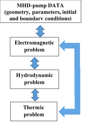
Figure 3. Coupling and resolution method
The boundary conditions can be specified as follows:
Inlet velocity for blood is considered 0.05m/s. No slip condition for all walls, $u(x, 0, z)=0, u(x, W, z)=0, u(x, y, 0)=0, u(x, y, H)=0$ Pressure in outlet was Outlet P= 0 Pa. walls: body force: FL (Lorentz force).
An initial temperature of 310 Kelvin is applied to the blood channel.
The Figure 3 represents the hydrodynamic-electromagnetic-thermal coupling method used in this study. The finite element method is applied to solve the magnetohydrodynamic and thermic problem to determine the velocity, the pressure and the temperature of the fluid in the channel. The weak coupling is used because it is easy for implementation and gives good results.
In the steady-state operation, the 3D MHD equations given here are conveniently solved using a finite element discretization approach. Due to the coupling between these sets of equations, an iterative solution approach is used. the electromagnetic components as given by the Gauss law and the magnetic induction are solved to determine the magnetic flux density (B). The electric potential (Φ), the electric field (E) and current densities (J) are then determined by solving the Poisson equation and Ohm's law. After that, the Lorentz force is calculated as a vector cross product of the current density and magnetic flux density vectors. Different results are represented in the next section.
Figure 4. Current density in the length of channel
The current density is presented in Figures 4 and 5. The Lorentz volumic force is presented in Figures 6-9. They present the Lorentz force in the MHD channel for different values of voltage and induction. The Figures 10 and 11 present the distribution of heat in the channel for different voltage values. The Figures 12-16 illustrate velocity of the liquid in the channel according the voltage, induction variations and electrodes dimensions.
Figure 5. Current density in the length of the channel
Figure 6. Distribution of Lorentz volumic force along the channel
Figure 7. Lorentz volumic force along the channel
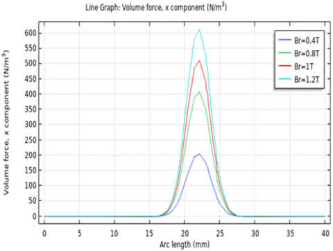
Figure 8. Volume force for different values of Br
Figure 9. Volume force for different values of Voltage
Figure 10. Distribution of temperature a long of the channel
Figure 11. Temperature for different values of electric voltage
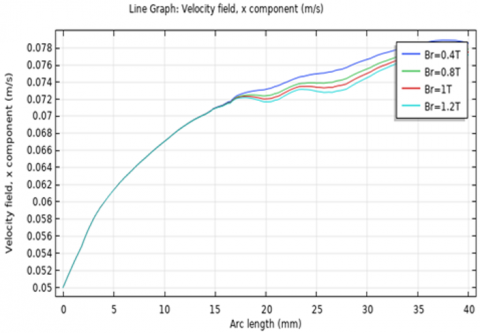
Figure 12. Blood velocity x component along the channel
Figure 13. Blood velocity field for different values of voltage
Figure 14. Blood velocity for different electrode length
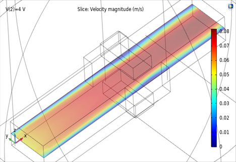
Figure 15. Distribution of blood velocity for Le=8mm and V=4V
Figure 16. Distribution of blood velocity for Le=8mm and V=10V
The Lorentz volumic force is presented in Figures 6 and 7. Where the force is created in the active length of the MHD micropump. The value of the force is high in the active part of the magnetic times Br=1.2T) in the middle of the channel, while the value of the magnetic flux near the electrodes is about 0.01T. The intensity of the magnetic field is stronger at the centre of the electromagnetic domain.
The volumic force is represented in Figures 8 and 9. The increasing of Br needed the increasing of Lorentz force; it attaints maximum value (200N/m3) for Br=0.4T and maximum value (600N/m3) for Br=1.2T.
Figures 8 and 9 illustrate Lorentz force contribution for different y positions for V=2V and Br=0.4T, the maximum value of the Lorentz force was located in the middle of the channel and 0N in the Iron for the applied volume. The volumic force is represented for different values of the electric voltage of 2V to 10V for a Br=0.8T. The maximum volumic force is 400N/m for V=2V and 2000N/m3 for 10V.
It considered that the electric current passing in any carrier solution is accompanied by a variation in temperature, figure 10 present the distribution of heat in the channel, we note that the temperature takes maximum values in the field near the electrodes.
Figure 11 illustrate the temperature profile along the channel for different values of tension, the increase in the value of electrical tension increases the blood temperature. In Figures 12-15 the effect of electromagnetic field on blood velocity for 0.8T and 2V, 4V and10V.
Figure 12 presents the effect of electromagnetic field on velocity profile in V=2 volt of electrical voltage and remanent magnetic density of 0.4 to 1.2 T is provided. we have a velocity profile while the maximum velocity of 0.078 m/ s in Y = 0 mm is reached. By variation of the magnetic flux density, there is a Small significant change of the velocity profile approximately 17mm from the channel inlet. We notice that the velocity is almost laminar and it was 0.05m/s in the inlet and maximal in the outlet of the channel, it attains value 0.08m/s.
We notice that for low voltages the speed of the blood varies almost linearly along the channel. But from some voltage values, we observe a drop in blood speed. This phenomenon is comparable to the armature magnetic reaction of the DC motor, Figure 12-14.
Also, we notice that the increase of the electrode length improves blood velocity profile, Figure 14.
In Figures 15 and 16 the velocity profile is represented, with an electrode length of 8mm under two voltage values V=4V and V=10V.
In Figure 15 we can see the presence of turbulence in the active part of the electrode.
This work presents a study of a DC-MHD pump which was realized in the laboratory. The goal of the study is to improve the efficiency of the pump by optimizing the electrical, magnetic and dimension parameters. The obtained results are matched expected based on theoretical considerations, as well as those reported by other authors.
The speed of blood flow presents a maximum at the middle of the MHD channel. However, the pressure of the fluid inside the pump corresponds to a notable increase in the exit of the channel. The effect of the electric field on the speed of the blood is noticeable and cannot be overlooked. It is observed that the increase in tension slows the movement of blood in the channel. This can be explained by the effects of the appearance of turbulence.
The speed and the temperature of the flow blood in MHD pump are strongly reliant on both the magnetic and electrical fields. The performance of the DC-MHD pump is optimal for 4V and 0.4T.
Another optimized prototype of DC-MHD pump will be designed according this study and included in the haemodialysis system.
[1] Else-Kröner-Str, Comprendre les Reins, Fresenius Medical care. Else-Kröner-Str. 161352 Bad Homburg, Allemangne. https://advancedrenaleducation.com/wparep/emea/imprint/.
[2] Louis, M. (2018). Le Traitement de l’insuffisance Renale Chronique par Dialyse: une Aventure Technologique et Humaine’. Ph.D. dissertation. Department of Electronic Engineering Lorraine University. https://hal.univ-lorraine.fr/hal-01733738.
[3] Mathew, A.T., Fishbane, S., Obi, Y., Kalantar-Zadeh, K. (2016). Preservation of residual kidney function in hemodialysis patients: Reviving an old concept. Kidney International, 90(2): 262-271. https://doi.org/10.1016/j.kint.2016.02.037
[4] Hueso, M., Navarro, E., Sandoval, D., Cruzado, J.M. (2019). Progress in the development and challenges for the use of artificial kidneys and wearable dialysis devices. Kidney Diseases, 5(1): 3-10. https://doi.org/10.1159/000492932
[5] Amrani, I. (2018). Conception d’un micro-actionneur à aimants permanents pour une application micro-pompe (Doctoral dissertation, Université Mohamed Khider–Biskra). http://thesis.univ-biskra.dz/id/eprint/3906.
[6] Bhatti, M.M., Zeeshan, A., Ellahi, R. (2016). Heat transfer analysis on peristaltically induced motion of particle-fluid suspension with variable viscosity: Clot blood model. Computer Methods and Programs in Biomedicine, 137: 115-124. https://doi.org/10.1016/j.cmpb.2016.09.010
[7] Homsy, A. (2006). Design, microfabrication, and characterization of MHD pumps and their applications in NMR environments (Doctoral dissertation, Université de Neuchâtel). file:///C:/Users/Meichuang/Downloads/these_HomsyA.pdf.
[8] Pasandi, A.M., Afrang, S., Dowlati, S., Sharafkhani, N., Rezazadeh, G. (2018). Study of volumetric flow rate of a micropump using a non-classical elasticity theory. International Journal of Engineering, 31(6): 986-996. https://dx.doi.org/10.5829/ije.2018.31.06c.17
[9] Khan, D., Hakim, M.A., Alam, M. (2015). Analysis of magneto-hydrodynamics jeffery-hamel flow with nanoparticles by hermite-padé approximation. International Journal of Engineering, 28(4): 599-607.
[10] Akinshilo, A.T., Sobamowo, G.M. (2017). Perturbation solutions for the study of MHD blood as a third grade nanofluid transporting gold nanoparticles through a porous channel. Journal of Applied and Computational Mechanics, 3(2): 103-113. https://dx.doi.org/10.22055/jacm.2017.12889
[11] Usman, M., Naheed, Z., Nazir, A., Mohyud-Din, S.T. (2014). On MHD flow of an incompressible viscous fluid. Journal of the Egyptian Mathematical Society, 22(2): 214-219. https://doi.org/10.1016/j.joems.2013.07.003
[12] Yu, H., Ye, W., Zhang, W., Zhao, Y., Liu, G. (2015). Design, fabrication and characterization of a travelling wave magnetic valveless micropump. Journal of Micromechanics and Microengineering, 25(6): 1-7. http://dx.chinadoi.cn/10.1088/0960-1317/25/6/065019
[13] Gregory, T.S., Cheng, R., Tang, G., Mao, L., Tse, Z.T.H. (2016). The magnetohydrodynamic effect and its associated material designs for biomedical applications: A state-of-the-art review. Advanced Functional Materials, 26(22): 3942-3952. https://doi.org/10.1002/adfm.201504198
[14] Ramesh, K., Tripathi, D., Bég, O.A., Kadir, A. (2019). Slip and hall current effects on Jeffrey fluid suspension flow in a peristaltic hydromagnetic blood micropump. Iranian Journal of Science and Technology, Transactions of Mechanical Engineering, 43(4): 675-692. https://doi.org/10.1007/s40997-018-0230-5
[15] Aoki, L.P., Schulz, H.E., Maunsell, M.G. (2013). An MHD study of the behavior of an electrolyte solution using 3D numerical simulation and experimental results. In COMSOL Conference Boston, Boston, MA, USA. http://dx.doi.org/10.13140/2.1.1398.6082
[16] Azimi-Boulali, J., Zakeri, M., Shoaran, M. (2019). A study on the 3D fluid flow of MHD micropump. Journal of the Brazilian Society of Mechanical Sciences and Engineering, 41(11): 478. https://doi.org/10.1007/s40430-019-1979-1
[17] Lim, S., Choi, B. (2009). A study on the MHD (magnetohydrodynamic) micropump with side-walled electrodes. Journal of Mechanical Science and Technology, 23(3): 739-749. https://doi.org/10.1007/s12206-008-1107-0
[18] Shahidian, A., Ghassemi, M., Mohammadi, R. (2012). Effect of nanofluid properties on magnetohydrodynamic pump (MHD). Advanced Materials Research, 403: 663-669. https://doi.org/10.4028/www.scientific.net/AMR.403-408.663
[19] Ghassemi, M., Barsi, Y.M. (2004). Effect of liquid film (indium) on thermal and electromagnetic distribution of an electromagnetic launcher with new armature. In 2004 12th Symposium on Electromagnetic Launch Technology, Snowbird, UT, USA, pp. 386-392. https://doi.org/10.1109/ELT.2004.1398111
[20] Ito, K., Takahashi, T., Fujino, T., Ishikawa, M. (2014). Influences of channel size and operating conditions on fluid behavior in a MHD micro pump for micro total analysis system. Journal of International Council on Electrical Engineering, 4(3): 220-226. https://doi.org/10.5370/JICEE.2014.4.3.220