Kouadria Mohamed Elbachir* | Azaiz Ahmed
© 2021 IIETA. This article is published by IIETA and is licensed under the CC BY 4.0 license (http://creativecommons.org/licenses/by/4.0/).
OPEN ACCESS
Nowadays the multi-inverter multi-machine conventional system takes a great interest of industrials like railway traction. The implementation of single inverter to dual motor makes all the system cheaper; soft operation, more robust and reliable; This paper is one of control methods proposed in the literature to improve performance of this system, a master slave and average control based in artificial neural networks direct torque control of bi asynchronous motors supplied by single three level inverter NPC is discussed. The result of theoretical analysis is tested with MATLAB SIMULINK environment. And through that, the possibility of DTC single inverter multi-motor system has been verified.
artificial neural networks, DTC, induction motor, master slave control, NPC single inverter
Induction machines have small size and high reliability economical, self-starting and more advantages make them the most widely used machines in residential, commercial, and industrial settings [1].
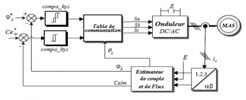
To control of IMs different methods was proposed in the literature for example in the middle of the 80s, Takahashi et al. [2, 3] and Depenbrock [4]. proposed a new strategy to control induction machine under the name of DTC (direct torque control of induction machine (Figure 1)). This new control is about to make the control of stator flux and torque uncoupled witch provide to AC drive control a robust and fast response with a simple control structure however it has his disadvantages [5, 6], variable switching frequency (causes noises), torque and flux waves around the hysteresis bands, at low speeds the control of flow is difficult; To improved it several works appeared we marked.
These techniques had considerable success in the fields of control and identification of non-linear systems; for DTC, these techniques allow the control of switching frequency and they have fast flow and torque responses with less noises.
In this paper we combined the tow last method to obtain a fast flow and torque responses with less noise
Figure 1. Block diagram of the classic 2-level DTC control
In classic DTC, one inverter generally drives one induction motor; are called single-machine single inverter systems; but this control cannot satisfy the needs of industrial applications such as electrical railway and high-power drive systems [5] and multi-machine multi-converter systems are expensive and can be just extensions of traditional drives. So, we need new system topology where one inverter supply more than one machines, this topology gives us more comfortable solution because its economical in cost, a smaller number of electronic components [12-15]. These systems are named Multi-Machine Single-Converter systems. There control is the topic of this study. A NPC level converter fed two inductions motors. This study proposes a new application of the average and master slave algorithms with implementation of artificial neural networks DTC.
The performance of the single-inverter multi-motor DTC system is verified with MATLAB Simulink.
2.1 DTC-neural switching table
Neural networks are a group of nonlinear functions, permitting work by learning a huge collection of models and nonlinear correction [16-20].
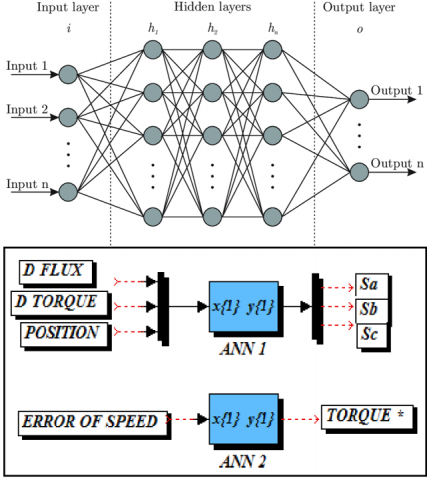
A neural network is a set of nonlinear operators interconnected between them, the signals came from the outside will be received by its inputs and then multiplied by constant weights, the sum of this weights multiplication maps to a nonlinear activation function; finally they will be transferred to the output of this neural network, which are actually the activities of certain neurons [16-20]. For applications considered in this paper is for the selection of inverter switching states, from the three inputs flux and torque provided from the output of hysteresis comparators and flux sector as its showing in Figure 2 and since the switching table does not depend on the parameters of the induction motor, neural network will be trained off-line.
Figure 2. Artificial neural networks switching table
3.1 Average algorithm
The concept of the control single-inverter dual motor system is based on the average algorithm where we vectored the operation states of multiple motors and averaging them to obtain an average motor. When there are differences in working conditions, the multiple motors can be driven according to this algorithm. In related theoretical derivation, the differences should be calculated by Eq. (1). [15, 16]:
$\left\{\begin{array}{l}
x y=z \\
\Delta x=\frac{x_{2}-x_{1}}{2}, \quad \bar{x}=\frac{x_{2}+x_{1}}{2} \\
\Delta y=\frac{y_{2}-y_{1}}{2}, \quad \bar{y}=\frac{y_{2}+y_{1}}{2} \\
\Delta x \bar{y}+\bar{x} \Delta y=\Delta z \\
\Delta x \Delta y+\overline{y x}=\bar{z}
\end{array}\right.$ (1)
where, x and y are variable grandeur.
3.2 Average direct torque control algorithm of single-inverter dual motor
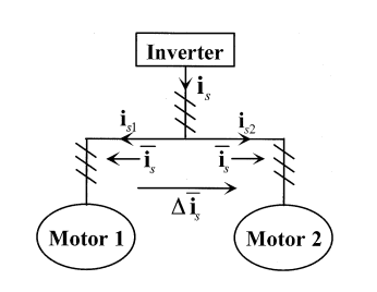
Multi-machine with single inverter system is always controlled as one machine but if the operating condition of the machines changes situation or lost; the current distribution of the two motors is unbalance. Vector control and direct torque control is proposed for two levels single-inverter fed dual machine [16-18]. In our study we discuss the implementation of the average algorithm to the direct torque control of NPC single inverter feeds two IM parallel-connected. In the practical applications, as electric traction generally uses only one inverter to fed two motors [18, 19]. When the number of motors is 2, it means the parameters of the two motors are same, the stator resistance, stator and rotor inductance and mutual inductance are all equal, then their variation is zero and to realize the DTC control we need the value of stator and rotor flux and torque. Figure 3 represent the flowing current provide by the inverter this current is equally divided to the dual induction motors connected in parallel. When the loads on motors are balanced, is1 is equal to is2. On other side when the tow motors had unbalanced loads is1 is different to is2 the average of is1 and is2 flowing in each stator coil winding and ∆is the current flowing directly from motor 1 into motor 2. Finally, to obtain the average model of the two motor we use Eq. (1) [16, 18].
Figure 3. Current flow for parallel connected IM
Then the average current in stator winding is:
$\left\{\begin{array}{l}
\overline{i_{s}}=\frac{1}{2}\left(i_{s 1}+i_{s 2}\right) \\
\Delta \overline{i_{s 12}}=\frac{1}{2}\left(i_{s 2}-i_{s 1}\right)
\end{array}\right.$ (2)
where, is1 represent the current of motor one and is2 for the second motor. After the alpha-beta (α β) transformation (Clarke transformation) we obtain new equation system.
$\left\{\begin{array}{l}
\overline{i_{s \alpha}}=\frac{1}{2}\left(i_{s \alpha 1}+i_{s \alpha 2}\right) \\
\overline{i_{s \beta}}=\frac{1}{2}\left(i_{s \beta 1}+i_{s \beta 2}\right) \\
\Delta \overline{i_{s \alpha}}=\frac{1}{2}\left(i_{s \alpha 2}-i_{s \alpha 1}\right) \\
\Delta \overline{i_{s \beta}}=\frac{1}{2}\left(i_{s \beta 2}-i_{s \beta 1}\right)
\end{array}\right.$ (3)
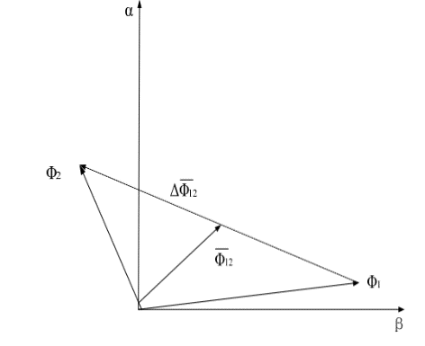
Similarly for magnetic induction flux, the average is presented in static α β coordinate Figure 4.
Figure 4. The average flux in dual-motor system
where, ϕs1 and ϕs2 is respectively the flux of the motor number one and motor tow. The stator flux of ϕs single motor:
$\phi_{s}=\int\left(V_{s}-R_{s} i_{s}\right)$ (4)
where, Vs is the stator voltage and is is the current of the phase and Rs is the resistance of stator. Then the stator flux of dual motors is:
$\left\{\begin{array}{l}
\frac{\mathrm{d} \overline{\phi_{s}}}{\mathrm{~d} t}=V_{s}-R_{s} \overline{i_{s}} \\
\overline{\phi_{s}}=\frac{1}{2}\left(\phi_{s 1}+\phi_{s 2}\right)
\end{array}\right.$ (5)
As shown in Figure 2, the average flux formula in the (α β) plane is:
$\left\{\begin{array}{l}
\overline{\phi_{s \alpha}}=\frac{1}{2}\left(\phi_{s \alpha 1}+\phi_{s \alpha 2}\right) \\
\overline{\phi_{s \beta}}=\frac{1}{2}\left(\phi_{s \beta 1}+\phi_{s \beta 2}\right) \\
\Delta \overline{\phi_{s \alpha}}=\frac{1}{2}\left(\phi_{s \alpha 2}-\phi_{s \alpha 1}\right) \\
{\Delta \overline{\phi_{s \beta}}}=\frac{1}{2}\left(\phi_{s \beta 2}-\phi_{s \beta 1}\right)
\end{array}\right.$ (6)
The rotor flux on single motor,
$\phi_{r}=\int\left(\frac{M}{\sigma L_{s}} \frac{1}{T_{r}}\left(\phi_{s}-\frac{L_{s}}{M} \phi_{r}\right)+j \omega_{r} \phi_{r}\right) \mathrm{d} t$ (7)
Finally, we applied the Eq. (1) the average torque of bi motors is:
$\left\{\begin{array}{l}
T_{e}=p\left(\overline{\varphi_{s} \times i_{s}}\right) \\
=p\left[\bar{\varphi}_{s} \times \bar{i}_{s}+\left(\Delta \varphi_{s} \times \Delta_{s}\right)\right] \\
=p\left(\overline{\varphi_{s \alpha} \times i_{s \beta}-\varphi_{s \beta} \times i_{s \alpha}}\right) \\
=p\left[{\overline{\varphi_{s \alpha}} \times\overline{{i}_{s \beta}}-\overline{{\varphi}_{s \beta}} \times \overline{{i}_{s \alpha}}}+\left(\Delta \varphi_{s \alpha} \times \Delta_{s \beta}\right)-\left(\Delta \varphi_{s \beta} \times \Delta_{s \alpha}\right)\right]
\end{array}\right.$ (8)
According to the theoretical analysis, the simulation model of the single inverter dual-motor DTC system has been built in MATLAB SIMULINK shown in Figure 5. The two dual induction motors used had the same parameters they listed in Table 1 one single Neutral Point Clamped inverter, tow hysteresis comparator four level four the torque and three level four the flux. the new in this DTC control is the average algorithm. The parameters of the two IMs will be received by the algorithm which will apply the Eqns. (2)-(8) to obtain mean motor with average parameters (current; voltage) and will be used in the DTC control.
Figure 5. Schematic of single inverter dual motor DTC system
Table 1. Parameter of induction motors
|
Parameter name |
Symbol |
Value |
Unit |
|
Stator Resistance |
Rs |
4.85 |
Ω |
|
Stator Inductance |
Ls |
0.274 |
A/m |
|
Rotor Resistance |
Rr |
3.81 |
Ω |
|
Rotor Inductance |
Lr |
0.274 |
A/m |
|
Mutual Inductance |
M |
0.258 |
A/m |
|
Number of Pole Pairs |
P |
2 |
|
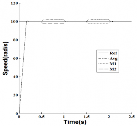
Figures 6-12 show the simulation results of the proposed method. These responses were for same load of the two motor (0.5 sec and 1 sec); the speed reference is a step-up function of value 100 rad/s. In the graphics, Motor 1, Motor 2 are indicated by ‘’M1, M2’’, respectively, Figures 13-20 displays the Unbalanced-Load simulation results.
Figure 6. Balanced-load for DTC – average speed response
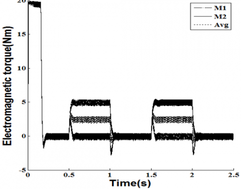
Figure 7. Balanced-load for DTC - torque response for dual motors
Figure 8. Balanced-load for DTC - stator flux of dual motors
Figure 9. Balanced-load for DTC - speed response of dual motors (M1, M2)
Figure 10. Balanced-load for DTC –load torque
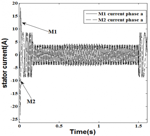
Figure 11. Balanced-load for DTC - stator current of dual
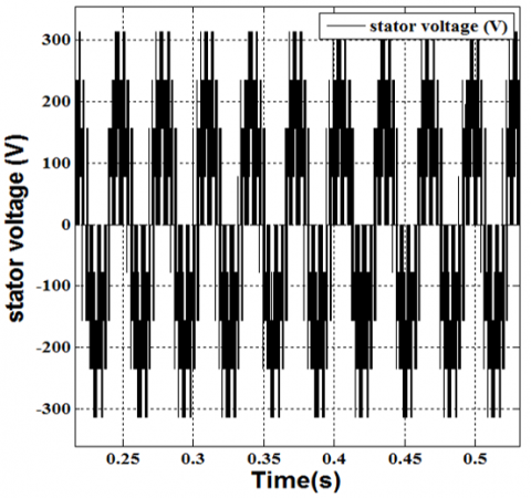
Figure 12. Balanced-load for DTC – 3 stator voltages out of the inverter
Figure 13. Unbalanced-load for DTC - speed response of dual motors
Figure 14. Unbalanced-Load for DTC zoomed viewed of speed response of dual motors
Figure 15. Unbalanced-load for DTC – load torque
Figure 16. Unbalanced-load for DTC – 3 stator voltages out of the inverter
Figure 17. Unbalanced-load for DTC - stator current of dual motor
Figure 18. Unbalanced-load for DTC - average stator flux
Figure 19. Unbalanced-load for DTC - stator flux of dual motors
Figure 20. Unbalanced-load for DTC - torque response for dual motors
In Unbalanced-Load (0.5s to 1s) there is a variation in the speed in the two motors the average of these two motors is equal to reference speed.
From the simulation result, we see that the performance of the average control of two motors connected in parallel in balanced-Load is very high. The two motors can follow the given speed quickly. So, the single-inverter dual-motor DTC system has favorable static and dynamic performance in this case. But because the inverter is common when both machines received different load, there is no control of individual machine. for that the average control allows us to drive the both motor by using a new motor had average parameters of the two-induction motor. And on the other hand, a three-level inverter provides a nearly sinusoidal current.
Figure 21 represents the principal of the new algorithm control, on the conventional DTC of induction motors to control the flux and electromagnetic torque the magnitude and position of the stator flux are adjusted respectively from that in this strategy some changes are made in order to make it applicable in a multi-machine system. There are two control loops for torque and one for the stator flux after the choice of the master machine because in this strategy, only the master machine is controlled without any consideration of the slave machine response or load changes. We clarified both control loop in the next section.
Figure 21. DTC of a two- induction machine master-slave control
5.1 Stator flux control loop
For this new algorithm, merely the master machine is controlled without any consideration of the slave machine response or load changes.
Choice of the master machine can be governed by certain factors such as the machine flux and torque. To prevent flux saturation at different situations, switch table algorithm is employed to choose the master motor which will be his stator flux controlled. this selection is based to an index. The product of stator resistance and electromagnetic torque Figure 21. The motor with the smallest product is chosen to be the master motor Figure 21 [15-26].
5.2 Electromagnetic torque control loops
Previously we have seen the direct torque control is choosing the appropriate voltage vector to fed the machine, this voltage allowed us to control on the same time stator flux and torque, this choice depends on the error of comparison between controlled and reference magnitude.
In two induction motor feds by one inverter, we have two torques for that we need to designing a new algorithm to find this error; first each motor had a classical control loop (5 level comparator) and then second control loop for the result of these two comparators the design of this control can be explained from Figure 22. Figure 21 represent the employment of this technique.
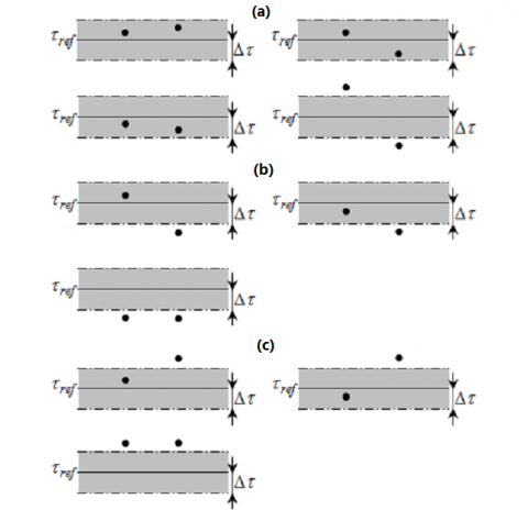
Figure 22. Possibilities of torque errors, (a) the torque should be kept constant, (b) the torque should be increased, (c) the torque should be reduced
In Figure 22, we see the possibilities of torque errors in torque control loop.
The black points characterize the electromagnetic torque typical situation for the both motors for the conditions depicted in Figure 22 (a), a voltage vector is applied to maintain the torque constant. and form the second conditions presented in Figure 22 (b), a voltage vector is applied to increase the torque finally, the last conditions showing in Figure 22 (c), a voltage vector is applied to reduction torque [15, 26]. We can resume the algorithm control in several pointe
From this point we obtain the next table.
Table 2. Proposed table in torque control loop
|
|
M1 |
|||||
|
M2 |
ST |
-2 |
-1 |
0 |
1 |
2 |
|
-2 |
-2 |
-1 |
-2 |
0 |
0 |
|
|
-1 |
-1 |
-1 |
-1 |
0 |
0 |
|
|
0 |
-2 |
-1 |
0 |
1 |
2 |
|
|
1 |
0 |
0 |
1 |
1 |
1 |
|
|
2 |
0 |
0 |
2 |
1 |
2 |
|
Finally, using the output of this table and the output of the stator flux control loop, the appropriate voltage vector is selected based on the conventional DTC switching look-up Table 2.
The proposed method is verified using MATLAB-SIMULINK a system with two induction motors with one inverter. The dual induction motors had the same parameters. Table 1 cover the parameters of the induction motors used.
The performance of this algorithm experienced by the balance test (same load torque) from 0s to 0.5s and unbalance test 0.5 s to 1 s (deferent load torque).
Both machines received different charge as shown on Figure 23, we can readily notice the system is always stable with quick response whatever the variation values of the torque loads are applied to the two machines.
When the load applied is same for the both the speeds of the motors follow up the reference speed imposed Figure 24, and from the unbalance test only the master motor (with smallest torque) has an excellent control for his speed Figure 24 and remarkable perfection in changing between the master and slave motors.
In Figure 25 the magnitude of the stator magnetic flux had a good stability for the both machines which ensures a good performance imposed by the DTC "master-slave" to the two motors in balance load. On the other side the stator flux when different are loaded torque between the two motors we see one of the two fluxes is chosen to be controlled.
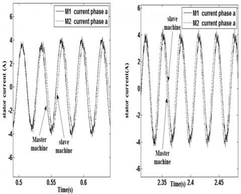
From Figure 26 the currents flow in the stator of the both motors are a good waveform and follow up the responses of the motors as far as the changes in loads are concerned.
Figure 23. Master-slave DTC torque response for dual motors
Figure 24. Master-slave DTC speed response of dual motors
Figure 25. Unbalanced-load for DTC stator flux of dual motors
Figure 26. Unbalanced-Load for DTC - stator current of dual motors
In this paper, the mathematical analysis of two new algorithm of direct torque control single-inverter dual-motor system has been discussed. Contrary to controls based on the orientation of the rotor flux the Direct Torque Control of an induction machine offers an acceptable solution to the trouble of robustness and dynamics, but using the hysteresis controllers produce torque oscillations for that to reduce it we choose to do the calculation with a high frequency processor, and also to minimize noise in the stator currents then make it as close to a sinusoidal wave we used three levels NPC inverter with neural control.
The average control present advantage in fast reaction to variation in loaded where the algorithm controls the average between two motors when the master slave control provides a satisfaction on redundancy control the simulation results verity that the proposed algorithms has better dynamic performance and had the ability to limit the flux below or equal to the rated in dual motor driving this allows us to apply it to railway traction system.
[1] Ciumbulea, G., Galan, N.E.C.U.L.A.I. (2008). Mathematical models and electrical equivalent schemes of the induction motor. Rev. Roum. Sci. Techn.–Électrotechn. et Énerg, 53(2): 151-162.
[2] Takahashi, I., Ohmori, Y. (1989). High-performance direct torque control of an induction motor. IEEE Transactions on Industry Applications, 25(2): 257-264. https://doi.org/10.1109/28.25540
[3] Takahashi, I., Noguchi, T. (1997). Take a look back upon the past decade of direct torque control [of induction motors]. In Proceedings of the IECON'97 23rd International Conference on Industrial Electronics, Control, and Instrumentation (Cat. No. 97CH36066), 2: 546-551. https://doi.org/10.1109/IECON.1997.671792
[4] Depenbrock, M. (1987). Direct self-control (DSC) of inverter fed induktion machine. In 1987 IEEE Power Electronics Specialists Conference, pp. 632-641. https://doi.org/10.1109/PESC.1987.7077236
[5] Gasbaoui, B., Chaker, A., Laoufi, A., Allaoua, B., Nasri, A. (2011). The efficiency of direct torque control for electric vehicle behavior improvement. Serbian Journal of Electrical Engineering, 8(2): 127-146. http://dx.doi.org/10.2298/SJEE1102127G
[6] Youb, L., Craciunescu, A. (2007). Etude comparative entre la commande vectorielle à flux orienté et la commande directe du couple de la machine asynchrone. PB Sci. Bull, Series C, 69(2): 113-128.
[7] Lascu, C., Boldea, I., Blaabjerg, F. (2000). A modified direct torque control for induction motor sensorless drive. IEEE Transactions on Industry Applications, 36(1): 122-130. https://doi.org/10.1109/28.821806
[8] Zhao, S., Peng, X. (2007). A modified direct torque control using space vector modulation (DTC-SVM) for surface permanent magnet synchronous machine (PMSM) with modified 4-order sliding mode observer. In 2007 International Conference on Mechatronics and Automation, pp. 1207-1212. https://doi.org/10.1109/ICMA.2007.4303720
[9] Flach, E., Hoffmann, R., Mutschler, P. (1997). Direct mean torque control of an induction motor. In European Conference on Power Electronics and Applications, 3: 3-672. https://doi.org/10.1109/ISIE.1997.651717
[10] Zhang, Y., Zhu, J., Guo, Y., Xu, W., Wang, Y., Zhao, Z. (2009). A sensorless DTC strategy of induction motor fed by three-level inverter based on discrete space vector modulation. In 2009 Australasian Universities Power Engineering Conference, pp. 1-6.
[11] Han, Y., Fan, X., Zhao, Z. (2011). A new flux observer based on voltage reconstruction for three-level DTC inverter. In 2011 IEEE Ninth International Conference on Power Electronics and Drive Systems, pp. 72-76. https://doi.org/10.1109/PEDS.2011.6147226
[12] Toufouti, R., Meziane, S., Benalla, H. (1997). Direct torque control for induction motor using fuzzy logic. Power Electron, 12(3). https://doi.org/10.1109/CCECE.1997.608355
[13] Gasbaoui, B., Chaker, A., Laoufi, A., Allaoua, B., Nasri, A. (2011). The efficiency of direct torque control for electric vehicle behavior improvement. Serbian Journal of Electrical Engineering, 8(2): 127-146. http://dx.doi.org/10.2298/SJEE1102127G
[14] Buja, G.S., Kazmierkowski, M.P. (2004). Direct torque control of PWM inverter-fed AC motors-a survey. IEEE Transactions on Industrial Electronics, 51(4): 744-757. https://doi.org/10.1109/TIE.2004.831717
[15] Joshi, B.M., Chandorkar, M.C. (2011). Effects of machine asymmetry on a two-machine direct torque controlled induction motor drive. In Proceedings of the 2011 14th European Conference on Power Electronics and Applications, pp. 1-10.
[16] Singh, B., Jain, P., Mittal, A.P., Gupta, J.R.P. (2006). Neural network based DTC IM drive for electric vehicle propulsion system. In 2006 IEEE Conference on Electric and Hybrid Vehicles, pp. 1-6. https://doi.org/10.1109/ICEHV.2006.352276
[17] Meziane, R.T.S., Benalla, H. (2007). Direct torque control for induction motor using intelligent techniques. Journal of Theoretical and Applied Information Technology, 3(3): 35-44. https://doi.org/10.1.1.152.8322
[18] Kumar, D., Thakur, I., Gupta, K. (2014). Direct torque control for induction motor using intelligent artificial neural network technique. International Journal of Emerging Trends & Technology in Computer Science (IJETTCS), 3(4): 44-50. https://doi.org/10.1.1.640.9083
[19] Ambarapu, S., Kumar, M.V. (2013). Neural network controllers in DTC of synchronous motor drives. International Journal of Power Electronics and Drive Systems, 3(3): 311. http://dx.doi.org/10.11591/ijpeds.v3i3.4023
[20] Menghal, P.M., Laxmi, A.J. (2013). Neural network based dynamic simulation of induction motor drive. In 2013 International Conference on Power, Energy and Control (ICPEC), pp. 566-571. https://doi.org/10.1109/ICPEC.2013.6527722
[21] Wan, H., Pan, Y. (2014). A single inverter multi-motor system based on direct torque control. UPD Sci. Bull. Series C, 76(2): 207-218.
[22] Wan, H., Pan, Y., Huang, J. (2012). Comparative study of VC and DTC for single-inverter dual-motor system. International Journal of Digital Content Technology and its Applications, 6(18): 587. http://dx.doi.org/10.4156/jdcta.vol6.issue18.70
[23] Matsuse, K., Kawai, H., Kouno, Y., Oikawa, J. (2004). Characteristics of speed sensorless vector controlled dual induction motor drive connected in parallel fed by a single inverter. IEEE Transactions on Industry Applications, 40(1): 153-161. https://doi.org/10.1109/TIA.2003.821805
[24] Gasbaoui, B., Nasri, A. (2012). A novel multi-drive electric vehicle system control based on multi-input multi-output PID controller. Serbian Journal of Electrical Engineering, 9(2): 279-291. https://doi.org/10.2298/SJEE1202279G
[25] Abdelfatah, N., Abdeldjebar, H., Bousserhane, I.K., Hadjeri, S., Sicard, P. (2008). Two wheel speed robust sliding mode control for electric vehicle drive. Serbian Journal of Electrical Engineering, 5(2): 199-216. https://doi.org/10.2298/SJEE0802199A
[26] Joshi, B.M., Chandorkar, M.C. (2014). Two-motor single-inverter field-oriented induction machine drive dynamic performance. Sadhana, 39(2): 391-407. https://doi.org/10.1007/s12046-014-0237-6