Mohd Ikhmil Fadzrizan Mohd Hanif | Mohd Ashraf Ahmad* | Julakha Jahan Jui
© 2021 IIETA. This article is published by IIETA and is licensed under the CC BY 4.0 license (http://creativecommons.org/licenses/by/4.0/).
OPEN ACCESS
This paper proposed the chaotic safe experimentation dynamics algorithm (CSEDA) to regulate angular tracking and vibration of the self-tuning PID controller for elastic joint manipulators. CSEDA was a modified version of the safe experimentation dynamics algorithm (SEDA) that used a chaos function in the updated equation. The chaos function increased the exploration capability, thus improving the convergence accuracy. In this study, two self-tuning PID controllers were used to regulate the rotating angle tracking and vibration for elastic joint manipulators in this control challenge. The suggested self-tuning PID controller's performance was evaluated in angular motion trajectory tracking, vibration suppression, and the pre-determined control fitness function. A self-tuned PID controller based on CSEDA could achieve superior control accuracy than a traditional SEDA and its variants.
vibration reduction, flexible mechanism, PID controller, self-tuned control, data-based method
Self-tuning control for elastic joint manipulators is a controller commonly used in control community. In general, self-tuning control for elastic joint manipulators is designed based on input and output data of the plant. It is now more prevalent than model-based control techniques [1, 2] due to the difficulty in establishing an accurate model for the complicated elastic joint manipulator [3]. In this respect, self-tuning control for flexible (elastic) joint manipulators is divisible into two types: feedforward and feedback controllers. Examples of feedforward controllers include command shaping and filtering techniques [4, 5]. After inputting some perturbations to the system, these forward controllers extract vibration frequencies information to synthesize the command shaper and filter.
Meanwhile, examples of feedback controllers encompass proportional-derivative and fuzzy-logic controllers. The majority of these flexible manipulators iteratively tune the feedback controller using input and output data information from the multi-agent-based optimisation methods [6, 7]. However, they require a large number of data sets to tune the feedback controller iteratively. In contrast, the feedforward controllers use single output data set only in constructing input shaping or filtering techniques. Nevertheless, the feedforward controller cannot deal with any disturbances, but the feedback controller system can do so due to its closed-loop nature. Hence, this paper focuses on the deliberation of the feedback controller.
There are various self-tuning tools for finding an optimal control parameter. For example, the spiral-dynamic algorithm (SDA) has been frequently used to find optimal control parameters of flexible/elastic manipulators. Some authors [8, 9] had combined SDA with the bacterial foraging algorithm (BFA) to generate the optimal proportional-derivative controller of the flexible manipulator system, and the hybrid of SDA-BFA produced better control and higher accuracy than the original SDA. A similar hybrid algorithm was used for tuning the fuzzy-logic-control parameters of the flexible manipulator system [10, 11]. These hybrid algorithms showed the best performance, achieving the highest accuracy while obtaining relatively faster convergence.
Meanwhile, the particle swarm optimiser (PSO) was used to determine the best parameter for the nonlinear and linear active rejection controllers [12]. Additionally, a genetic algorithm (GA) was used to estimate the best PID parameter with a command shaping technique for trajectory tracking and vibration suppression of a flexible manipulator [13]. Similarly, the flexible manipulator could also be regulated using a GA-tuned controller [14, 15]. Besides, the evolutionary computation (EC) method had also been used to regulate the tip position of a two-link flexible manipulator [16]. In contrast, the hierarchical PID controller [17] and the intelligent PID controller [18] of a one-link flexible manipulator were tuned using the bee algorithm and the artificial bee colony, respectively.
However, most of these algorithms require a substantial amount of computational time to secure the best controller parameter. It happens because the calculation time of iteration in the population-based self-tuning tools is proportional to the number of agents. Thus far, trajectory-based self-tuning methods that are commonly used to determine the optimal controllers include simulated annealing (SA) [19], random search [20], simultaneous perturbation stochastic approximation (SPSA) [21], and safe experimentation dynamics algorithm (SEDA) [22-24]. Among these trajectory-based self-tuning tools, SEDA is the most significant one due to its memory-based structure, simplicity, and fewer coefficient values [22-24], and it has often been used to tune the PID controller of an elastic joint manipulator [25, 26].
This paper proposed to use adaptive SEDA (ASEDA) [25] and levy-flight-based SEDA (LFSEDA) [26] for improving the convergence accuracy of the original SEDA. However, less exploration was produced in the initial searching stage because their updated equations still used the fixed value of step size gain or interval size. In resolving this issue, this paper adopted a chaotic function to replace the fixed interval size in the original updated equation of SEDA and named it as chaotic safe experimentation dynamics algorithm CSEDA). In this case, the interval size adopted a pre-defined chaotic map to produce various gains for the whole iteration. Since the use of chaotic map technique for assessing SEDA remains scarce, investigating the efficiency of the CSEDA for self-tuned control of elastic joint manipulators was justifiable.
Together, this study proposed a tuning technique based on the trajectory-based self-tuning tools that took less computation time. Specifically, this study investigated a self-tuning PID controller for an elastic joint manipulator using CSEDA with two PID controllers regulating angular tracking and vibration of the elastic joint manipulator. It aimed to create a self-tuned PID controller that allowed the rotary motion in tracking the desired trajectory with the least amount of vibration. The effectiveness of the recommended self-tuning PID controller was evaluated based on the trajectory of rotational angle motion, vibration reduction, and statistical analyses of the pre-determined control fitness function.
This section explains how to create a self-tuned PID controller for an elastic joint manipulator using CSEDA. First, the problem setup of the elastic joint manipulator's self-tuning PID controller is presented. The structure of a traditional PID controller and its parameters are discussed in detail. Second, the use of CSEDA to identify the best PID setting in minimising the control fitness function is deliberated.
2.1 Formulation of self-tuned PID controller problem
Figure 1 shows the PID control system block of the elastic joint manipulator; the notations H, $x_{R}(t)$, x(t), u(t), and α(t) denote the elastic joint manipulator plant, desired rotary angle reference, rotary angle output, the input of the system, and vibration angle, respectively. In this study, the mathematical model of H is taken from the study [27] and it is omitted in this paper due to limited space. Given that input was used only to control the motion of rotational and vibration angle simultaneously, the elastic joint manipulator was, thus, classified as an under-actuated plant.
Figure 1. The PID control system block for an elastic joint manipulator
Besides, the rotational and vibration angle were fed back to both PID controllers, denoted by the notations C1(s) and C2(s), respectively. Both PID controllers' expression is given by Eqns. (1) and (2).
$C_{1}(s)=p_{1}\left(1+\frac{1}{i_{1} s}+\frac{d_{1} s}{1+\left(d_{1} / n_{1}\right) s}\right)$ (1)
$C_{2}(s)=p_{2}\left(1+\frac{1}{i_{2} s}+\frac{d_{2} s}{1+\left(d_{2} / n_{2}\right) s}\right)$ (2)
where, p1, p2 $\in$ R, i1, i2 $\in$ R, d1, d2 $\in$ R and n1, n2 $\in$ R represent the proportional, integral, derivative, and filter gains, respectively. Eq. (3) below gives the fitness control function.
$F(\boldsymbol{p}, \boldsymbol{i}, \boldsymbol{d}, \boldsymbol{n})=\omega_{1} \hat{e}+\omega_{2} \hat{\alpha}+\omega_{3} \hat{u}$ (3)
where, for the time interval of [$t_{0}$, $t_{f}$].
$\hat{e}=\int_{t_{0}}^{t_{f}}\left|x_{R}(t)-x(t)\right|^{2} d t$ (4)
$\hat{\alpha}=\int_{t_{0}}^{t_{f}}|\alpha(t)|^{2} d t$ (5)
$\hat{u}=\int_{t_{0}}^{t_{f}}|u(t)|^{2} d t$ (6)
The notations p = [p1p2]T, i = [i1i2]T, d = [d1d2]T and n = [n1n2]T in Eq. (3) represent the eight tuning parameters in the PID controllers. Eq. (3) includes several weight coefficients to regulate this type of multi-objective function. These coefficients are denoted by ω1$\in$ R, ω2$\in$ R and ω3$\in$ R. Finally, the problem formulation of the self-tuned PID controller, Problem 1, is given below:
Problem 1: Find the PID controllers C1(s) and C2(s) that reduce the fitness function in Eq. (3) using the specified plant H and both PID controllers with the given executed u(t) and x(t) data in Figure 1.
Remark 1: In this study, it is assumed that the structure of the PID controllers C1(s) and C2(s) are given in advanced. Note that the researcher can use different PID formula or PID structure to obtain better results. However, it is not the main concern here, since this paper is more focus on the development of the effective tools (i.e., CSEDA) for self-tuning PID.
2.2 Self-tuned PID using CSEDA
The proposed CSEDA algorithm was employed in this section to estimate the best PID controller for the elastic joint control problem. This subsection briefly explains the original SEDA [22]. The upgraded version of SEDA, known as CSEDA, is then discussed. Finally, the procedure for using the CSEDA algorithm to identify the best PID controller for an elastic joint manipulator is presented.
Consider the following minimisation problem to define the concept of a self-tuning tool:
$\min _{v \in \mathbf{R}^{n}} O(\boldsymbol{v})$ (7)
where, O: Rn ® R is a fitness function with the tuning-parameter vector $v \in \mathbf{R}^{n}$. The SEDA [22] updates $\boldsymbol{v} \in \mathbf{R}^{n}$ to find an optimal solution $\boldsymbol{v}^{*} \in \mathbf{R}^{n}$ of Eq. (7). The updated equation of SEDA is given by Eq. (8) below.
$v_{i}(k+1)=\left\{\begin{array}{c}m\left(\bar{v}_{i}-g r_{2}\right) \text { if } r_{1} \leq P, \\ \bar{v}_{i} \quad \text { if } r_{1}>P,\end{array}\right.$ (8)
where, k is the number of iterations, $v_{i} \in \mathbf{R}$ represents ith component of $\boldsymbol{v} \in \mathbf{R}^{n}$, and $\bar{v}_{i} \in \mathbf{R}$ represents ith component of $\overline{\boldsymbol{v}} \in \mathbf{R}^{n}$. The notation $\bar{v}$ is the tuning parameter’s current best value. The notation $r_{1} \in \mathbf{R}$ represents the random value created uniformly between 0 and 1, P represents the probability of changing a component of the tuning parameter and g represents the size of the interval used to determine the random steps of $v_{i} \in \mathbf{R}$. In Eq. (8), the function m is given by Eq. (9) below.
$m(.)=\left\{\begin{array}{c}v_{\max }, \bar{v}_{i}-g r_{2}>v_{\max } ,\\ \bar{v}_{i}-g r_{2}, v_{\min } \leq \bar{v}_{i}-g r_{2} \leq v_{\max }, \\ v_{\min }, \bar{v}_{i}-g r_{2}<v_{\min },\end{array}\right.$ (9)
where, $r_{2}$ is another random value produced separately from $r_{1}$, while the pre-specified lower and upper bounds of tuning parameters are defined by $v_{\min }$ and $v_{\max }$, respectively. The complete steps of SEDA (S1 – S5) are given below.
S1: Set the values of $v_{\min }, v_{\max }$, g, and P; determine the initial values of the tuning parameter v(0); execute the fitness function O(v(0)) and let $\overline{\boldsymbol{v}}=\boldsymbol{v}(0)$ and $\bar{O}=O(v(0))$.
S2: If the value $O(\boldsymbol{v}(k))<\bar{O}$, perform $\bar{v}=v(k)$ and $\bar{O}=O(v(k))$. Otherwise, proceed to S3.
S3: Produce random values $r_{1}$ and $r_{2}$ separately and calculate the updated equation in Eq. (8).
S4: Execute the updated fitness function $O\left(v_{i}(k+1)\right)$.
S5: Repeat S2 when the pre-defined termination criterion (i.e., the maximum number of iterations $k_{\max }$) is not satisfied. If the algorithm stops, record the optimum tuning parameter $\boldsymbol{v}^{*}:=\arg \min _{\boldsymbol{v} \in\{v(0), v(1), \ldots, v(k+1)\}} O(\boldsymbol{v})$.
Based on our initial study of the SEDA performance in the self-tuning process [22], the updated Eq. (8) used a fixed interval g for the whole iteration. Thus, CSEDA was proposed as the self-tuning tool to yield the optimum PID controller for an elastic joint manipulator, and it modified the updated Eq. (8) as Eq. (10) below.
$v_{i}(k+1)=\left\{\begin{array}{c}m\left(\bar{v}_{i}-\tilde{g}(k+1) r_{2}\right) \text { if } r_{1} \leq P, \\ \bar{v}_{i} \quad \text { if } r_{1}>P,\end{array}\right.$ (10)
where, m is the same function of Eq. (9) that limits the value of $\bar{v}_{i}-\tilde{g}(k+1) r_{2}$ according to $v_{\min }$ and $v_{\max }$, while $\tilde{g}(k+1)$ is a generated chaotic expression, as shown in Eq. (11) below.
$\tilde{g}(k+1)=\sin (\pi \tilde{g}(k))$. (11)
Eq. (11) was inspired from the sinusoidal chaotic equation [28]. The use of the enhanced updated Eq. (10) allowed the interval size to vary in iteration according to the sinusoidal map in Eq. (11), thus executing more exploration of the tuning parameter. Thence, higher fitness function accuracy could be expected using this new version of updated Eq. (10).
Besides, based on the enhanced updated Eq. (10), complete steps to apply CSEDA as the self-tuning tools in obtaining the optimal PID controllers for an elastic joint manipulator are given below:
P1: Set the maximum iteration $k_{\max }$; let $O(\boldsymbol{v})=F(\boldsymbol{p}, \boldsymbol{i}, \boldsymbol{d}, \boldsymbol{n})$ and $v_{i}=\log \psi_{i}$. The tuning parameter vector is given as $\psi=\left[p_{1} i_{1} d_{1} n_{1} p_{2} i_{2} d_{2} n_{2}\right]^{\mathrm{T}}$ and $\psi_{i}=10^{v_{i}}(i=1,2, \ldots, 8)$.
P2: Compute the updated Eq. (10) of CSEDA.
P3: Once $k_{\max }$ is reached, record the optimal tuning parameter $\boldsymbol{v}^{*}=\bar{v}$. Then, apply the value to PID controllers $\psi^{*}=\left[\begin{array}{llll}10^{\bar{v}_{1}} & 10^{\bar{v}_{2}} & \cdots & 10^{\bar{v}_{8}}\end{array}\right]^{\mathrm{T}}$ in Figure 1.
This section demonstrates the effectiveness of the CSEDA in estimating the optimal PID controller for an elastic joint manipulator. The fitness function's convergence curve response in Eq. (3), rotary motion, vibration angle, input responses, statistical evaluations of the fitness function, integral quadratic error, and integral quadratic input are presented and analysed. The statistical performance of CSEDA was evaluated in this study using 25 independent trials. Besides, the performance was compared among the proposed CSEDA and the original SEDA, ASEDA [25], and LFSEDA [26].
The execution of the PID control strategy for elastic joint manipulator was based on the model H of [27]. The reference trajectory of rotation angle is given in Eq. (12) below.
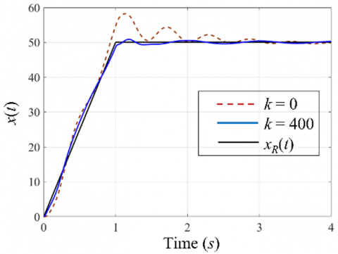
$x_{R}(t)=\left\{\begin{array}{cc}50 t, & 0 \leq t \leq 1, \\ 50, & 1<t \leq 4.\end{array}\right.$ (12)
In Eq. (12), the elastic joint manipulator was required to track the ramp trajectory motion in the first second before settling down at 50º until the fourth second. The main goal was to yield the best PID controller for the rotational angle motion to trace the pre-determined target trajectory in Eq. (12) with the lowest vibration angle. Table 1 shows the coefficients of SEDA, ASEDA [25], LFSEDA [26], and CSEDA. The values of weighting coefficients were set as ω1= 400, ω2 = 400 and ω3 = 1. The initial value of the tuning parameter for all the algorithms was set to be the same, and it was given by $\boldsymbol{v}$ (0) = [0.5 1.0 0.0 1.0 0.0 1.0 0.0 2.0]T. These initial values were chosen after a series of preliminary tests to ensure a stable closed-loop response.
Table 1. The coefficients of SEDA, ASEDA [25], LFSEDA [26] and CSEDA
|
SEDA |
ASEDA [25] |
LFSEDA [26] |
CSEDA |
|
$g=0.02$ $P=0.66$ $v_{\min }=-3$ $v_{\max }=3$ |
$g=0.02$ $P=0.66$ $v_{\min }=-3$ $v_{\max }=3$ $K_{a}=0.03$ |
$g=0.02$ $P=0.66$ $v_{\min }=-3$ $v_{\max }=3$ $\beta=1$ |
$\tilde{g}(0)=0.7$ $P=0.66$ $v_{\min }=-3$ $v_{\max }=3$ |
Figure 2 shows the fitness function convergence response after 400 iterations for generating the fitness function of 3.8130×10³. This value was contributed by the best tuning parameter values $\boldsymbol{v}$* = [1.0293 -1.1653 -0.3991 2.6729 -0.9806 -3.0000 -1.1804 -0.2848]T that corresponded to $\psi^{*}$= [10.6985 0.0683 0.3989 470.8511 0.1046 0.0010 0.0660 0.5190]T. The convergence curve of the fitness function was chosen as the best convergence curve from 25 independent trials. Figures 3, 4, and 5 show that CSEDA had reduced the fitness function of Eq. (3) and created better angular motion, vibration angle, and input responses. The brown-dashed line represented the response of the initial PID controller parameters at iteration k = 0, whereas the thick blue line denoted the optimum PID controller values at iteration k = 400. The self-tuning PID via CSEDA improved the rotational motion tracking with very little overshoot and nearly no steady-state error (Figure 3). For the vibration angle (Figure 4), the optimal PID controllers reduced the oscillation within two seconds, i.e., faster than the initial PID controllers. However, when compared to the initial PID controllers, the initial PID controllers created a somewhat higher magnitude of vibration angle, ranging from -1.87 to 2.15 degrees. Similarly, the output from the optimum PID controllers generated a lower settling time, but a higher magnitude of the input.
Figure 2. Convergence curve response
Table 2 compares the performance of all self-tuning methods after 25 independent trials with the best results shown in bold numerical values. LFSEDA [26] produced the lowest mean and worst values of fitness function while CSEDA and ASEDA [25] yielded the lowest (best) and standard deviation values, respectively. It shows that most of the SEDA variants have improved the fitness function’s accuracy, particularly in terms of tracking error and control input energy.
Table 2. Statistical performances between SEDA, ASEDA [25], LFSEDA [26] and CSEDA
|
Algorithm |
SEDA |
ASEDA [25] |
LFSEDA [26] |
CSEDA |
|
|
$F(\boldsymbol{p}, \boldsymbol{i}, \boldsymbol{d}, \boldsymbol{n})$ $\left(\times 10^{3}\right)$ |
Mean |
4.1007 |
4.1006 |
4.0761 |
4.0858 |
|
Best |
4.0790 |
4.0767 |
3.9304 |
3.7415 |
|
|
Worst |
4.1499 |
4.1515 |
4.1057 |
4.1527 |
|
|
Std. |
0.0138 |
0.0135 |
0.0281 |
0.0684 |
|
|
$\hat{e}+\hat{\alpha}$ |
Mean |
3.4709 |
3.4692 |
3.4372 |
3.4910 |
|
Best |
3.3601 |
3.3422 |
3.2960 |
3.2496 |
|
|
Worst |
3.6193 |
3.5566 |
3.5416 |
4.001 |
|
|
Std. |
0.0590 |
0.0545 |
0.0522 |
0.1403 |
|
|
$\hat{u}\left(\times 10^{3}\right)$ |
Mean |
2.7123 |
2.7129 |
2.7012 |
2.6894 |
|
Best |
2.6782 |
2.6807 |
2.5137 |
2.3393 |
|
|
Worst |
2.7578 |
2.7765 |
2.7743 |
2.8024 |
|
|
Std. |
0.0215 |
0.0226 |
0.0405 |
0.0894 |
|
Compared to the original SEDA, ASEDA [25], and LFSEDA [26], CSEDA produced substantially lower values in the best fitness function, tracking error, and the controller’s output. In terms of average values, CSEDA produced the lowest values in the controller’s outputs and slightly competitive values with LFSEDA [26] in the fitness function. However, other SEDA variations yielded slightly superior outcomes based on a fitness function, tracking error, and consistency of the controller’s output, as measured by the worst value and standard deviation. Overall, the suggested CSEDA increased the PID control accuracy, especially on the mean and the best value of fitness function and the controller’s outputs when compared to the original SEDA and other SEDA variants.
Figure 3. Rotary motion responses
Figure 4. Vibration angle responses
Figure 5. Controller output responses
This paper presented a self-tuning PID for an elastic joint manipulator using CSEDA. The proposed CSEDA-based technique could improve the PID control accuracy while generating lower best fitness function values, integral quadratic error, and integral quadratic input than the original SEDA, ASEDA, and LFSEDA self-tuning methods. In particular, the CSEDA-based technique produces 8.3%, 3.3%, 12.7% improvements in the best fitness function, integral quadratic error, and integral quadratic input values than the original SEDA. The rotary motion tracking, vibration angle, and controller output responses confirmed these findings. The CSEDA method could tune a variety of controllers, including fuzzy logic and neural network controllers.
The authors would like to thank the Ministry of Higher Education for providing financial support under Fundamental Research Grant Scheme (FRGS) No. FRGS/1/2021/TK0/UMP/02/5 and Universiti Malaysia Pahang for laboratory facilities as well as additional financial support under Internal Research grant PGRS1903141.
[1] Andrade, J.M., Christopher, E. (2020). LMI-Based sliding mode controller design for an uncertain single-link flexible robot manipulator. In Portuguese Conference on Automatic Control, Springer, Cham, pp. 696-706. https://doi.org/10.1007/978-3-030-58653-9_67
[2] Khairudin, M. (2021). Vibration control using pole placement with proportional gain of a flexible manipulator incorporating payload. Journal of Control, Automation and Electrical Systems, 32: 1164-1176. https://doi.org/10.1007/s40313-021-00752-7
[3] Khairudin, M., Mohamed, Z., Husain, A.R., Ahmad, M.A. (2010). Dynamic modelling and characterisation of a two-link flexible robot manipulator. Journal of Low Frequency Noise, Vibration and Active Control, 29(3): 207-219. https://doi.org/10.1260%2F0263-0923.29.3.207
[4] Ahmad, M.A., Raja Ismail, R.M.T., Ramli, M.S., Nasir, A.N.K., Hambali, N. (2009). Feed-forward techniques for sway suppression in a double-pendulum-type overhead crane. Proceedings of International Conference on Computer Technology and Development, pp. 173-178. https://doi.org/10.1109/ICCTD.2009.8
[5] Liu, C., Youdong, C. (2018). Combined S-curve feedrate profiling and input shaping for glass substrate transfer robot vibration suppression. Industrial Robot: An International Journal, 45(4): 549-560. https://doi.org/10.1108/IR-11-2017-0201
[6] Cui, L., Wang, H., Chen, W. (2020). Trajectory planning of a spatial flexible manipulator for vibration suppression. Robotics and Autonomous Systems, 123: 103316. https://doi.org/10.1016/j.robot.2019.103316
[7] Li, Y., Ge, S.S., Wei, Q., Gan, T., Tao, X. (2020). An online trajectory planning method of a flexible-link manipulator aiming at vibration suppression. IEEE Access, 8: 130616-130632. https://doi.org/10.1109/ACCESS.2020.3009526
[8] Nasir, A.N.K., Tokhi, M.O., Abdul Ghani, N.M., Ahmad, M.A. (2012). A novel hybrid spiral-dynamics bacterial-foraging algorithm for global optimization with application to control design. Proceedings of 12th UK Workshop on Computational Intelligence (UKCI), pp. 1-7. https://doi.org/10.1109/UKCI.2012.6335764
[9] Nasir, A.N.K., Tokhi, M.O., Abdul Ghani, N.M., Ahmad, M.A. (2012). A novel hybrid spiral dynamics bacterial chemotaxis algorithm for global optimization with application to controller design. Proceedings of UKACC International Conference on Control, pp. 753-758. https://doi.org/10.1109/CONTROL.2012.6334724
[10] Nasir, A.N.K., Tokhi, M.O. (2015). Novel metaheuristic hybrid spiral-dynamic bacteria-chemotaxis algorithms for global optimisation. Applied Soft Computing, 27: 357-375. https://doi.org/10.1016/j.asoc.2014.11.030
[11] Nasir, A.N.K., Ahmad, M.A., Tokhi, M.O. (2021). Hybrid spiral-bacterial foraging algorithm for a fuzzy control design of a flexible manipulator. Journal of Low Frequency Noise, Vibration and Active Control, In press. https://doi.org/10.1177%2F14613484211035646
[12] Humaidi, A.J., Badir, H.M. (2018). Linear and nonlinear active rejection controllers for single-link flexible joint robot manipulator based on PSO tuner. J. Eng. Sci. Technol. Rev., 13(6): 2272-2278.
[13] Aldbrez, F.M., Alam, M.S., Tokhi, M.O. (2005). Input-shaping with GA-tuned PID for target tracking and vibration reduction. Proceedings of the 2005 IEEE International Symposium on, Mediterrean Conference on Control and Automation Intelligent Control, pp. 485-490. https://doi.org/10.1109/.2005.1467063
[14] Meng, Q., Lai, X., Yan, Z. (2018). A control strategy with zero residual vibration for a planar single-link flexible manipulator. In 2018 37th Chinese Control Conference (CCC), pp. 344-347. https://doi.org/10.23919/ChiCC.2018.8483640
[15] Meng, Q.X., Lai, X.Z., Wang, Y.W., Wu, M. (2018). A fast stable control strategy based on system energy for a planar single-link flexible manipulator. Nonlinear Dynamics, 94(1): 615-626. https://doi.org/10.1007/s11071-018-4380-1
[16] Subudhi, B., Ranasingh, S., Swain, A. (2011). Evolutionary computation approaches to tip position controller design for a two-link flexible manipulator. Archives of Control Sciences, 21(3): 269-285. https://doi.org/10.2478/v10170-010-0043-2
[17] Pham, D.T., Koç, E., Kalyoncu, M., Tınkır, M. (2008). Hierarchical PID controller design for a flexible link robot manipulator using the bees algorithm. Proceedings of 6th International Symposium on Intelligent Manufacturing Systems, pp. 1-6.
[18] Hadi, M.S., Darus, I.Z.M., Tokhi, M.O., Jamid, M.F. (2019). Active vibration control of a horizontal flexible plate structure using intelligent proportional–integral–derivative controller tuned by fuzzy logic and artificial bee colony algorithm. Journal of Low Frequency Noise, Vibration and Active Control, 39(4): 1159-1171. https://doi.org/10.1177%2F1461348419852454
[19] Ramli, A.S., Rashid, M.I.M., Ahmad, M.A. (2020). Energy management strategy of hev based on simulated annealing. International Journal of Integrated Engineering, 12(2): 30-37. Retrieved from https://publisher.uthm.edu.my/ojs/index.php/ijie/article/view/5297.
[20] Ahmad, M.A., Hao, M.R., Ismail, R.M.T.R., Nasir, A.N.K. (2016). Model-free wind farm control based on random search. In 2016 IEEE International Conference on Automatic Control and Intelligent Systems (I2CACIS), pp. 131-134. https://doi.org/10.1109/I2CACIS.2016.7885302
[21] Ahmad, M.A., Azuma, S.I., Sugie, T. (2014). Performance analysis of model-free PID tuning of MIMO systems based on simultaneous perturbation stochastic approximation. Expert Systems with Applications, 41(14): 6361-6370. https://doi.org/10.1016/j.eswa.2014.03.055
[22] Marden, J.R., Ruben, S.D., Pao, L.Y. (2013). A model-free approach to wind farm control using game theoretic methods. IEEE Transactions on Control Systems Technology, 21(4): 1207-1214. https://doi.org/10.1109/TCST.2013.2257780
[23] Mohd Hanif, M.I.F., Suid, M.H., Ahmad, M.A. (2019). A piecewise affine PI controller for buck converter generated DC motor. International Journal of Power Electronics and Drive Systems, 10(3): 1419-1426. http://doi.org/10.11591/ijpeds.v10.i3.pp1419-1426
[24] Abdul Syukor, N.S., Ahmad, M.A., Mohd Tumari, M.Z. (2017). Data-driven PID tuning based on safe experimentation dynamics for control of liquid slosh. Proceedings of 8th IEEE Control and System Graduate Research Colloquium, pp. 62-66. https://doi.org/10.1109/ICSGRC.2017.8070569
[25] Ahmad, M.A., Ishak, H., Nasir, A.N.K., Abd Ghani, N.M. (2021). Data-based PID control of flexible joint robot using adaptive safe experimentation dynamics algorithm. Bulletin of Electrical Engineering and Informatics, 10(1): 79-85. https://doi.org/10.11591/eei.v10i1.2472
[26] Ahmad, M.A., Mohd Rashid, M.I., Sulaiman, M.H., Suid, M.H., Mohd Tumari, M.Z. (2020). Levy flight safe experimentation dynamics algorithm for data-based PID tuning of flexible joint robot. Proceedings of IEEE Symposium on Computer Applications and Industrial Electronics, pp. 108-112. https://doi.org/10.1109/ISCAIE47305.2020.9108840
[27] Rotary Flexible Joint User Manual. (2008). Quanser Inc., Markham, ON, Canada.
[28] Wang, G.G., Guo, L., Gandomi, A.H., Hao, G.S., Wang, H. (2014). Chaotic krill herd algorithm. Information Sciences, 274: 17-34. https://doi.org/10.1016/j.ins.2014.02.123