Akhilesh Kumar* | Pradip K. Sadhu | Jay Singh
© 2021 IIETA. This article is published by IIETA and is licensed under the CC BY 4.0 license (http://creativecommons.org/licenses/by/4.0/).
OPEN ACCESS
Nowadays, the matrix converter (MC) has become the prominent power converter. Its unique qualities like single-stage ac to ac conversion, bidirectional power flow, sinusoidal response, unity power factor, and no need for dc-link makes it superior among all power converters. This archival literature investigates the various pulse width modulation (PWM) methods and proposed a novel pulse width modulation (PWM) method named Time Equivalent space vector pulse width modulation. In this article this novel modulation method is compared with exiting carrier-based pulse width control and space vector control methods for a 3 phase to 3 phase matrix converters. Simulation model is built in Matlab and comparative analysis based on total harmonic distortion (THD) will be given for different methods. Simulation results revealed that total harmonic distortion (THD) of Time Equivalent space vector PWM is least so this novel method is best and more efficient in comparison to others.
matrix converter, carrier-based PWM, space vector PWM, time equivalent space vector PWM
In recent times the power conversion from AC to AC is done by traditionally back-to-back converters in which there are two conversion stages. Firstly, AC is converted into DC by rectifier circuit and then DC is again converted into AC by inverter circuit. The rectifier circuit and inverter circuit are linked by a bulky capacitor called a DC link. This dc link is used for energy storage.
A drawback of this AC to AC converter is that there are two stages of power conversion due to which losses are high and the presence of dc-link makes its structure very bulky and complicated. Due to the presence of dc-link life of converter becomes less, converter design also becomes so much complex and overall, the efficiency of the converter decreases.
To overcome the drawbacks of traditional back-to-back converters the researchers are working on a new converter topology called matrix converter (MC). The most attractive features of matrix converter which overcome the drawbacks of the traditional back-to-back converters are given as following: No need for an energy storage element, the waveform of input and output is pure sinusoidal, unity input power factor, harmonics content is very low, and single-stage energy conversion. These all features of matrix converter forced the researchers to work on it so that efficiency of the power converter can be maximized.
The first time this AC to AC converter called matrix converter was introduced by Gyugi and Pelly in 1976 [1]. Then matrix converter came with a power transistor in 1978 [2]. In the era of (the 1980s), there was a huge work done in the field of matrix converter by Venturini and Alesina [3, 4]. A matrix converter is made of a different combination of bidirectional switches, with the help of these switches power conversion takes place in a single-stage without any energy storage element.
By using a different combination of bidirectional switches and different switching methods the matrix converter can also work as an AC to DC converter and DC to AC converter. Since with the help of a matrix converter multiple power conversion can take place hence it can be called a universal power converter [5].
The merits of matrix converters that make them superior over two stages converters are the absence of energy storage elements, simple fabrication, single-stage power conversion, bidirectional power flow, low harmonics, and more efficiency [6].
Figure 1. Three-phase to three-phase matrix converter
Configuration of an AC to AC power converter which converts three-phase power to three-phase power is shown in Figure 1. Since there is no need for energy storage elements in matrix converter hence life span and efficiency of matrix converter increases and complication of switching schemes decreases in comparison to traditional back-to-back converters. The matrix converter has a requirement of filters to remove the ripples produced in switching [7].
In this article, the author discusses about different PWM schemes of power conversion. After that, authors’ presented a novel PWM scheme named Time Equivalent space vector PWM method for three phase to three phase matrix converter. A simulation model is built in MatLab for novel Time Equivalent space vector PWM. Its simulation results are compared with others PWM schemes which shows that this novel method gives least THD. Thus, it is best and more efficient. There is a wide future scope of this novel method in wind power plants. This method with matrix converter can be used in wind power plants where output AC power from wind plants can be given to the AC grid in single stage more effectively [8, 9].
Among all switching techniques, the pulse width modulation is the most basic control technique used for power conversion in various power converters. The main object of any switching scheme is to generate variable frequency, voltage, and current at the output. In this section, different PWM techniques will be explained for a 3-phase matrix converter. Among which carrier-based PWM and space vector PWM is already existing and time equivalent space vector PWM is proposed in this paper. The schemes covered in this are (1) Carrier-based sinusoidal PWM scheme, (2) Space vector PWM scheme, and (3) Proposed Time equivalent space vector pulse width modulation scheme.
2.1 Carrier-based pulse width modulation
The relationship of input-output voltage and current for a three-phase to three-phase matrix converter can be written as given in the following equations where VA, VB, and VC denotes output voltages and Va, Vb and Vc denotes the input voltages. Duty ratios are represented by day .... etc.
$\left[\begin{array}{l}
V_{A} \\
V_{B} \\
V_{C}
\end{array}\right]=\left[\begin{array}{lll}
d_{a A} & d_{b A} & d_{c A} \\
d_{a B} & d_{b B} & d_{c B} \\
d_{a C} & d_{b C} & d_{c C}
\end{array}\right]\left[\begin{array}{c}
V_{a} \\
V_{b} \\
V_{c}
\end{array}\right]$ (1)
$\left[\begin{array}{l}
i_{a} \\
i_{b} \\
i_{c}
\end{array}\right]=\left[\begin{array}{lll}
d_{a A} & d_{b A} & d_{c A} \\
d_{a B} & d_{b B} & d_{c B} \\
d_{a c} & d_{b c} & d_{c C}
\end{array}\right]\left[\begin{array}{l}
i_{A} \\
i_{B} \\
i_{C}
\end{array}\right]$ (2)
2.1.1 Generation of switching signals
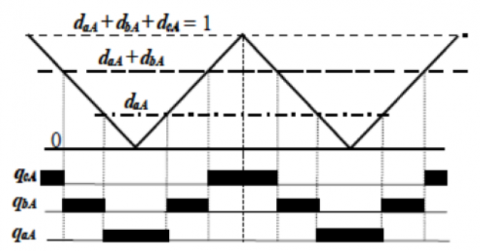
To generate the switching signal for each switch the duty ratios are compared by the triangular carrier wave. In Figure 2 it is shown that how the switching signals connect the input side three-phase to output side three-phase by comparing the carrier signal.
By using the same process signals for the switches in the other two legs can be produced. To produce the PWM signal d aA and d aA+d bA are compared by the carrier signal similarly the switching signal for the third switch are obtained by applying the same logic. The switching sequence, which is the order in which the three input phase voltages are connected to the output load, is a-b-c-b-a [10].
Figure 2. Generation of switching signals using carrier comparison with a triangular waveform
2.1.2 Simulation and results
The Simulink model of the carrier-based modulation scheme is built in MatLab. In a carrier-based pulse width modulation scheme, switching signals are generated by comparing the modulating signal by carrier signal. So generated switching pulses which are given as gate signals of a three-phase matrix converter are shown in Figure 3.
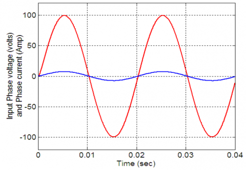
The Reference signal, offset signal, and resulting modulating signal are shown in Figure 4. The input side phase voltage and current are given to the three-phase matrix converter are shown in Figure 5. Finally, the output phase voltage and current obtained at the output side are shown in Figure 6.
Figure 3. Switching signals for s11, s12 and s13
Figure 4. The reference signal, offset signal, and resulting modulating signal
Figure 5. The input phase voltage and current
Figure 6. The output phase voltage and current
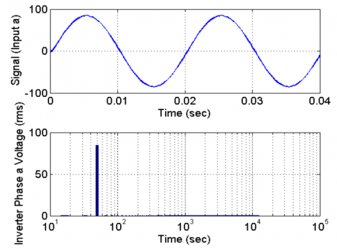
Figure 7. Harmonics view in phase ‘a’ filtered voltage at the output side
Above Figure 7 indicate the harmonics view of the voltage at the output side for phase ‘a’. The harmonics analysis indicates that voltage at the output side has a fundamental ingredient having a frequency of 50 Hz and its magnitude is 84.6 volt which is the peak value. Its total harmonic distortion (THD) value is 0.67% and the weighted total harmonic distortion (WTHD) value is 0.47%. These values indicate that the nature of output is perfectly sine wave.
2.2 Space vector pulse width modulation
The SVPWM has a great place among all other modulation methods since it decreases the count of commutations by efficient use of input voltage, also it can maintain input power factor in a good range so that the grade of electrical power remains best [11, 12]. According to the space vector illustration, the SVM produces the required reference signal by taking the resultant of two adjoining vectors and the vectors having zero state [13]. This method has the potential to generalize the switching problem of matrix converters.
Matrix converters have two types of configurations which are direct type and indirect type. Direct SVM has the advantages of easy implementation and simple switching process also it does not have DC-link [14].
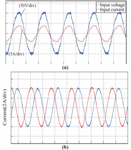
The indirect method can control the load side frequency, the magnitude of input side current as well as the power factor of the input side [7, 15]. In this method, we can interconnect the switching process of both the stages inverter side and rectifier side so it is possible here to consider both sides at the same time [16]. In Figure 8 the practical results are shown for SVM of indirect matrix converters. In Figure 8(a) the matrix converter input waveform of V and I and Figure 8(b) the waveform of output-side I am shown. Also, it shows that in the SVM method the waveforms of current and voltages are pure sine waves.
Figure 8. (a) The waveform of Input side voltage and current time (10ms/div); (b) The waveform of Output current time (10ms/div)
2.3 Time equivalent space vector pulse width modulation method
In this paper, a new modulation method called time equivalent space vector PWM [17] is implemented in a three-phase to three-phase matrix converter.
In this method switching signal for each converter, the leg is produced by utilizing the sampled reference voltages to produce sine wave output. The sampling of the reference voltage is done at a finite time which should be equivalent to the switching span.
After the sampling process, the voltage magnitude is transformed into an equivalent time signal. Each converter leg switching span is found out by summing the offset time to these signals. By adding offset centralizing of operative switching signals inside the switching span is done. The procedure of proposed time equivalent space vector PWM is stated stepwise.
where, Vx; x=a,b,c; is the sampling magnitude of phase voltages taken as reference and Ts is the time of converter switching. Tx; x=a,b,c; are known as time equivalents of the sampling magnitude of phase voltages taken as reference.
2.3.1 Algorithm of the proposed time equivalent space vector PWM
I. Firstly Sampling of reference phasevoltages Va, Vb & Vc, is done for each switching span Ts.
II. Secondly calculate the equivalent times T1, T2& T3 given by expression, Txs = Vxs* Ts/ Vdcwhere x = a, b and c.
III. In third step calculate Toffset;
Toffset=TS/2-(T max+T min)/Vdc
IV. In the fourth step the converter leg switching times are calculated by Tgx=Tx+Toffset; x=a, b and c.
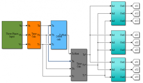
The proposed time equivalent space vector PWM simulation model is given in Figure 9 and its subsystem is given in Figure 10. Subsystem shown in Figure 10 actually represent the switching generation model which generate the switching signals.
Figure 11 is showing the output phase voltage using the time equivalent modulation method in a three-phase to three-phase matrix converter and Figure 12 is showing the THD (Total harmonic distortion) which is very low in comparison to other methods.
Figure 9. Simulation model of proposed time equivalent modulation scheme
Figure 10. The subsystem of the Simulation model of proposed time equivalent modulation scheme
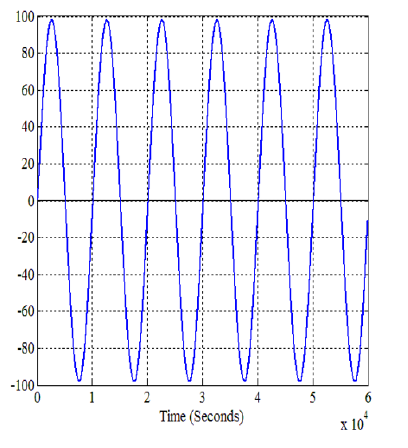
Figure 11. Output phase voltage
Figure 12. Harmonic spectrum of output voltage
The performance comparison between different modulation methods can be given based on the output voltage and current magnitude and waveform nature. The main indicator of performance is the THD based on which we can say that the lowest THD has the lowest harmonics so overall the lowest THD and pure sine wave nature of output waveform are two main parameters based on which we give the comparative analysis.
In Figure 13(a) and 13(b), comparative analysis of carrier-based modulation scheme and time equivalent space vector pulse width modulation scheme is shown which shows that the time equivalent space vector pulse width modulation scheme has lowest THD and also higher magnitude in comparison to a carrier-based modulation scheme. In Figure 13(a) and 13(b), comparative analysis of carrier-based modulation scheme and time equivalent space vector pulse width modulation scheme is shown which shows that the time equivalent space vector pulse width modulation scheme has lowest THD and also higher magnitude in comparison to a carrier-based modulation scheme.
Figure 13. a. Carrier-based PWM; b. Proposed time equivalent PWM
Matrix converter is a single-stage AC to AC converter so it has a huge scope of research as compared to other converters. In this paper advantages of matrix converters over traditional two-stage ac to ac, converters can be seen in various modulation schemes. Since MCs do not need a DC-link structure so the efficiency of these converters is much more and also the size of the converter becomes compact. This paper reviews the various research works on MCs and their various control methods with recent developments. Various modulation schemes are covered and compared with their performances.
It has come to an end that all discussed modulation schemes have their own merits and demerits. Time equivalent space vector PWM is more flexible as compared to others and also it is simpler. SVM is more efficient as compared to the carrier-based approach. But as per comparative analysis based on output and THD the proposed time equivalent space vector PWM is best.
[1] Gyugyi, L., Pelly, B.R. (1976). Static Power Frequency Changers: Theory, Performance, and Application. John Wiley & Sons.
[2] Daniels, A.R., Slattery, D.T. (1978). New power convertor technique employing power transistors. In Proceedings of the Institution of Electrical Engineers, 125(2): 146-150. https://doi.org/10.1049/piee.1978.0038
[3] Venturini, M., Alesina, A. (1980). The generalised transformer: A new bidirectional, sinusoidal waveform frequency converter with continuously adjustable input power factor. 1980 IEEE Power Electronics Specialists Conference, Atlanta, GA, USA, pp. 242-252. https://doi.org/10.1109/PESC.1980.7089455
[4] Venturini, M. (1980). A new sine wave in sine wave out, conversion technique which eliminates reactive elements. Proc. Powercon7, pp. E3/1-E3/15.
[5] Deivasundari, P., Jamuna, V. (2011). A Z-source single phase matrix converter with safe commutation strategy. International Journal of Energy and Environment, 2(3): 579-588.
[6] Neft, C.L., Schauder, C.D. (1988). Theory and design of a 30-hp matrix converter. Conference Record of the 1988 IEEE Industry Applications Society Annual Meeting, Pittsburgh, PA, USA. pp. 934-939. http://dx.doi.org/10.1109/28.137434
[7] Huber, L., Borojevic, D. (1995). Space vector modulated three-phase to three-phase matrix converter with input power factor correction. IEEE Transactions on Industry Applications, 31(6): 1234-1246. https://doi.org/10.1109/28.475693
[8] Malekjamshidi, Z., Jafari, M., Zhu, J., Xiao, D. (2019). Bidirectional power flow control with stability analysis of the matrix converter for microgrid applications. International Journal of Electrical Power & Energy Systems, 110: 725-736. https://doi.org/10.1016/j.ijepes.2019.03.053
[9] Zhou, S., Rong, F., Sun, W., Huang, S., Wu, Q. (2020). AC/AC grid connection of six-phase wind power generator based on enneagon MMC converter. International Journal of Electrical Power & Energy Systems, 118: 105810. https://doi.org/10.1016/j.ijepes.2019.105810
[10] Kumar, A. (2012). Control of three-phase to three-phase matrix converter using carrier based scheme. International Conference on Emerging Trends in Engineering and Technology College of Engineering, Teerthanker Mahaveer University
[11] Casadei, D., Serra, G., Tani, A., Zarri, L. (2002). Matrix converter modulation strategies: A new general approach based on space-vector representation of the switch state. IEEE Transactions on Industrial Electronics, 49(2): 370-381. https://doi.org/10.1109/41.993270
[12] Gao, F., Iravani, M.R. (2007). Dynamic model of a space vector modulated matrix converter. IEEE transactions on power delivery, 22(3): 1696-1705. https://doi.org/10.1109/TPWRD.2007.899609
[13] Klumpner, C., Lee, M., Wheeler, P. (2006). A new three-level sparse indirect matrix converter. IECON 2006-32nd Annual Conference on IEEE Industrial Electronics, Paris, France, pp. 1902-1907. https://doi.org/10.1109/IECON.2006.347958
[14] Luca, Z. (2007). Control of Matrix Converters. Ph.D. dissertation. Italy: University of Bologna.
[15] Friedli, T., Kolar, J. W., Rodriguez, J., Wheeler, P.W. (2011). Comparative evaluation of three-phase AC-AC matrix converter and voltage DC-link back-to-back converter systems. IEEE Transactions on Industrial Electronics, 59(12): 4487-4510. https://doi.org/10.1109/TIE.2011.2179278
[16] Cha, H.J., Enjeti, P.N. (2003). An approach to reduce common-mode voltage in matrix converter. IEEE Transactions on Industry Applications, 39(4): 1151-1159. https://doi.org/10.1109/TIA.2003.814554
[17] Gupta, S.K., Khan, M.A., Iqbal, A., Husain, Z. (2012). Comparative analysis of pulse width modulation schemes for five phase voltage source inverter. 2012 Students Conference on Engineering and Systems, Allahabad, India, pp. 1-6. https://doi.org/10.1109/SCES.2012.6199036