Noureddine Benbaha* | Fatiha Zidani | Abdelhak Bouchakour | Seif Eddine Boukebbous | Mohamed Said Nait-Said | Hachemi Ammar | Salah Bouhoun
© 2021 IIETA. This article is published by IIETA and is licensed under the CC BY 4.0 license (http://creativecommons.org/licenses/by/4.0/).
OPEN ACCESS
Since the first installations of solar systems, PV pumping systems have taken a large part in solar energy projects and nowadays they belong to the most significant applications of photovoltaic energy. With the increased use of the PV water pumping systems, sizing and selecting suitable design is essential in order to achieve the most reliable and economic operation for this type of systems. On a real well of 25 m head in desert and semi-arid climate in Sebseb site, Ghardaia, Algeria, a typical PV pumping system for irrigation purpose is installed in order to evaluate its performance under outdoor conditions. Therefore, three PV array configurations are considered to supply a novel version of centrifugal solar pump PS2 C-SJC 12 with a storage tank. The pumped water is used to irrigate 3 hectares of agricultural land. Oversized PV array increases its output power at weak solar irradiance. However, too much oversize will negatively affect the economic reliability. With respect to the wide normal operating range of centrifugal pump, three oversized PV configurations by 4%, 46% and 78% are examined. The experimental results show that PV pumping system can successfully start at low solar radiation 86.21 W/m2 and the optimum performances are obtained with the oversizing of 46%.
water pumping system, photovoltaic array configurations, experimental evaluations, desert environment, efficiency, centrifugal pump
The growth of world’s population and economic development increases directly the demand of energy in future years. Conventional energy resources are the most causes of environmental pollution and global warming. For that, renewable energy resources which are accessible in the world can contribute to the balance between huge energy demand and climate change [1].
Algeria is committed to stabilize and reduce greenhouse gas emissions after the ratification of the Kyoto Protocol in 1997 [2]. The greatest renewable energy sources in Algeria that can reduce the impact of global warming, we can cite, solar, biomass, wind, geothermal, and fuel cells energy [3, 4]. They are sustainable, non-polluting and economically viable energies [5]. Solar energy is free, clean and inexhaustible resource that can be used in various applications: electrification, pumping [6]. Electricity produced by the national electricity grid may not reach some remote areas; therefore, solar energy sources are becoming critical especially in developing countries, where they can be used for lighting as well as for irrigation and water pumping [6]. Due to its geographical location, Algeria has one of the highest solar potentials in the world [7]. In a clear day, incident solar radiation can reach 1000 W/m² [8, 9]. The Saharan climate reigns over 84% of its surface area [10], Algeria is therefore considered an ideal place for this type of applications. In this context, especially in desert areas, photovoltaic water pumping systems are suitable for water supply because of its distance from the “conventional” electricity grid, in other hand, the used diesel pumping systems can contribute to many difficulties, such as: air pollution, high maintenance and repair costs, and transporting the fuel for long distances through desert roads in extreme weather conditions (movable sands and high temperatures can exceed 45°C). The pumped water can be used in many applications, such as household use, irrigation and livestock supply. It is used during the day and the surplus stored in reservoirs, making the water available at night or on cloudy days; so, tanks are used instead of batteries [10, 11].
Research and current status of various aspects of SPVWPS have been carried out by review papers [12-15]. Due to the great importance of the motor in the PV pumping chain to generate the appropriate electromechanical power conversion [16], recently, regarding the suitable type of engine, a large number of studies have been conducted such as brushless DC motor (BLDC) [17, 18], permanent magnet (PM) motor [19-21], switched reluctance motor (SRM) [22] and the induction motor (IM) [23]. However, due to its significant characteristics such as high efficiency, high power density, quick acceleration capability and strong starting torque at low input power [24, 25], the brushless permanent magnet motor is considered an appropriate matching for stand-alone PV pumping systems.
Concerning the used converter (DC/DC or DC/AC) which depends on the motor types, a number of MPPT techniques are presented to optimize and enhance the energy efficiency [26-28]. In other hand, Meunier et al. [29-32] show important works about sizing, feasibility and technical-economic evaluation of PV water pumping systems for farm irrigation and domestic uses in remote areas. According to a critical analysis based on recent research works in term of PV water pumping performance improvements. Odeh et al. [33] developed and validated a typical installation in Jordan where the daily water output of 30 m3 and 100 m3 are obtained with variation of PV generator between 2 and 10 kWp. They stated that, subsystem efficiency and water output volume improve but PV efficiency decreases, when PV array size is increased. With a helical pump installed in a deep well (80 m), Benghanem et al. [34] select an optimum PV configuration which provides a maximum energy in Madinah site. They show that, two suitable PV array configurations (6S_4P) and (8S_3P) are chosen to supply the optimum electrical power. Benghanem et al. [35] examine the effect of different pumping head (50 m, 60 m, 70 m and 80 m) to evaluate the real performance of the system. According to the authors for 80 m, SQF submersible pump is suggested because it presents best system efficiency. In an artificial well, Tiwari et al. [36] determine through different configurations the adequate solution to supply a DC helical pump under real conditions of Nagpur. Based on maximum daily average of pumped water (24374 L), they found that two configurations (4S X 2P) and (5S X 2P) are appropriate. In other hand, an experiment analyze was done for 40, 60, 80 and 100 m of head in the ref. [37]. They obtained that the optimal efficiency is reached under total head of 100 m. Four hybrid PV pumping configurations (direct, with supercapacitor, with battery and battery-supercapacitor) are analyzed by Das and Mandal [38]. For that, a small scale prototype with centrifugal pump is tested experimentally for 2 m and 3 m of head. According to the results, firstly; a maximum pumped water of 2964 L/day with 2 m is given by battery bank. In second case, the supercapacitor offers highest instantaneous efficiency and provides a maximum of 1826 L/day. Matam et al. [39] proposed an algorithm and control technique for adequate operation of reconfigurable PV pumping system to improve the response under several conditions. By using four panels of 40 Wp operate the pump under all conditions (high head, partial shading). The adopted switched controller produced 32.54% additional energy and improved by 2 hours pumping time. An experimental work has been conducted to determine the best configuration of direct PV water pumping system at four heads 20, 30, 40, and 50 m in the Ref. [40]. They can be concluded that (5S × 2P) and (8S) configurations provide respectively maximum water in winter and summer at all head.
Based on economic and agricultural program adopted by the Algerian government, the water supply is one of the important factors used to ensure the citizen preoccupations. Furthermore, our project aim is to realize typical installations in various pumping heads at Ghardaia territory, which is characterized by daily solar energy of 7448 Wh/m² and an average sunshine over than 3200 hours per year. This work is realized at Sebseb location, which is an area harnessed with fertile soil and wonderful climate for the production of vegetables and fruits, especially tomatoes, dates and peanuts. On a real well of 25 m head, a PV water pumping system with hydraulic storage has been installed. The purpose of this study is to monitored and evaluate the effectiveness of the system under three various PV array configurations. A suitable comparative discussion is conducted to determine the appropriate configuration and to improve the overall system efficiency.
2.1 Geographical location of the site
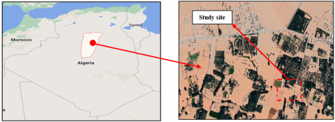
Sebseb is a commune in Ghardaia city in Algeria, located 660 km south of Algiers. It has a hot desert climate, with extremely hot summers and mild winters. In this area, electricity may not reach some agricultural regions and some spread communities. Installing stand-alone photovoltaic pumping system in this area will enable these communities to improve their livelihoods by irrigating crops and supplying electricity. Figure 1 shows the geographical location of the town of Sebseb at latitude 32° 51' North and longitude 3° 20' East, with an altitude of 470 m above sea level.
2.2 Photovoltaic water pumping system
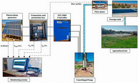
Our PV water pumping system consists of monocrystalline PV modules of 130 Wp each and inclined at 32° to the south, connection and protection box, monitoring system, storage tank and PS2-1800 C-SJ5-12 Lorentz kit which composed of: permanent magnetic sensorless brushless direct-current motor (PMSDCM), PS2 controller with MPPT and centrifugal pump of 12 turbines with maximum flow rate of 7.6 m3/h. Figure 2 shows the overall structure of the used PV installation. Table 1 shows the PV module parameters.
Figure 1. Satellite view of Sebseb site, Ghardaia (Algeria)
Figure 2. Overall structure of the PV water pumping installation
Table 1. Characteristics of I-130 s/24 module
|
Parameters |
Value |
|
Pmp (W) |
130 |
|
Voc (V) |
43.2 |
|
Isc (A) |
3.95 |
|
Vmp (V) |
34.6 |
|
Imp (A) |
3.76 |
|
Panel Efficiency |
10.1% |
|
Fill Factor |
67.6% |
|
Power Tolerance |
-10.00% ~ 10.00% |
2.3 Description of CMP subsystem kit
The used PS2-1800 C-SJ5-12 subsystem Lorentz kit is mainly composed by: (1) PS2 controller with MPPT, (2) Centrifugal pump with 12 turbines driven by permanent magnetic brushless DC motor.
The Lorentz PS2 controller transforms the direct voltage from the panels to the ECDRIVE motor, with three-phase alternating voltage and variable frequency. This converter is equipped with maximum power point tracking control (MPPT) wish is used to follow and extract the optimal power. For that, a sun sensor is installed in a same tilted plane (32°) of the PV generator structure. Table 6 (appendix) shows the global technical characteristics of the PS2-1800 controller.
The operation principle of a centrifugal pump consists in moving the liquid from the suction (low pressure) to the discharge (high pressure). Its process requires a motor that produces its rotation. Sizing of centrifugal pump involves three parameters: pumping head (H), pump capacity (Q), and shaft power which are functions of the impeller speed. The hydraulic power is given by:
$P_{h y d}=\frac{\rho \cdot g \cdot Q \cdot H}{\eta_{C M P}}$ (1)
where, g is the gravity acceleration and ρ is the water density.
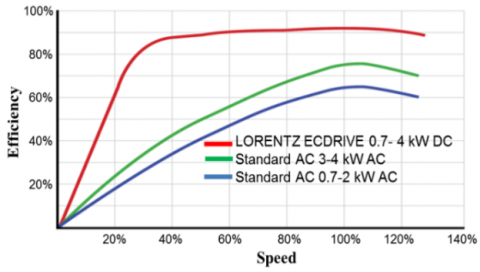
Recently, the interest in the brushless permanent magnet motors is increasing because of their significant characteristics such as high-power density and strong torque [24, 25]. Furthermore, their operation at low input power allows a smooth starting [25]. Thus, they are considered a perfect match for stand-alone PV pumping system. In our work, the called ECDRIVE is a three-phase permanent magnet brushless DC motor driven by a sensor-less electronically commutating controller [41]. Among its special features, for small scale power that is less than 4 kW, it operates with a higher efficiency throughout the whole operating range compared to AC motor where its maximum efficiency is only reached in a narrow operating band (Figure 3). In our application, a centrifugal pump driven by the mentioned motor (ECDRIVE) has been installed in a well with total head of 25 m.
Figure 3. Characteristics of the ECDRIVE motor [41]
2.4 Data acquisition system
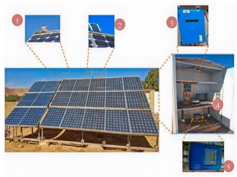
Real-time measurements of the various electrical and hydraulic parameters are the crucial point for performance evaluation of the installed PV pumping system at Sebseb. Consequently, a monitoring system for the different magnitudes was installed (Figure 4); consisting of: pyranometer, PS2-1800 controller, Agilent 34970A data logger and flow meter.
During each scan of 2 min, the instantaneous values of solar radiation intensity, ambient temperature, DC voltage, DC current and pumped water flow rate were stored into the computer through Agilent 34970A data logger. Figure 4 shows the measurement components.
Figure 4. Main measurement equipment such as: (1) Pyranometer, (2) sun sensor, (3) Lorentz PS2 controller, (4) Computer and data logger Agilent 34970A, (5) water flow meter
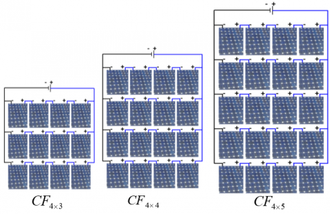
In order to achieve a high performance of the PV water pumping system under real outdoor conditions installed in a real well of 25 m dynamic head. A reconfigurable PV power supply is adopted; in fact, the system was examined under three different configurations during three sunny days, October 2020, namely: $C F_{4 \times 3}$ (Ns=4, Np=3), $C F_{4 \times 4}$ (Ns=4, Np=4), $C F_{4 \times 5}$ (Ns=4, Np=5) (Figure 5) (Table 2). Note that, in terms of number of string, the $C F_{4 \times 4}$is composed of 4 strings ($C F_{4 \times 4}=C F_{4 \times 3}+4^{\text {th }}$ string) and $C F_{4 \times 5}$ with 5 strings (so, $C F_{4 \times 5}=C F_{4 \times 3}+4^{\text {th }}$ string $+5^{\text {th }}$ string).
Table 2. Specification of the proposed PV array configurations
|
PV Array connections |
Manufacturer’s data under STC |
A (m2) |
||
|
Imp(A) |
Vmp(V) |
PPV(Wp) |
||
|
4S×3P |
11.28 |
138.4 |
1560 |
12.64 |
|
4S×4P |
15.04 |
138.4 |
2080 |
16.86 |
|
4S×5P |
18,8 |
138.4 |
2600 |
21.07 |
For each configuration, an equivalent data of the PV generator current and voltage, flow rate, irradiance and ambient temperature are acquired and used to calculate the available PV power, consumed power and controller-motor-pump subsystem efficiency by using the following expressions.
$P_{\text {Avail }}=G \times A \times \eta_{P V-n o m}$ (2)
Figure 5. Proposed PV panel configurations
$P_{h y d}=\rho \times g \times Q \times H$ (3)
$\eta_{C M P}=\frac{P_{h y d}}{I_{P V} \times V_{P V}}=\frac{\rho \times g \times Q \times H}{I_{P V} \times V_{P V}}$ (4)
$V=\int_{D a y} Q . d t$ (5)
4.1 Performance evaluations at low solar radiation (start and end of the pumping)
The tests were performed during the October month and throughout the day, starting from low irradiance in the morning to high irradiance in the midday and down to low irradiance in the evening. For each test, measurements of the PV generator current and voltage, flow rate, irradiance and ambient temperature are recorded. Other performances will be calculated such as the different efficiencies. Table 3 shows the instantaneous measurements at the start and end of pumping for the three different configurations.
Table 3. Instantaneous measurements at the start and end the pumping for different configurations
|
Start/End pumping |
Time (h:mn) |
G (W/m2) |
Ambient Temper. (°C) |
DC Voltage (V) |
DC Current (A) |
Consumed power (W) |
Flow (m3/h) |
|
$C F_{4 \times 3}$ |
|||||||
|
At Start pumping |
07:32 |
86.21 |
23.13 |
115.11 |
0.62 |
71.94 |
0.11 |
|
At end pumping |
17:32 |
109.48 |
33.57 |
95.63 |
0.88 |
84.15 |
0.13 |
|
$C F_{4 \times 4}$ |
|||||||
|
At Start pumping |
07:25 |
89.06 |
24.84 |
98.59 |
1.19 |
117.32 |
0.40 |
|
At end pumping |
17:31 |
82.99 |
34.50 |
100.85 |
0.80 |
80.68 |
0.08 |
|
$C F_{4 \times 5}$ |
|||||||
|
At Start pumping |
07:26 |
133.09 |
15.66 |
116.14 |
0.91 |
105.68 |
0.28 |
|
At end pumping |
17:38 |
100.81 |
33.861 |
100.13 |
0.5 |
50.06 |
0.14 |
After the sunrise, during early morning at around 07:32 AM and only with 86.21 W/m2 of irradiance, the system can start pumping with 0.11 m3 / h for the configuration $C F_{4 \times 3}$when the sufficient extracted power (71.94 W) is reached with starting current of 0,62 A. The system ends pumping around 17:38 with a flow rate of 0.14 m3 / h for the configuration $C F_{4 \times 5}$ with a minimum power of 50.06 W and a current of 0.5A. This proves the robustness of the permanent magnet DC motor for PV water pumping systems. The temperature influence on PV voltage and also generated current with less effect, in $C F_{4 \times 5}$ configuration start pumping; at 15.66°C and 133.09 W/m², the voltage and current are 116.14 V, 0.91 A respectively. Moreover, for 24.84°C (≈25°C which is the STC temperature) at only 89.06 W/m²; the obtained voltage and current are 98.59 V, 1.19 A, as a result; the flow rate pumped water is 0.4 m3/h correspond to $C F_{4 \times 4}$ configuration.
4.2 Evolution of the pump consumed power
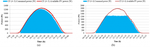
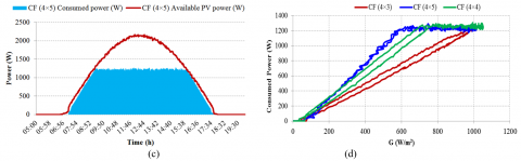
Figure 6 shows the available output power of the PV generator and the power consumed by the motor pump for the three studied configurations. The first configuration reaches its maximum power only with an irradiance of 1000 W/m². So it has a unique power limited point at about (1000 W/m² and 1230W). Therefore, the available power of the PV generator is less than the consumed power by the motor pump. The second configuration attaints its maximum power only with an irradiance of 750 W/m² and 1226 W, approximately at 10:00. The third configuration arrives at its maximum power only with an irradiance of 600 W/m² and 1220 W, approximately at 9:50. The power consumption is limited to its maximum value correspond to the hydraulic operating point which characterized by maximum flow rate and imposed pumping head (25m). In this state (Table 4), the size of PV array configuration has a major impact on the duration of the saturation power ($C F_{4 \times 3}$ has only 36mn, $C F_{4 \times 4}$ has 5h8mn and $C F_{4 \times 5}$ has 6h32mn), where a large quantity of water is pumped in this region, except; loss of some energy, which drop down the total efficiency for $C F_{4 \times 4}$ and $C F_{4 \times 5}$ configurations. Figure 6 d summarizes the consumption powers for the three studied configuration with solar radiation. The PV external measured voltages and currents are illustrated in (Figure 7). For the first time interval with low irradiance, a small PV voltage overtaking appears caused by the MPPT controller at pump starting up (Figure 7 a). For the second time interval with high irradiance and after reaching the maximum power, the PV voltages are quasi-equal and follow the operating point, in other hand; the currents increased gradually according to the solar radiation and array configurations (at the morning, the $C F_{4 \times 5}$current is rapidly increasing compared to the others, contrary at the afternoon, the $C F_{4 \times 3}$ current reduced before the others) (Figure 7 b). For the third time interval with low irradiance in the evening, the voltage and current of the PV generator decreases with the decrease in solar radiation. When the current reaches its maximum limit, the controller compensates its reference power by reducing the PV voltage (from 11h to 15h) for $C F_{4 \times 3}$ configuration (Figure 7 b). In limited mode, for the $C F_{4 \times 4}$ and $C F_{4 \times 5}$configurations, the currents are imposed by the operating point of the motor pump, so, the voltages are increased to reimburse the consumed power (Figure 7 a). According to the times 14h: 40 for the $C F_{4 \times 4}$ configuration and at 15h: 50 for the $C F_{4 \times 5}$configuration, the voltages return to MPPT mode because the generated current is lower than the imposed one (Figure 7 a).
4.3 Benefit pumping water per day
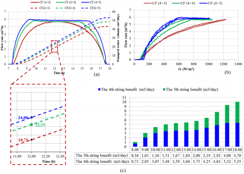
The performance of the three different PV pumping system configurations is illustrated by the flow rate variation, pumped water volume per day and the benefit of 4th and 5th strings in terms of the amount of water pumped per day (Figure 8). The measured instantaneous flow rate increases with increasing in solar radiation.
Table 4. Duration of pump saturation power for different configurations
|
CF |
Time of Starting Saturation (h:mn) |
Time of Ending Saturation (h:mn) |
Duration Saturation (h) |
|
$C F_{4 \times 3}$ |
12:08 |
12:44 |
36mn |
|
$C F_{4 \times 4}$ |
9:39 |
14:47 |
5h and 8mn |
|
$C F_{4 \times 5}$ |
9:14 |
15:46 |
6h and 32mn |
Figure 6. Available PV and powers, (a) $C F_{4 \times 3}$ , (b) $C F_{4 \times 4}$, (c) $C F_{4 \times 5}$ configurations, (d) Consumed power for the three configurations
Figure 7. Measured (a) PV voltage and (b) PV current for the three configurations
For the first configuration $C F_{4 \times 3}$, the flow rate reaches its maximum 5.7 m3/h at 12h, and the obtained pumping volume per day is 43 m3/day (Figure 8 a). For the two other configurations ($C F_{4 \times 4}$,$C F_{4 \times 5}$), the flow rate reaches its maximum 5.8 m3/h and 6 m3/h at 9:40 and 9:10 respectively, the pumped water volume is 48.37 m3/day and 53.07 m3/day for each ones Figure 8 (a) and (b). It is clear that the time to reach the maximum flow for the ($C F_{4 \times 4}$, $C F_{4 \times 5}$) configurations is important than that of the $C F_{4 \times 3}$ configuration. The hourly water benefit of $C F_{4 \times 4}$and $C F_{4 \times 5}$ configuration is illustrated in Figure 8 (c). The quantity of water pumped per day for the $C F_{4 \times 5}$ configuration is greater, because it is composed of 20 modules with a peak power of 2600 Wp compared to 2080 Wp and 1560 Wp for the configurations $C F_{4 \times 4}$and $C F_{4 \times 3}$ respectively. It's clear that the contribution of 5th string is smaller than the 4th string compared to the added cost.
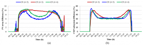
4.4 Efficiency of the three configurations
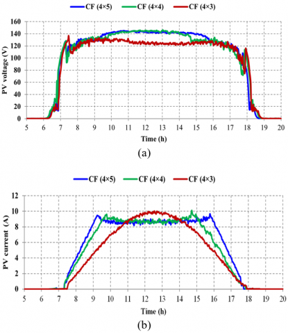
The efficiencies of the PV array and CMP subsystem for the three configurations are illustrated in Figure 9 and Table 5. The results can be spread over three-time intervals as follows:
- For the $C F_{4 \times 3}$configuration: (1) From 07:41 to 11:00; (2) From 11:00 to 13:55; (3) From 13:55 to 17:40.
- For the $C F_{4 \times 4}$and $C F_{4 \times 5}$configurations: (1) From 07:41 to 9:30; (2) From 9:30 to 15:45; (3) From 15:45 to 17:40.
During the first time interval, the PV output power is less than the required motor pump power and the CMP efficiencies reached their maximum values of 51.54%, 50.60% and 54.71%, for $C F_{4 \times 3}$, $C F_{4 \times 4}$ and $C F_{4 \times 5}$, respectively. For the second time interval, the CMP efficiencies drop down to 30% after the motor pump had reached the maximum hydraulic operating point. For the final time interval, the CMP efficiencies increase with same allure of the first time interval up to their maximum values and after they decrease rapidly with the fall of solar radiation in the evening.
Similarly, for the efficiency curves of PV array. The efficiencies are increased up to their maximum values for the first time interval. Then, for the second time interval, they decrease after the motor pump had reached the maximum hydraulic operating point for the $C F_{4 \times 4}$ and $C F_{4 \times 5}$ configurations, then, they increase up to their maximum values again with the decrease in solar radiation.
The $C F_{4 \times 3}$configuration operates with its maximum efficiency throughout the day since; it doesn't reach their maximum operating point except at midday with strong irradiation. But we notice that, there is a reduction in efficiency from 10.31% (at 11:15) to 8% (at 17:00) caused by the increase in the temperature of the PV cell. Also, the average PV array efficiency (8.45% compared to 10.1% in STC conditions) is higher than the other configurations because there is a smaller saturation time (36mn). As a result, the $C F_{4 \times 3}$ configuration offers better performance compromise between water volume pumped and efficiency.
Figure 8. (a) Flow rate and daily pumped volume during the time of day, (b) Instantaneous flow rate according to the irradiation, (c) Evaluation of 4th and 5th strings benefit with reference to the $C F_{4 \times 3}$ configuration
Table 5. Average and maximum efficiencies of CMP subsystem and PV array
|
Different configurations |
Water volume m3/day |
Average PV array efficiency (%) |
Max. PV array Efficiency (%) |
Average CMP subsystem Efficiency (%) |
Max. CMP subsystem Efficiency (%) |
|
$C F_{4 \times 3}$ |
43 |
8.45 |
10.31 |
37.33 |
51.54 |
|
$C F_{4 \times 4}$ |
48.37 |
7.48 |
10.65 |
34.66 |
50.60 |
|
$C F_{4 \times 5}$ |
53.07 |
6.90 |
10.03 |
35.20 |
54.71 |
Figure 9. Efficiency curves of (a) CMP subsystem and (b) PV array for the three configurations
The oversizing in PV array is a crucial factor to improve the effeteness of the PV water pumping system. For that, the experimental results based on three oversized PV arrays of 4%, 46% and 78% showed that the system can successfully start at low solar radiation 86.21 W/m2 and the optimum performances are obtained with the oversizing of 46%.
This paper deals with a comparative assessment of standalone PV water pumping system installed on real well in a desert climate (Sebseb in Ghardaia, Algeria) for irrigation and livestock watering purposes. Real time pumping experiments through PV array configurations have been carried out in order to evaluate their technical performances in terms of instantaneous flow rate, daily pumped water volumes, power consumption, and the global efficiency of the main system components.
The distinct features of the studied PV water pumping system were verified, as a result, the system can successfully start pumping at low solar radiation of 86.21 W/m2 (7h:32, 0.11 m3/h, 115.11 V, 0.62 A). Once the pump reaches its maximum power, the water flow arrives at the maximum value correspond to the hydraulic operating point. The PV array configuration ($C F_{4 \times 3}$) gives highest daily average efficiency for both the CMP subsystem and PV array, however, the pumped water volume can be insufficient especially during cloudy days, event partial shade and dust.
Thus, a reconfigurable PV array panels have been adopted. When a string is added to get ($C F_{4 \times 4}$) configuration, the water volume pumped increases by 12.4% per day. Furthermore, the adding of second string to get ($C F_{4 \times 5}$), increases the water volume only 10.9%. It is crucial to note that the permanent rising of PV strings is limited by the decline of the benefit water volume and the increase in the total cost of the installation.
Three oversized PV arrays of 4%, 46% and 78% compared to the measured maximum power operating point are investigated. The experimental results showed that the system can successfully start at low solar radiation 86.21 W/m2 and the optimum performances are obtained with the oversizing of 46%.
The paper especially focused on technical side of the PV pumping system, in order to complete this work, a yearly experimental evaluation under various meteorological conditions (irradiation, temperature, dust, aging and shading) and economical study will be realized in future research direction.
|
PV |
Photovoltaic |
|
CMP |
Controller-motor-pump subsystem |
|
SPVWPS |
Solar photovoltaic water pumping systems |
|
MPP |
Maximum Power Point |
|
G |
Global solar irradiance in the plane of the PV generator (W/ m2) |
|
CF |
PV array configuration |
|
S |
Modules in series |
|
P |
Modules in parallel |
|
$C F_{4 \times 3}$ |
Configuration 4S×3P |
|
$C F_{4 \times 4}$ |
Configuration 4S×4P |
|
$C F_{4 \times 5}$ |
Configuration 4S×5P |
|
$I_{S C}$ |
Short circuit DC current of the PV module at STC [A] |
|
$P_{m p}$ |
DC maximum power of the PV generator at STC [W] |
|
$V_{D C}$ |
Measured DC voltage of the PV generator [V] |
|
$V_{m p}$ |
Optimal voltage of the PV generator at STC [V] |
|
$V_{o c}$ |
Open circuit voltage of the PV module at STC[V] |
|
$I_{m p}$ |
Optimal current of the PV module at STC [V] |
|
$I_{s c}$ |
Short circuit current of the PV module at STC [V] |
|
$\eta_{P V-n o m}$ |
Efficiency of the PV generator at STC |
|
$P_{\text {Avail }}$ |
Available PV array power (W) |
|
$P_{\text {hyd }}$ |
hydraulic power (W) |
|
$P_{M P}$ |
Motor-pump subsystem efficiency (%) |
|
VPV |
Measured PV array voltage |
|
IPV |
Measured PV array current |
|
$\eta_{P V}$ |
Efficiency of the PV generator (%) |
|
$\eta_{C M P}$ |
Efficiency of the controller-motor-pump subsystem (%) |
|
A |
Active area of PV array (m2) |
|
g |
Gravity acceleration (9.81 m/s2) |
|
$\rho$ |
Water density (1000 kg/m3) |
|
$Q$ |
Measured water flow rate (m3/h) |
|
H |
Total pressure head (m) |
|
V |
Daily pumped water volume (m3/day) |
Table 6. Technical data of the used solar pump kit [41]
|
PS2-1800 controller technical data |
|
|
Power (max) |
1800 W |
|
Input voltage (max) DC Voc |
200 V |
|
Input current (max) |
14 A |
|
Output voltage PWM 3~ |
30 – 130 V |
|
Efficiency |
Max 98% |
|
ECDRIVE motor |
|
|
Power (max) |
1,8 kW |
|
Rated power |
1,7 kW |
|
Input voltage |
95 V |
|
Motor speed |
900...3300 rpm |
|
Efficiency |
Max. 92% |
|
Maintenance |
free |
|
Robustness |
No electronics in the motor |
|
Centrifugal pump |
|
|
Head max. |
70 m |
|
Flow rate max. |
7,6 m³/h |
|
Efficiency max. |
65% |
|
Number of stages |
12 stages |
[1] Kaya, F., Şahin, G., Alma, M.H. (2021). Investigation effects of environmental and operating factors on PV panel efficiency using by multivariate linear regression. International Journal of Energy Research, 45(1): 554-567. https://doi.org/10.1002/er.5717
[2] Bouraiou, A., Necaibia, A., Boutasseta, N., Mekhilef, S., Dabou, R., Ziane, A., Sahouane, N., Attoui, I., Mostefaoui, M., Touaba, O. (2020). Status of renewable energy potential and utilization in Algeria. Journal of Cleaner Production, 246: 119011. https://doi.org/10.1016/j.jclepro.2019.119011
[3] Brahim, B. (2019). Performance investigation of a hybrid PV‐diesel power system for remote areas. International Journal of Energy Research, 43(2): 1019-1031. https://doi.org/10.1002/er.4301
[4] Kaur, M., Dhundhara, S., Verma, Y.P., Chauhan, S. (2020). Techno‐economic analysis of photovoltaic‐biomass‐based microgrid system for reliable rural electrification. International Transactions on Electrical Energy Systems, 30(5): p.e12347. https://doi.org/10.1002/2050-7038.12347
[5] Khraief, N., Shahbaz, M., Mallick, H., Loganathan, N. (2018). Estimation of electricity demand function for Algeria: revisit of time series analysis. Renewable and Sustainable Energy Reviews, 82: 4221-4234. https://doi.org/10.1016/j.rser.2016.11.106
[6] Balali, M.H., Nouri, N., Rashidi, M., Nasiri, A., Otieno, W. (2018). A multi‐predictor model to estimate solar and wind energy generations. International Journal of Energy Research, 42(2): 696-706. https://doi.org/10.1002/er.3853
[7] Sahouane, N., Dabou, R., Ziane, A., Neçaibia, A., Bouraiou, A., Rouabhia, A., Mohammed, B. (2019). Energy and economic efficiency performance assessment of a 28 kWp photovoltaic grid-connected system under desertic weather conditions in Algerian Sahara. Renewable Energy, 143: 1318-1330. https://doi.org/10.1016/j.renene.2019.05.086
[8] Necaibia, A., Bouraiou, A., Ziane, A., Sahouane, N., Hassani, S., Mostefaoui, M., Dabou, R., Mouhadjer, S. (2018). Analytical assessment of the outdoor performance and efficiency of grid-tied photovoltaic system under hot dry climate in the south of Algeria. Energy Conversion and Management, 171: 778-786. https://doi.org/10.1016/j.enconman.2018.06.020
[9] Boukebbous, S.E., Djallel, K. (2017). New strategy control of bidirectional quazi z source inverter with batteries and supercapacitors energy storage in grid connected photovoltaic system. International Journal of Power Electronics and Drive Systems, 8(1): 335.
[10] Zaky, A.A., Ibrahim, M.N., Rezk, H., Christopoulos, E., El Sehiemy, R.A., Hristoforou, E., Kladas, A., Sergeant, P., Falaras, P. (2020). Energy efficiency improvement of water pumping system using synchronous reluctance motor fed by perovskite solar cells. International Journal of Energy Research, 44(14): 11629-11642. https://doi.org/10.1002/ er.5788
[11] Boukebbous, S., Kerdoun, D. (2017). Power control of grid connected photovoltaic system assisted by batteries and water pumping energy storage in desert location. International Journal of Renewable Energy Research, IJRER, 7(4): 2139-2150.
[12] Chandel, S.S., Naik, M.N., Chandel, R. (2015). Review of solar photovoltaic water pumping system technology for irrigation and community drinking water supplies. Renewable and Sustainable Energy Reviews, 49: 1084-1099. https://doi.org/10.1016/j.rser.2015.04.083
[13] Li, G., Jin, Y., Akram, M.W., Chen, X. (2017). Research and current status of the solar photovoltaic water pumping system–A review. Renewable and Sustainable Energy Reviews, 79: 440-458. https://doi.org/10.1016/j.rser.2017.05.055
[14] Muhsen, D.H., Khatib, T., Nagi, F. (2017). A review of photovoltaic water pumping system designing methods, control strategies and field performance. Renewable and Sustainable Energy Reviews, 68: 70-86. https://doi.org/10.1016/j.rser.2016.09.129
[15] Rawat, R., Kaushik, S.C., Lamba, R. (2016). A review on modeling, design methodology and size optimization of photovoltaic based water pumping, standalone and grid connected system. Renewable and Sustainable Energy Reviews, 57: 1506-1519. https://doi.org/10.1016/j.rser.2015.12.228
[16] Bouchakour, A., Brahami, M., Borni, A. (2017). Comparative study on photovoltaic pumping systems driven by different motors optimized with sliding mode control. International Journal of Engineering and Technology Innovation, 7(3): 201.
[17] Ammar, H., Benbaha, N., Boukebbous, S.E. (2017). P&O control of a photovoltaic pumping system to efficiency improvement using PSIM. In 2017 International Renewable and Sustainable Energy Conference (IRSEC) (pp. 1-5). IEEE. https://doi.org/10.1109/IRSEC.2017.8477404
[18] Singh, B., Kumar, R. (2016). Solar photovoltaic array fed water pump driven by brushless DC motor using Landsman converter. IET Renewable Power Generation, 10(4): 474-484. https://doi.org/10.1049/iet-rpg.2015.0295
[19] Murshid, S., Singh, B. (2019). Energy-efficient single-stage solar PV powered sensorless PMSM drive for water pumping. IET Renewable Power Generation, 13(13): 2267-2277. https://doi.org/10.1049/iet-rpg.2018.6205
[20] Antonello, R., Carraro, M., Costabeber, A., Tinazzi, F., Zigliotto, M. (2016). Energy-efficient autonomous solar water-pumping system for permanent-magnet synchronous motors. IEEE Transactions on Industrial Electronics, 64(1): 43-51. https://doi.org/10.1109/tie.2016.2595480
[21] Prabhakaran, K.K., Karthikeyan, A., Varsha, S., Perumal, B.V., Mishra, S. (2020). Standalone single stage PV-Fed reduced switch inverter based PMSM for water pumping application. IEEE Transactions on Industry Applications, 56(6): 6526-6535. https://doi.org/10.1109/TIA.2020.3023870
[22] Singh, B., Mishra, A.K. (2019). Performance analysis of a solar-powered water pumping using improved SIDO buck–boost converter. IET Power Electronics, 12(11): 2904-2911. https://doi.org/10.1049/iet-pel.2018.5448
[23] Koussaila, I., Lyes, K., Himour, K., Abdelhakim, D., Azeddine, H., Kaci, G., Fouad, B.M. (2020). Impact of polyphase induction motor on photovoltaic water pumping system. Journal Européen des Systèmes Automatisés, 53(6): 763-770. https://doi.org/10.18280/jesa.530602
[24] Krishnan, R. (2017). Permanent Magnet Synchronous and Brushless Dc Motor Drives. CRC Press.
[25] Chakkarapani, K., Thangavelu, T., Dharmalingam, K., Thandavarayan, P. (2019). Multiobjective design optimization and analysis of magnetic flux distribution for slotless permanent magnet brushless DC motor using evolutionary algorithms. Journal of Magnetism and Magnetic Materials, 476: 524-537. https://doi.org/10.1016/j.jmmm.2019.01.029
[26] Benbaha, N., Zidani, F., Nait-Said, M.S., Zouzou, S.E., Boukebbous, S., Ammar, H. (2018). dSPACE validation of improved backstepping optimal energy control for photovoltaic systems. In 2018 6th International Renewable and Sustainable Energy Conference (IRSEC) IEEE, pp. 1-6. https://doi.org/10.1109/IRSEC.2018.8702908
[27] Bouchakour, A., Borni, A., Brahami, M. (2019). Comparative study of P&O-PI and fuzzy-PI MPPT controllers and their optimisation using GA and PSO for photovoltaic water pumping systems. International Journal of Ambient Energy, pp. 1-12. https://doi.org/10.1080/01430750.2019.1614988
[28] Boukebbous, S.E., Kerdoun, D. (2015). Study, modeling and simulation of photovoltaic panels under uniform and nonuniform illumination conditions. Revue des Energies Renouvelables, 18(2): 257-268.
[29] Meunier, S., Quéval, L., Darga, A., Dessante, P., Marchand, C., Heinrich, M., Cherni, J.A., Elvire, A., Vido, L., Multon, B., Kitanidis, P.K. (2020). Sensitivity analysis of photovoltaic pumping systems for domestic water supply. IEEE Transactions on Industry Applications, 56(6): 6734-6743. https://doi.org/10.1109/TIA.2020.3013513
[30] Santos, D.O.S., Wanderley Sena, T.O.R.R.E.S., Pedro Ferreira, B.R.I.T.O., Ubaiara, A. (2021). A novel method to determine the optimal operating point for centrifugal pumps applied in photovoltaic pumping systems. Solar Energy, 221: 46-59. https://doi.org/10.1016/j.solener.2021.04.005
[31] Allouhi, A., Buker, M.S., El-houari, H., Boharb, A., Benzakour Amine, M., Kousksou, T., Jamil, A. (2019). PV water pumping systems for domestic uses in remote areas: Sizing process, simulation and economic evaluation. Renewable Energy, 132: 798-812. https://doi.org/10.1016/j.renene.2018.08.019
[32] López-Luque, R., Reca, J., Martínez, J. (2015). Optimal design of a standalone direct pumping photovoltaic system for deficit irrigation of olive orchards. Applied Energy, 149: 13-23. https://doi.org/10.1016/j.apenergy.2015.03.107
[33] Odeh, I., Yohanis, Y.G., Norton, B. (2006). Influence of pumping head, insolation and PV array size on PV water pumping system performance. Solar Energy, 80(1): 51-64. https://doi.org/10.1016/j.solener.2005.07.009
[34] Benghanem, M., Daffallah, K.O., Alamri, S.N., Joraid, A.A. (2014). Effect of pumping head on solar water pumping system. Energy Conversion and Management, 77: 334-339. https://doi.org/10.1016/j.enconman.2013.09.043
[35] Benghanem, M., Daffallah, K.O., Joraid, A.A., Alamri, S.N., Jaber, A. (2013). Performances of solar water pumping system using helical pump for a deep well: A case study for Madinah, Saudi Arabia. Energy Conversion and Management, 65: 50-56. https://doi.org/10.1016/j.enconman.2012.08.013
[36] Tiwari, A.K., Kalamkar, V.R. (2016). Performance investigations of solar water pumping system using helical pump under the outdoor condition of Nagpur, India. Renewable Energy, 97: 737-745. https://doi.org/10.1016/j.renene.2016.06.021
[37] Tiwari, A.K., Kalamkar, V.R. (2018). Effects of total head and solar radiation on the performance of solar water pumping system. Renewable Energy, 118: 919-927. https://doi.org/10.1016/j.renene.2017.11.004
[38] Das, M., Mandal, R. (2018). A comparative performance analysis of direct, with battery, supercapacitor, and battery-supercapacitor enabled photovoltaic water pumping systems using centrifugal pump. Solar Energy, 171: 302-309. https://doi.org/10.1016/j.solener.2018.06.069
[39] Matam, M., Barry, V.R., Govind, A.R. (2018). Optimized reconfigurable PV array based Photovoltaic water-pumping system. Solar Energy, 170: 1063-1073. https://doi.org/10.1016/j.solener.2018.05.046
[40] Sontake, V.C., Tiwari, A.K., Kalamkar, V.R. (2020). Experimental investigations on the seasonal performance variations of directly coupled solar photovoltaic water pumping system using centrifugal pump. Environment, Development and Sustainability, pp.1-19. https://doi.org/10.1007/s10668-020-00965-x
[41] LORENTZ, Performance curve of PS2 C-SJC 12 motor-pump kit. https://www.lorentz.de/products-and-technology/, accessed 04 January 2021.