Izzeddine Dilmi* | Abderrahmen Bouguerra | Ali Djrioui | Larbi Chrifi-Alaoui
© 2021 IIETA. This article is published by IIETA and is licensed under the CC BY 4.0 license (http://creativecommons.org/licenses/by/4.0/).
OPEN ACCESS
This paper addresses the detection of the short-circuit faults and the active fault tolerant control (AFTC) of the brushless direct current motor (BLDCM) based on the interval type-2 fuzzy-second order sliding mode. In this article, the main idea consists of using an algorithm to detect the fault in an electric current. This algorithm corrects the detected fault. In this study, a hybrid technique of fault tolerant control is proposed. This technique based on interval type 2 fuzzy logic and second order sliding mode. Also, it facilitates the procedures for setting and controlling the velocity of BLDCM. For that, a dynamic model for direct current has been established. Furthermore, short circuit faults have also been introduced between turns to test the robustness of the control laws. Finally, a theoretical analysis is presented and the simulations are presented in order to validate the proposed control strategy. The proposed AFTC can then achieve favorable tracking performance.
brushless DC motor, active fault-tolerant control (AFTC), interval type-2 fuzzy logic, second order sliding mode, direct current mode, fault detection
The necessity of more powerful actuators in small sizes have become required in industrials applications. The BLDC motors are gradually replacing DC motors and to solve the problem related to contacts and to improve reliability and a longer life, brushes and commutators have to be eliminated. The BLDC motor has low inertia, high efficiently, high power factor, high torque, lowers maintenance costs and low noise levels [1, 2]. In general, the BLDC machine is powered through a three-phase inverter transistor that acts as an electronic switch of the phase current. The torque control is then achieved with the current control [3]. The direct control of the current is easier than the control of the phase current that required the reconstitution of these currents. In most cases, a current-controlled voltage inverter is used. As the motor torque is proportional to the DC input of the switch, the interest is the influence of the current form in order to optimize the torque and minimize the current [4].
Due to the large range of applications of BLDC motors in different industries, the motor faults and fault tolerant control methods of motors should be investigated. Integrating fault tolerance into a BLDC motor drive system involves the following tasks: fault detection and identification, and remedial strategies to resolve the problem. The FTC technique uses several types of control to ensure the fault tolerant, such as several applications based on hybrid techniques based on sliding mode with genetic algorithm and fuzzy logic type 1 and 2 have recently been published [5-9].
Modern industrial systems increasingly rely on sophisticated control techniques to meet increased performance and safety requirements. If faults occur in system components, conventional control techniques can lead to unsatisfactory performance or system instability. to overcome these problems, several control approaches have been developed to tolerate malfunctions in systems [10-12]. The safety of a system, composed of two methods, fault detection and isolation (FDI). In the last years the researchers have oriented their work towards fault-tolerant controller (FTC) based intelligent techniques such as fuzzy logic type 1 & 2 and hybrid methods with other non-linear techniques, the FTC approaches can be classified into two types: the active and the passive approach’s. According to Mhaskar et al. [13]; Zhang and Jiang [14]; Mekki et al. [15] a comparative study between the two main approaches (FTC) and the advanced work is made. Aghili [16] used the FTC in the high risk applications must be capable of continuous functional operation, despite the event of insulation failure or open circuit winding. The fault tolerant torque (FTT) of the BLDC motors has been controlled so that accurate torque production must be maintained with the least amount of power dissipation, even if one of its phases fails.
In this study [17], an FTC was used to separately compensate for investigation of potential position sensor error depending on the BLDCM velocity estimate and a pre-defined sensor. The transition sequence is used while the Kalman filter is used to probe the best possible dynamic system performance. Neethu and Sreelekha [18] proposed a very easy technique for detecting open phase faults and identifying the BLDC motor. Also, it explains the fault tolerance method that can be used to keep the engine running normally with fault. Open switching malfunctions in the seven stage BLDC motor causing torque ripple. Where here in case of an open switch fault or two switches in the same phase the inverter switches are analyzed. A change in conducting angle of the healthy phase current is suggested [19]. In the case of a stator center deflection the phase inductors and the background electromagnetic fields of the BLDCM are estimated. Where the reduction of the electromagnetic torque ripple was verified under the static moving deflection [20].
A sliding mode double controller with PID adaptive observer for the speed of BLDC motor, it was studied accurately in ref. [21]. Those works by Al Mashhadany [22], Singh et al. [9] made a comparison between type 2 and type 1 fuzzy logic control, and classic PID control of the brushless DC motor. Loukal and Benalia [23], and Ramya et al. [24] conducted a comparision between the PID hybrid controllers with self-adjusting gains with fuzzy logic type 1 and 2, and classic PID regulators is made.
In the studies of Mohd et al. [25]; Monteiro [26]; Kommuri et al. [27], two observers were used to create the respective residues and ensure detection of sensor faults. In addition, these observers are developed to guarantee the convergence of trajectories. To solve the problem of detecting rotor position and speed of the BLDC motor with position control without sensor, the system provides an improved estimation method regarding to the rotor position and the speed based on the sliding mode [28]. First order sliding mode control is compared with the second order approach for the speed of the BLDC [29]. It was discussed in detail of the second order sliding mode technique in the works [30-32]. Munoz-Gomez et al. [30] proposed a higher order sliding mode controller to regulate the speed of a BLDC motor. The controller is designed based on the linear model of the motor, the nested higher order sliding mode control with the use of an extensive park transformation [33].
In this present paper, our contribution is the application of a new fault-tolerant control based on the hybrid control between the second-order sliding mode and the interval type 2 fuzzy logic using an algorithm. This algorithm detects the faults of the phase current imbalances and the short circuit between turns. It decides which is the intervening control to obtain the best performances is. In the faultless mode, it is seen that the second-order sliding mode control is sufficient and it is better than the interval fuzzy logic type 2 control. the most difference between them is the interval type 2 fuzzy logic control possesses the higher energy consumption and too slow in computation [23, 34]. But in the case of the existence of a fault, we see that the interval type 2 fuzzy logic control gives us good results compared to the second-order sliding mode control.
This article is presented as follows. A description of the studied system is presented in section 3 with the develop of the dynamic model. The section 4 is devoted to the detection with the new algorithm and the active FTC control based on interval type-2 fuzzy sliding mode approach. Then, the simulation results to demonstrate the robustness of the proposed approach is presented in Section 5. Finally, conclusions on the present paper are driven.
The objective of hybridizing robust nonlinear controls (sliding mode and higher order sliding mode, backstepping, input-output linearization...) with artificial intelligence techniques for example type 1 and 2 fuzzy systems is to develop a fault tolerant control technique that automatically accommodates the effect of faults that may appear on a system while being able to maintain nominal operation, and exploit the advantages of both techniques at the same time, and improve the performance of the system to be controlled (stability, precision, speed, robustness, etc.) [35].
In the literatures, many proposed methods of hybrid regulators based on artificial intelligence techniques, the sliding mode was used as a robust passive tolerant control method, hybridization with a fuzzy system used to compensate for the fault of estimation of nonlinear functions. A fuzzy system has been proposed to avoid instability and increase the robustness of the closed-loop system, several works have been published using this approach [36-40].
In the FTC, several researchers have developed hybrid techniques of electrical machines based on the hybrid fuzzy-sliding control:
3.1 Modeling without fault
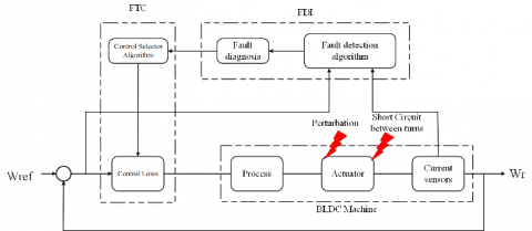
Figure 1. Block diagram for controlling the BLDC motor
Figure 1 shows the schematic diagram for controlling the BLDCM. For that, the following assumptions are made:
The simplified model of the BLDCM is shown in Figure 2:
Figure 2. The simplified model of the BLDCM
For a symmetrical winding and a balanced system, as shown in Figure 2, the vector of voltages across the three phases of the BLDC motor is given by:
$[\mathfrak{V}]=[\mathfrak{R}] \times[\mathfrak{I}]+[\mathfrak{L}] \times \frac{d[\mathcal{J}]}{d t}+[\mathfrak{E}]$ (1)
where,
$[\mathfrak{I}]=\left[\begin{array}{lll}
i_{a} & i_{b} & i_{c}
\end{array}\right]^{T}$ (2)
$[\mathfrak{E}]=\left[\begin{array}{lll}
e_{a} & e_{b} & e_{c}
\end{array}\right]^{T}$ (3)
$[\Re]=\left[\begin{array}{ccc}
R & 0 & 0 \\
0 & R & 0 \\
0 & 0 & R
\end{array}\right]$ (4)
$[\mathfrak{L}]=\left[\begin{array}{ccc}
L_{0} & M & M \\
M & L_{0} & M \\
M & M & L_{0}
\end{array}\right]$ (5)
$[\mathfrak{V}]=\left[\begin{array}{lll}
v_{a} & v_{b} & v_{c}
\end{array}\right]^{T}$ (6)
where, va, vb and vc are the phases voltages of the BLDCM, ia, ib and ic are the phases currents, R and $L=L_{0}-M$ are the resistance and inductance of the machine, ea, eb and ec are the electromotive forces of the phases.
The electric torque is given by:
$C_{c m}=\frac{[\mathfrak{I}] \times[\mathfrak{E}]^{T}}{\omega}$ (7)
where Ce is the electromagnetic torque and ωr is the angular velocity. So the model in Figure 1 can be written as follows:
$\left\{\begin{array}{l}
{[\mathfrak{V}]=[\Re] \times[\Im]+[\mathfrak{L}] \times \frac{d[\mathcal{J}]}{d t}+[\mathfrak{E}]} \\
C_{e m}=\frac{[\mathfrak{L}] \times[\mathfrak{E}]^{T}}{\omega} \\
\frac{d[\Omega]}{d t}=\frac{1}{J_{\text {inercie }}}\left(C_{\text {em }}-f_{\text {frotement }} \Omega-C_{\text {charge }}\right)
\end{array}\right.$ (8)
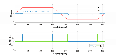
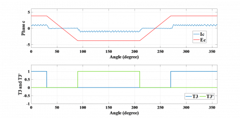
Depending on the position of the inductor, the current id is switched in phase at the time where the trapezoidal EMF has its flat part positive or negative, as shown in Figure 3.
(a) Current ia and FCEM ea and pulses T1 and T1
(b) Current ib and FCEM eb and pulses T2 and T2’
(c) Current ic and FCEM ec and pulses T3 and T3’
Figure 3. FTC managemnt for BLDC Machine
From the signals of the Hall sensors, the sequence is generated by choosing a sequence of notice pulses of transistors, which are well defined in Figure 3 where there are 6 distinct intervals noted IT. The opening of the 2 transistors of an arm of the electronic switch produces the conduction of a diode Dp and Dn.
3.1.1 Continuous model of BLDC motor
The main goal of developing a DC1 or DC2 continuous model of the BLDC motor is to validate a representation of the direct current at the input of the self-switched inverter for both modes when two phases are supplied DC1 or when three phases are supplied DC2.
The direct current id, derived from the direct current model and the three-phase model is practically similar.
DC1 Mode: DC1 mode corresponds to the two phases in series as represented in Figure 4.
Figure 4. Structure of the BLDC motor when two phases are supplied
This mode is then IT j intervals, we assume that the dynamic resistances of the components are identical:
$r_{\tau}=r_{D}=r$ (9)
In this case the voltage node checks:
$u_{d}=u_{1}-u_{2}$ (10)
where, u1 and u2 are respectively represent the voltage of the neutral point to the positive terminal and the voltage of the neutral point to the negative terminal of the continuous bus.
$\left\{\begin{array}{l}
u_{1}=V_{a}+v_{T}+r i_{a} \\
u_{2}=V_{b}-v_{T}+r i_{b}
\end{array}\right.$ (11)
By replacing va and vbby their respective expression (3) and (4), as ia= id and ib= -id; u1and u2 are givens by:
$\left\{\begin{array}{l}
u_{1}=R i_{d}+L_{c} \frac{d i_{d}}{d t}+e_{a}+v_{T}+r i_{d} \\
u_{2}=-R i_{d}+L_{c} \frac{d i_{d}}{d t}+e_{b}-v_{T}-r i_{d}
\end{array}\right.$ (12)
Therefore, udis given by:
$u_{d}=2(R+r) i_{d}+2 L_{c} \frac{d i_{d}}{d t}+\left(e_{a}-e_{b}\right)+2 v_{T}$ (13)
For the two phases in series, the FCEM present their party platform in opposition, so we have:
$-e_{b}=e_{a}=E=k_{e}\left|\omega_{r}\right|$ (14)
with ke the coefficient of the FCEM and ωr the rotation speed of the motor. Finally in this mode dynamics DC1 current id is expressed by:
$2 L_{c} \frac{d i_{d}}{d t}=u_{d}-2(R+r) i_{d}-2 E-2 v_{T}$ (15)
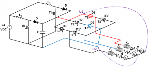
DC2 Mode: In this mode, a phase in series with the other two phases in parallel is presented in Figure 5:
Figure 5. Structure of the BLDC motor when three phases are supplied
In this case the voltages u1 and u2 are given by:
$u_{1}=V_{a}+v_{T}+r i_{a}$ (16)
And by replacing by the of expression va:
$u_{1}=(R+r) i_{a}+L_{c} \frac{d i_{a}}{d t}+e_{a}+v_{T}$ (17)
The paralleling of phase b and c leads to:
$\left\{\begin{array}{l}
u_{2}=V_{b}-v_{T}+r i_{b} \\
u_{2}=V_{c}+v_{D}+r i_{c}
\end{array}\right.$ (18)
And by replacing by the of expression vb and vc:
$\left\{\begin{array}{l}
u_{2}=(R+r) i_{b}+L_{c} \frac{d i_{b}}{d t}+e_{b}-v_{T} \\
u_{2}=(R+r) i_{c}+L_{c} \frac{d i_{c}}{d t}+e_{c}+v_{D}
\end{array}\right.$ (19.a, 19.b)
By adding (19.b) to (19.a), we get:
$2 u_{2}=(R+r)\left(i_{b}+i_{c}\right)+L_{c}\left(\frac{d i_{b}}{d t}+\frac{d i_{c}}{d t}\right)+e_{b}+e_{c}-v_{T}+v_{D}$ (20)
with $-\left(i_{b}+i_{c}\right)=i_{a}=i_{d}$, we have:
$\left\{\begin{array}{l}
u_{1}=(R+r) i_{a}+L_{c} \frac{d i_{a}}{d t}+e_{a}+v_{T} \\
2 u_{2}=-(R+r) i_{d}-L_{c} \frac{d i_{d}}{d t}+e_{b}+e_{c}+v_{D}-v_{T}
\end{array}\right.$ (21)
Consequently, the voltage ud satisfies the relation:
$u_{d}=u_{1}-u_{2}$ (22)
So,
$2 u_{d}=3(R+r) i_{d}+3 L_{c} \frac{d i_{d}}{d t}+2 e_{a}-e_{b}-e_{c}+3 v_{T}-v_{D}$ (23)
In addition, during this interval, we have significantly:
$e_{b}=-e_{a}=-E$ (24)
And,
$e_{c}=e_{a}=E$ (25)
Finally, the dynamic of the current id check in DC2 mode is given by:
$3 L_{c} \frac{d i_{d}}{d t}=2 u_{d}-3(R+r) i_{d}-2 E-3 v_{T}+v_{D}$ (26)
3.2 Modeling with fault
The model simplified of the BLDCM with a fault is shown in Figure 6:
Figure 6. The model simplified of the BLDCM with fault
The vector of voltages across the three phases of the BLDC motor is given by:
$[\mathfrak{V}]=[\Re] \times[\mathfrak{I}]+[\mathfrak{L}] \times \frac{d[\mathcal{J}]}{d t}+[\mathfrak{E}]$ (27)
where the phases Voltages are:
$[\mathfrak{V}]=\left[\begin{array}{lll}
v_{a} & v_{b} & v_{c}
\end{array}\right]^{T}$ (28)
The phases currents are:
$[\mathfrak{I}]=\left[\begin{array}{llll}
i_{a} & i_{b} & i_{c} & i_{c c}
\end{array}\right]^{T}$ (29)
with the electromotive forces of the phases:
$[\mathfrak{E}]=\left[\begin{array}{llll}
c_{a} & c_{b} & c_{c} & c_{c c}
\end{array}\right]^{T}$ (30)
And the resistance and inductance of the motor are:
$[\Re]=\left[\begin{array}{cccc}
R & 0 & 0 & -R^{\prime \prime} \\
0 & R & 0 & 0 \\
0 & 0 & R & 0 \\
-R^{\prime \prime} & 0 & 0 & \left(R^{\prime \prime}+R_{c c}\right)
\end{array}\right]$ (31)
$[\mathfrak{L}]=\left[\begin{array}{cccc}
L & 0 & 0 & -L^{\prime \prime} \\
0 & L & 0 & M_{f} \\
0 & 0 & L & M_{f} \\
-L^{\prime \prime} & M_{f} & M_{f} & L^{\prime \prime}-M^{\prime \prime}
\end{array}\right]$ (32)
where, va, vb and vcare the phases voltages of the BLDCM, ia, ib and icare the phases currents, icc is the current of short circuit, R and L are the resistance and inductance of the motor, Rcc is the resistance of shunt of short circuit, R” is the resistance of turns short circuited, M” is the inductance mutual between the turns short circuited and the coil of phase a, Mf is the inductance mutual between the turns short circuited and the coil of phase b and c, ea; eband ecare the electromotive forces of the phases and ecc is the electromotive forces of the turns short circuited.
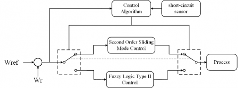
In order to keep the robustness of the control by fuzzy logic type 2 and to avoid the high level of energy consumed by the micro-controllers, without deteriorating the performance of the system, we propose a new “hybrid” control scheme to be applied robustly to the BLDC motor Figure 7.
This involves using an algorithm allowing switching between two control laws: the first by sliding mode which acts essentially during the breast regime, and the second by type 2 fuzzy logic active when a short-circuit fault deteriorates the system performance. The Figure 8 shows the structure of this algorithm.
4.1 Super-Twisting algorithm
This algorithm was developed for the control of systems with a relative degree equal to 1 with respect to the sliding surface. It was studied by Levant [46]. It is made up of a discontinuous part U2 and a continuous part U1 such that:
Figure 7. Schematic diagram of the Active Fault-Tolerant Control of Brushless DC Motor
Figure 8. Structure of the control algorithm
$U_{d}=U_{1}+U_{2}$ (33)
And,
$U_{2}=\left\{\begin{array}{ll}
-\lambda\left|S_{0}\right|^{\rho} \operatorname{sign}(S), & |S| \succ S_{0} \\
-\lambda|S|^{\rho} \operatorname{sign}(S), & |S| \leq S_{0}
\end{array}\right.$ (34)
$\dot{U}_{1}=\left\{\begin{array}{ll}
-U, & |U| \succ 1 \\
-\alpha \operatorname{sign}(S), & |U| \leq 1
\end{array}\right.$ (35)
$\left\{\begin{array}{l}
\dot{\omega}=\frac{1}{j}\left(-f . \omega-C r+k_{v} \cdot I_{d}\right) \\
\dot{I}_{d}=\frac{1}{L^{\prime}}\left(2 v_{t}-E-R^{\prime} . I_{d}+U_{d}\right)
\end{array}\right.$ (36)
$y=\omega$ (37)
So,
$\dot{y}=\dot{\omega}$ (38)
$\dot{y}=\frac{1}{j}\left(-f . \omega-C r+k_{v} \cdot I_{d}\right)$ (39)
So we have:
$\ddot{y}=\frac{1}{j}\left(-f \cdot \dot{\omega}-C r+\frac{k_{v}}{L^{\prime}}\left(2 v_{t}-E-R^{\prime} . I_{d}+U_{d}\right)\right)$ (40)
We derived the output twice for the command appeared. So, the relative degree of this surface compared to the control input is equal to two.
By taking:
$S=e=\omega-\omega_{r e f}$ (41)
With,
$\begin{aligned}
S^{(2)}=\ddot{e}=\frac{1}{j}(-f& . \dot{\omega}-C r \\
&\left.+\frac{k_{v}}{L^{\prime}}\left(2 v_{t}-E-R^{\prime} . I_{d}+U_{d}\right)\right) \\
&-\ddot{\omega}_{r e f}
\end{aligned}$ (42)
$\begin{array}{r}
S^{(2)}=\frac{1}{j}\left(-f . \dot{\omega}-C r+\frac{k_{v}}{L^{\prime}}\left(2 v_{t}-E-R^{\prime} \cdot I_{d}\right)\right. \\
\left.-j \ddot{\omega}_{r e f}\right)+\frac{k_{v}}{j L^{\prime}} U_{d}
\end{array}$ (43)
This equation can be put in the following form:
$\varphi(x, t)=\frac{1}{j}\left(-f . \dot{\omega}-C r+\frac{k_{v}}{L^{\prime}}\left(2 v_{t}-E-R^{\prime} . I_{d}\right)-j \ddot{\omega}_{r e f}\right)$ (44)
And,
$\phi(x, t)=\frac{k_{v}}{j L^{\prime}} U_{d}$ (45)
So the super twisting algorithm can be applied.
By considering C0 = 0.3227, km= 13.7367, and kM= 13.7369,
$-C_{0} \prec \varphi(x, t) \prec C_{0} \text { and } 0 \prec K_{m} \leq \phi(x, t) \leq K_{M}$
Then we will fix α = 0:7422; λ = 650:3383; and ρ = 0:01, such as:
$\alpha \prec \frac{C_{0}}{K_{m}}, \lambda^{2} \geq \frac{4 C_{0} \cdot K_{M}\left(\alpha+C_{0}\right)}{K_{m}^{3}\left(\alpha-C_{0}\right)} \text { et } 0 \prec \rho \prec 0.5$
We accept that $|S| \leq S_{0} \text { et }|U| \leq 1$ So the control low written as follows:
$U_{d}=-\lambda|S|^{\rho} \operatorname{sign}(S)+U_{1}$ (46)
With,
$\dot{U}_{1}=-\alpha \cdot \operatorname{sign}(S)$ (47)
4.2 Control using the interval type-2 T-S fuzzy logic
4.2.1 Type-2 fuzzy logic control context
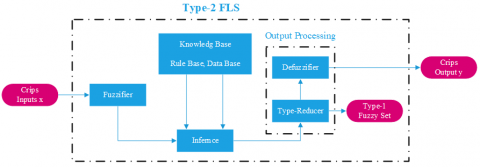
Classic fuzzy logic (Type-1) has been generalized to a new type of fuzzy logic called fuzzy logic-2. In recent years, a theoretical basis for this new logic has been built by Mendel and his colleagues who have indeed demonstrated its effectiveness and superiority over fuzzy type 1 logic [47, 48]. The fuzzy set of type 2 is characterized by a fuzzy membership function, such that the membership value (degree of membership) of each element of the set is a fuzzy set in [0, 1]. Such sets can be used in situations where we have uncertainty about the membership values themselves. Uncertainty can take the form of the membership function or one of its parameters [49]. The structure of a type 2 fuzzy system is shown in Figure 9:
Figure 9. IT2FLC structure block diagram
The differences between the Interval type 2 Fuzzy logic control set and Interval type 2 Fuzzy logic control set are explained in two fundamental differences [50]:
First difference is Adaptiveness, meaning that the embedded T1 FSs used to compute the bounds of the type-reduced interval change as input changes.
And the second one is Novelty, meaning that the UMF and LMF of the same IT2 FS may be used simultaneously in computing each bound of the type-reduced interval. As a result, an IT2 FLC can implement a complex control surface that cannot be achieved by a T1 FLC using the same rule base.
4.2.2 Active FTC design
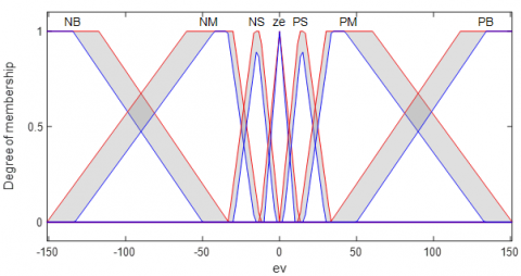
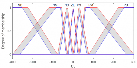
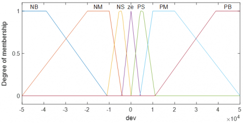
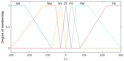
The used labels of the fuzzy variable residue and its derivative are: Negative Big (NB), Negative Medium (NM), Negative Small (NS), Zero (ZE), Positive Small (PS), Positive Medium (PM) and Positive Big (PB). We chose a trapezoidal membership functions for six fuzzy input variable which are NB, NM, NS, PS, PM and PB and we choose a triangular membership functions for the fuzzy input variable ZE for all upper and lower membership functions. The corrective control is decomposed into seven levels, so the total rules can be 49 as presented in Table 1.
u(k) = ufs + upi (48)
Table 1. Fuzzy rules
|
ev |
Dev |
||||||
|
NB |
NM |
NS |
ZE |
PS |
PM |
PB |
|
|
NB |
NB |
NB |
NB |
NB |
NM |
NS |
ZE |
|
NM |
NB |
NB |
NB |
NM |
NS |
ZE |
PS |
|
NS |
NB |
NB |
NM |
NS |
ZE |
PS |
PM |
|
ZE |
NB |
NM |
NS |
ZE |
PS |
PM |
PB |
|
PS |
NM |
NS |
ZE |
PS |
PM |
PB |
PB |
|
PM |
NS |
ZE |
PS |
PM |
PB |
PB |
PB |
|
PB |
ZE |
PS |
PM |
PB |
PB |
PB |
PB |
Figure 10. IT2FLC INPUT EV
Figure 11. IT2FLC INPUT DEV
Figure 12. IT2FLC OUTPUT Uc
Figure 10, Figure 11 and Figure 12 present the type-2 membership functions for the IT2FLC.
And the Figure 13, Figure 14 and Figure 15 present the type-1 membership functions for the IT1FLC.
Figure 13. IT1FLC INPUT EV
Figure 14. IT1FLC INPUT DEV
Figure 15. IT1FLC OUTPUT Uc
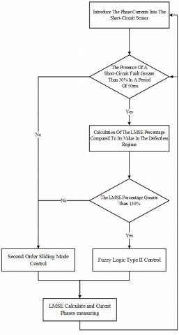
4.3 Detection method
The principle of our hybrid FTC control type between the second Order Sliding Mode order and the fuzzy logic type 2 is to choose a control between these two commands by an algorithm occurs according to an expertise made in relation to the consequences of a short-circuit fault between turns. This algorithm consists of three steps, namely:
- The first step: its role is the detection of the existence of a short-circuit defect which gives us a percentage of the existence of a defect over a given period equal to 50 ms.
- The second step: its role and just to give a percentage of the value of Least Mean Square Error (LMSE) versus a value of LMSE in a breast regime in each 10ms.
- The third step: it can be called a decision part that decide which command intervenes. It requires the results of the other two algorithms.
4.3.1 Fault tolerant control management for BLDC Machine
The flowchart in Figure 16 summarizes the principle of this control technique.
Figure 16. FTC management for BLDC motor
In this section, simulations results are presented to illustrate the performance and the robustness of the proposed control law when applied to the BLDC Motor. The parameters values of the motor are shown in Table 2.
Table 2. BLDC motor parameters
|
Parameter |
Symbol |
Value |
|
Resistance of phase |
R |
4 Ω |
|
Phase inductance |
Lc |
0.002 H |
|
Inertia constant |
J |
4.65e-6 kg.m2 |
|
Back-EMF Constant |
Ke |
26.1e-3 V/rd.s-1 |
|
Coefficient of friction |
Kf |
1.5e-006 N.m/rd.s-1 |
|
Supply voltage |
Un |
48 (V) |
|
Rated current |
In |
2 (A) |
Figure 17 shows the chronogram of the application of the changes on the load torque and the application of a short circuit fault between turns on the BLDC motor where:
Figure 17. Faults Chronogram withe fault detection signal
Figure 18 shows the control that occurs during the existence or the absence of a short- circuit defect with the percentage of LMSE in each 10 ms period where:
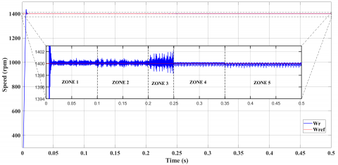
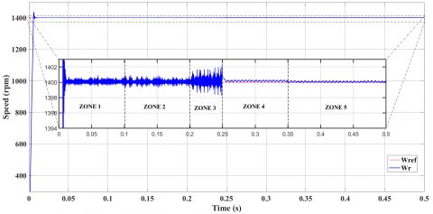
Figure 19 represents the speed response.
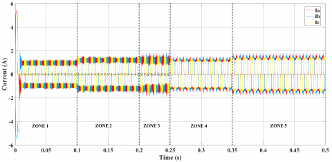
Figure 20 presents the three phases’ currents in the 5 different zones.
Figure 18. Control signal with the fault detection signal for the control
Figure 19. The speed response for the control with IT2FLC
Figure 20. Three phases’ currents Iabc for the control with IT2FLC
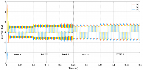
Figure 21. The speed response for the control with IT1FLC
Figure 22. Three phases’ currents Iabc for the control with IT1FLC
Figure 21 and Figure 22 present the speed response and the three phases currents for the control with IT1FLC to sohwing the differnce in performonc between the IT1FLC and IT2FLC.
Table 3. Values of the performance criteria of the proposed FTC withe IT2FLC and the control withe IT1FLC in the faulty mode
|
|
ISE |
IAE |
ITSE |
ITAE |
|
|
$\int_{0}^{T} e^{2}(t)$ |
$\int_{0}^{T}|e(t)|$ |
$\int_{0}^{T} t e^{2}(t)$ |
$\int_{0}^{T} \boldsymbol{t}|\boldsymbol{e}(\boldsymbol{t})|$ |
|
Interval Type-2 Fuzzy logic |
0.0027 |
0.0132 |
8.1540e-04 |
0.0039 |
|
Interval Type-1 Fuzzy logic |
0.1596 |
0.1260 |
0.0481 |
0.0379 |
In the faulty mode, four most known performance criteria are used to make a quantitative comparison between the proposed Interval Type-2 Fuzzy logic and Interval Type-1 Fuzzy Logic. These are integral of square error (ISE), integral of the absolute value of the error (IAE), integral of the time multiplied by the square value of the error (ITSE), and integral of the time multiplied by the absolute value of the error (ITAE). The obtained values for each criterion are summarized in Table 3.
After the robustness test, the speed with the second order sliding mode control remains practically insensitive to the disturbance of the load torque.
After the presence of a short-circuit fault, it has been found that the switch between the commands occurs after 50 ms the time of the fault detection in this period the command by second order sliding mode does not give us the right results.
After the fault detection of short-circuit, algorithm switches the command from the second order sliding Mode to fuzzy logic type 2.
There is a marked improvement in the results of the control by fuzzy logic type 2 compared to the control by second order sliding mode in the presence of a defect.
After the second robustness test, the speed with the fuzzy logic type 2 is still insensitive to a large increase in load torque.
BLDC Motor Speed Control Tests show that Hybrid Control Second Order Sliding Mode – fuzzy logic type 2 provides good performance even in the presence of an external defect.
This paper presents a new method of fault tolerant control based on hybrid control between the Type-II fuzzy logic control and the second order sliding mod control for a BLDC motor with short circuit fault between turns and parameter variations. This motor demands fault tolerant performance in the industrial sector, to achieve our goal a continuous mathematical model of BLDC motor was presented. Based on this model, we synthesized two control strategies for BLDC based on type-2 fuzzy logic and second order sliding modes. we use an algorithm for the phase current imbalances and the short circuit between turns faults detection, this algorithm plays the role of an observer to eliminate this fault, the two control methods, which have verified the sufficient condition of stability according to Lyapunov's theory, are designed to improve the static and dynamic performance of the BLDC in the event of the occurrence of the fault. The obtained simulation results illustrate the good performance of the proposed method in the case of the fault when we compared with the hybridization of this technique with the type 1 fuzzy logic. This work allowed us to conclude that the hybridization control between the artificial intelligence techniques can tolerate some important faults such as: short circuit fault between turns and parameter variations.
[1] Yadav, N., Yadav, A., Bansal, J.C., Deep, K., Kim, J.H. (2018). Harmony Search and Nature Inspired Optimization Algorithms: Theory and Applications, ICHSA 2018. https://doi.org/10.1007/978-981-13-0761-4
[2] Xia, C.L. (2012). Permanent Magnet Brushless DC Motor Drives and Controls. John Wiley & Sons. https://doi.org/10.1002/9781118188347.ch3
[3] Piotr, W. (2011). Dynamics and control of electrical drives. Springer Science & Business Media. ISBN: 978-3-642-20221-6
[4] Kim, S.H. (2017). Electric Motor Control: DC, AC, and BLDC Motors. Elsevier.
[5] Hu, H., Wang, T., Zhao, S., Wang, C. (2019). Speed control of brushless direct current motor using a genetic algorithm–optimized fuzzy proportional integral differential controller. Advances in Mechanical Engineering, 11(11). https://doi.org/10.1177/1687814019890199
[6] Cao, J.B., Cao, B.G. (2009). Fuzzy-logic-based sliding-mode controller design for position-sensorless electric vehicle. IEEE Transactions on Power Electronics, 24(10): 2368-2378. https://doi.org/10.1109/TPEL.2009.2020429
[7] Bagavathy, S., Maruthupandi, P. (2019). Sensorless cluster based neural-fuzzy control strategy for four quadrant operation of three phase BLDC motor with load variations. Cluster Computing, 22(3): 6855-6864. https://doi.org/10.1007/s10586-017-1639-0
[8] Mo, L., Liu, Y., Zhang, Y. (2019). Sliding mode variable structure control for surface permanent magnet synchronous motors based on a fuzzy exponential reaching law. Mathematical Problems in Engineering. https://doi.org/10.1155/2019/8340956
[9] Singh, A.K., Chhabra, A., Chhillar, A., Ranga, A., Dahiya, R. (2017). Fuzzy logic based controllers for speed control of BLDC motor. Int. J. Res. Appl. Sci. Eng. Technol, 5(6): 985-1001.
[10] Kwong, W.A., Passino, K.M., Laukonen, E.G., Yurkovich, S. (1995). Expert supervision of fuzzy learning systems for fault tolerant aircraft control. Proceedings of the IEEE, 83(3): 466-483. https://doi.org/10.1109/5.364491
[11] Eryurek, E., Upadhyaya, B.R. (1995). An integrated fault tolerant control and diagnostics system for nuclear power plants. In Proceedings of the Topical Meeting on Computer Based Human Support Systems: Technology, Methods and Future, pp. 267-274.
[12] Aubrun, C., Sauter, D., Noura, H., Robert, M. (1993). Fault diagnosis and reconfiguration of systems using fuzzy logic: application to a thermal plant. International Journal of Systems Science, 24(10): 1945-1954. https://doi.org/10.1080/00207729308949606
[13] Mhaskar, P., Liu, J., Christofides, P.D. (2012). Fault-tolerant process control: methods and applications. Springer Science & Business Media.
[14] Zhang, Y., Jiang, J. (2008). Bibliographical review on reconfigurable fault-tolerant control systems. Annual Reviews in Control, 32(2): 229-252. https://doi.org/10.1016/j.arcontrol.2008.03.008
[15] Mekki, H., Benzineb, O., Boukhetala, D., Tadjine, M., Benbouzid, M. (2015). Sliding mode based fault detection, reconstruction and fault tolerant control scheme for motor systems. ISA Transactions, 57: 340-351. https://doi.org/10.1016/j.isatra.2015.02.004
[16] Aghili, F. (2010). Fault-tolerant torque control of BLDC motors. IEEE Transactions on Power Electronics, 26(2): 355-363. https://doi.org/10.1109/TPEL.2010.2060361
[17] Papathanasopoulos, D.A., Mitronikas, E.D. (2018). Fault tolerant control of a brushless dc motor with defective position sensors. In 2018 XIII International Conference on Electrical Machines (ICEM), pp. 1503-1509. https://doi.org/10.1109/ICELMACH.2018.8507013
[18] Neethu, S., Sreelekha, V. (1970). Open phase fault tolerant control of BLDC Motors. International Journal of Advanced Research in Electrical, Electronics and Instrumentation Engineering, 2(1): 176-181.
[19] Moon, J.J., Lee, W., Park, S.W., Kim, J. M. (2015). Fault tolerant control method of seven-phase BLDC motor in asymmetric fault condition due to open phase. In 2015 9th International Conference on Power Electronics and ECCE Asia (ICPE-ECCE Asia), pp. 1591-1596. https://doi.org/10.1109/ICPE.2015.7167989
[20] Shakouhi, M., Mohamadian, M., Afjei, E. (2014). Fault-tolerant control of brushless DC motors under static rotor eccentricity. IEEE Transactions on Industrial Electronics, 62(3): 1400-1409. https://doi.org/10.1109/TIE.2014.2365439
[21] Mousmi, A., Abbou, A., El Houm, Y. (2019). Real-time implementation of a novel hybrid fuzzy sliding mode control of a BLDC motor. International Journal of Power Electronics and Drive Systems, 10(3): 1167-1177. https://doi.org/10.11591/ijpeds.v10.i3.pp1167-1177
[22] Al Mashhadany, Y.I. (2014). Adaptive speed control system based on interval type-2 fuzzy logic. Transactions on Machine Learning and Artificial Intelligence, 2(5): 27-40. https://doi.org/10.14738/tmlai.25.500
[23] Loukal, K., Benalia, L. (2016). Interval type-2 fuzzy gain-adaptive controller of a doubly fed induction machine (DFIM). Journal of Fundamental and Applied Sciences, 8(2): 470-493. https://doi.org/10.4314/jfas.v8i2.20
[24] Ramya, A., Ahamed, I., Balaji, M. (2016). Hibridni samopodešavajući fuzzy PID regulator za upravljanje brzinom bezkolektorskog istosmjernog motora. Automatika: časopis za automatiku, mjerenje, elektroniku, računarstvo i komunikacije, 57(3): 672-679. https://doi.org/10.7305/automatika.2017.02.1769
[25] Mohd Zaihidee, F., Mekhilef, S., Mubin, M. (2019). Robust speed control of PMSM using sliding mode control (SMC)-A review. Energies, 12(9): 1669. https://doi.org/10.3390/en12091669
[26] Monteiro, J.R.B.A., Oliveira, C.M.R., Aguiar, M.L. (2015). Sliding mode control of brushless DC motor speed with chattering reduction. In 2015 IEEE 24th International Symposium on Industrial Electronics (ISIE), pp. 542-547. https://doi.org/10.1109/ISIE.2015.7281525
[27] Kommuri, S.K., Lee, S.B., Veluvolu, K.C. (2017). Robust sensors-fault-tolerance with sliding mode estimation and control for PMSM drives. IEEE/ASME Transactions on Mechatronics, 23(1): 17-28. https://doi.org/10.1109/TMECH.2017.2783888
[28] Zhang, H., Tu, Y., Wang, T. (2014). Sensor-less control for brushless DC motors based on hybrid sliding mode observer. In 2014 7th International Conference on Intelligent Computation Technology and Automation, pp. 636-639. https://doi.org/10.1109/ICICTA.2014.158
[29] Zhang, Q.C., Ma, R.Q., Deng, J.J., Zhao, B. (2015). A cascade first and second order sliding mode control approach for speed control of brushless DC motor. In 2015 34th Chinese Control Conference (CCC), pp. 3319-3326. https://doi.org/10.1109/ChiCC.2015.7260151
[30] Munoz-Gomez, G., Alanis, A.Y., Rivera, J. (2018). Nested high order sliding mode controller applied to a brushless direct current motor. IFAC-PapersOnLine, 51(13): 174-179. https://doi.org/10.1016/j.ifacol.2018.07.274
[31] Damiano, A., Gatto, G., Pisano, A., Usai, E. (1999). Digital second order sliding mode control of PM DC motor. In ISIE'99 Proceedings of the IEEE International Symposium on Industrial Electronics (Cat. No. 99TH8465), 1: 322-326. https://doi.org/10.1109/ISIE.1999.801806
[32] Merabet, A. (2019). Cascade second order sliding mode control for permanent magnet synchronous motor drive. Electronics, 8(12): 1508. https://doi.org/10.3390/electronics8121508
[33] Lavanya, M., Brisilla, R.M., Sankaranarayanan, V. (2012). Higher order sliding mode control of permanent magnet DC motor. In 2012 12th International Workshop on Variable Structure Systems, pp. 226-230. https://doi.org/10.1109/VSS.2012.6163506
[34] Fauroux, J.C., Sanchez, C., Sartor, M. (1998). Application d'une methode de classement par la logique floue à la conception preliminaire de mecanismes application of a fuzzy logic ordering method to preliminary mechanism design.
[35] Abdelghafour, H., Abderrahmen, B., Samir, Z., Riyadh, R. (2019). Hybrid type-2 fuzzy sliding mode control of a doubly-fed induction machine (DFIM). Advances in Modelling and Analysis C, 74(2-4): 37-46. https://doi.org/10.18280/ama_c.742-401
[36] Zeghlache, S., Mekki, H., Bouguerra, A., Djerioui, A. (2018). Actuator fault tolerant control using adaptive RBFNN fuzzy sliding mode controller for coaxial octorotor UAV. ISA Transactions, 80: 267-278. https://doi.org/10.1016/j.isatra.2018.06.003
[37] Barghandan, S., Badamchizadeh, M.A., Jahed-Motlagh, M.R. (2017). Improved adaptive fuzzy sliding mode controller for robust fault tolerant of a quadrotor. International Journal of Control, Automation and Systems, 15(1): 427-441. https://doi.org/10.1007/s12555-015-0313-7
[38] Zeghlache, S., Ghellab, M.Z., Bouguerra, A. (2017). Adaptive type-2 fuzzy sliding mode control using supervisory type-2 fuzzy control for 6 DOF octorotor aircraft. International Journal of Intelligent Engineering and Systems, 10(3): 47-57. https://doi.org/10.22266/ijies2017.0630.06
[39] Zeghlache, S., Djerioui, A., Benyettou, L., Benslimane, T., Mekki, H., Bouguerra, A. (2019). Fault tolerant control for modified quadrotor via adaptive type-2 fuzzy backstepping subject to actuator faults. ISA transactions, 95: 330-345. https://doi.org/10.1016/j.isatra.2019.04.034
[40] Li, T., Zhang, Y., Gordon, B.W. (2012). Nonlinear fault-tolerant control of a quadrotor UAV based on sliding mode control technique. IFAC Proceedings Volumes, 45(20): 1317-1322. https://doi.org/10.3182/20120829-3-MX-2028.00056
[41] Keltoum, L., Leila, B., Abderrahmen, B. (2017). Speed control of a doubly-fed induction motor (DFIM) based on fuzzy sliding mode controller. International Journal of Intelligent Engineering and Systems, 10(3): 20-29. https://doi.org/10.22266/ijies2017.0630.03
[42] Abdelghafour, H., Abderrahmen, B., Samir, Z., Riyadh, R. (2018). Backstepping control of a doubly-fed induction machine based on fuzzy controller. European Journal of Electrical Engineering, 20(5-6): 645. https://doi.org/10.3166/ejee.20.645-657
[43] Boukhalfa, G., Belkacem, S., Chikhi, A., Benaggoune, S. (2018). Direct torque control of dual star induction motor using a fuzzy-PSO hybrid approach. Appl. Comput. https://doi.org/10.1016/j.aci.2018.09.001
[44] Layadi, N., Zeghlache, S., Djerioui, A., Mekki, H., Houari, A., Benkhoris, M.F., Berrabah, F. (2018). Interval type-2 fuzzy adaptive strategy for fault tolerant control based on new faulty model design: Application to DSIM under broken rotor bars fault. AMSE Journals, Modelling, Measurement and Control A, 91(4): 212-221. https://doi.org/10.18280/mmc_a.910407
[45] Laggoun, L., Kiyyour, B., Boukhalfa, G., Belkacem, S., Benaggoune, S. (2019). Direct torque control using fuzzy second order sliding mode speed regulator of double star permanent magnet synchronous machine. In International Conference on Electrical Engineering and Control Applications, pp. 139-153. https://doi.org/10.1007/978-981-15-6403-1_10
[46] Levant, A. (1993). Sliding order and sliding accuracy in sliding mode control. International Journal of Control, 58(6): 1247-1263. https://doi.org/10.1080/00207179308923053
[47] Sudha, K.R., Santhi, R.V. (2011). Robust decentralized load frequency control of interconnected power system with generation rate constraint using type-2 fuzzy approach. International Journal of Electrical Power & Energy Systems, 33(3): 699-707. https://doi.org/10.1016/j.ijepes.2010.12.027
[48] Lam, H.K., Seneviratne, L.D. (2008). Stability analysis of interval type-2 fuzzy-model-based control systems. IEEE Transactions on Systems, Man, and Cybernetics, Part B (Cybernetics), 38(3): 617-628. https://doi.org/10.1109/TSMCB.2008.915530
[49] Patel, H.R., Shah, V.A. (2018). A framework for fault-tolerant control for an interacting and non-interacting level control system using ai. In ICINCO, (1): 190-200.
[50] Wu, D. (2013). Two differences between interval type-2 and type-1 fuzzy logic controllers: Adaptiveness and novelty. In Advances in Type-2 Fuzzy Sets and Systems, pp. 33-48. https://doi.org/10.1007/978-1-4614-6666-6_3