Lim Wei Jie | Teoh Poh Sen | Nor Maniha Abdul Ghani* | Mohammad Fadhil Abas
© 2021 IIETA. This article is published by IIETA and is licensed under the CC BY 4.0 license (http://creativecommons.org/licenses/by/4.0/).
OPEN ACCESS
This work focuses on the implementation and design of a six degree of freedom, 6-DOF control of automatic color sorting and pick and place tasks for a robot arm using wireless controlling interface – Blynk apps. Based on the collaboration between the servo motor and input color sensor, this wireless control of automatic color sorting robot arm provides a powerful wireless control GUI (Graphics User Interface) and to enable the method for manual color sorting mode. The color sorting mode is performed once the mode is turned on by the user. The robot arm able to differentiate the colors of the object (input) and categorize or classify the object to the correct places automatically. It provides a stable, efficient, and precision results without any vibration of control as the main target for this project. In this work, six servo motors were used to realize the real robotic arm for industrial use. Five servos were operated to control the entire robot arm motion including the base, shoulder, and elbow as well as one servo is reserved for the positioning of the end effector. Two input variables namely TSC3200 Color Sensors & HC-SR04 Ultrasonic Sensors were employed as the input for the robot arm. The output variable mainly focused on the servo motor as the links for the robot arm to reposition and change the motion for the entire system.
automatic wireless control, color sorting, 6-DOF robot arm, IOT-Blynks apps, pick and place tasks
Robotic manipulators that can replace and perform tasks similar to the human arm are known as robotic arms. A typical industrial robot arm includes a series of joints, articulations, and manipulators that function together to closely resemble the motion either in linear displacement or rotational displacement and it has the functionality of a human arm. A robot arm is usually programmable to achieve all the functions and tasks that are needed by the user with the combination of the mechanical structure of the robot’s link coupled with the translating joint or rotational joints. This project consisted of 6 Degree of Freedom Robot Arm that allows considerable freedom movement for the end-user full control purpose.
Automation denotes the level in which the equipment can operate automatically, towards or beyond mechanization, instead of using physical labor to perform or operate the functions manually. An automation system is integrated with the use of a feedback control loop, automatic actuating drivers as well as the sensory systems. The automation system provides higher productivity and produces quality products, improve the safety and reliability of the products, reduce the need for periodic checking as well as reduce the cost of production. Industrial automation, specifically industrial robot control solution, is the main focus of this project. This type of automated machine (Color Sorting Robot Arm) is able to perform repeatable tasks for a longer duration according to the desired speed.
The arms of the color sorting robot arms are developed to perform in manufacturing industries for various fields such as the bottle filling industry, packing industry, and surveillance industry for example in detecting and destroying bombs. Uzma et al. fabricated a robot arm with a color sorting function using the TCS3200 color sensor that aims to design an efficient system to help distinguish the colors of objects and put them to the correct position when it detects a wrong color and does nothing when the color is correct. The objectives of the project are to optimize productivity, decrease the cost of products, and decrease human mistakes in the industrial applications of the robot [1].
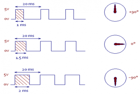
The robot arm is implemented with 2 degrees of freedom with an RF controller. The RF control module for controlling the robot system will be discussed in this work. One of the earlier works that used this approach was the robot arm control with Arduino [2]. A 4 axes robot arm with 5 Micro Servo Motors was assembled in this study. This paper discussed the coordinate frames and transformation of matrices involving all the joints and links to determine the degree of freedom of the general robot arm. Another work that used this approach was the Human Controlled Robotic Arm [3]. The output of this paper involved designing a robot arm using a PID controller with a closed-loop feedback system. This project used human hand motion as the input for the robot arm movement, including grasping and rotating the arm of the robot arm. In 2014, Faravar [4] published a paper in which they described a Robotic Arm Using PIC 16F877A Microcontroller. This paper focused on the servo motor pulse width derivation and all related information about the pulse and signal of the Servo Motors.
In 2015, Muhammed et al. [5] demonstrated the Wireless Control of Pick and Place Robotic Arm Using an Android Application. This paper dealt with the wireless interaction using the Bluetooth module and Android-based graphics user interface (GUI) for the robot arm motion control. The command is transmitted via Bluetooth communication to control the movement of the robot arm DC motors and announced the touchscreen-based interface operation in 2015. Another project that used this approach for controlling the robot arm wirelessly was in the research conducted by Behera [6]. The author used the XBee wireless module for remotely controlling the robotic arm using a graphic user interface on the PC. A Sony PlayStation remote controller was utilized in this project as the main controller for the robotic arm pick and place task. The XBee wireless module, which contained an antenna and AT command sets, was made available for the module. Previous research had shown that the robot arm used the RFID wireless communication protocol for controlling and providing command and interaction between the robot arm and the microcontroller [7]. The chip module used was the NRF24L01, a transceiver module which provided a full duplex to transmit and receive the data simultaneously. This wireless module was able to provide a transfer rate of up to 2 Mbps and a frequency of 2.4 Ghz.
The first stage of the color sorting task required an input component that was any related light reflection sensor that was able to transfer the light scaling into the data. This enabled it to be read by the computer or microcontroller. Reddy et al. [8] carried out a numerical study of sorting of objects based on colour by pick and place robotic arm using the IR object vision sensors to sense the color of objects and the robotic arm will grasp and place the object according to different colors. The approach used in this study was limited to color detection. The color was either black or white. The limitation was due to the infrared sensors used, which was only able to transmit the black and white signal to the microcontroller. Recently, a TSC230 color sensor project performed by Thike et al. [9] was a more advanced and accurate color sensor robot arm that was able to sort Red, Green, and Blue (RGB) color. With the combined task of the output component (Servo Motors – actuator for robot arm) and input component (TCS320 Color Sensor), the whole robot system offered a complete and satisfactory operation of color sorting to provide an accurate sorting function. In comparison to the previous works in color sorting function [10-16], this research offered a variety of color signals that can be read by the sensor and transferred to the microcontroller. Nevertheless, the lack of automatic and wireless functions posed some limitations and thus will be the main focus of this work. In order to solve this, Arduino UNO (with coding) and WIFI module is used to overcome lack of automatic and wireless functions. Therefore, an integration between the IOT-Blynk GUI and the 6 DOF Robot arm will be developed for servo positioning to perform color sorting function in manual and wireless auto-mode.
The rest of the article is structured as follows: Section 2 illustrates the system development and design. The Result and analysis are described in Section 3 and Section 4 provides the conclusion.
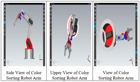
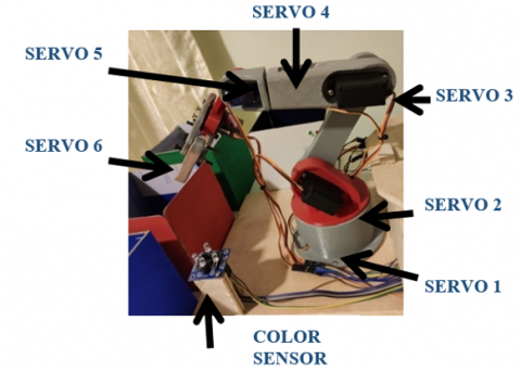
In this research, six servo motors were used to move the robot arm because it is highly sensitive and accurate for every position desired. Color sensor TCS3200 was used to perform the color sorting function, Ultrasonic ranging module HC-SR04 was used for assembling, in the project, for distance ranging, and as a detector for the presence of objects. The ESP-01 WiFi Serial Transceiver Module is the main communication medium for any device that needs to connect to Arduino for purpose of reading the data. The main core of the entire project is Arduino Uno, the microcontroller open-source electronics prototyping platform. The ATMEGA328P, as the core microcontroller for the board, provides high performance and low power consumption features [17-22]. For the mechanical function, the robot arms are constructed in solid works as shown in Figure 1, and the robot arm hardware development is supported by six servo motors is shown in Figure 2.
Figure 1. Robot arm drawing in 3D solid work
Figure 2. Hardware development of color sorting robot arm
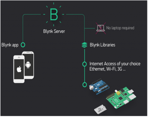
The main IoT system for this project is based on a ready free of charge IoT Graphic User Interface – Blynk app, which can be found in the Google Play Store application market in the Android platform of App Store for the IOS platform. Blynk library and server provide a powerful and stable IoT system for open source used as well as freely available for modifying and developing using the source code. The Blynk Interface provides various buttons and sliders which are able to be freely used by users. The Blynk interface provides a strong interaction between Arduino and a lot of hardware in the market. Hence, Blynk is used for this project as the main controlling UI for the color sorting robot arm. The planning of the interface design is as follows:
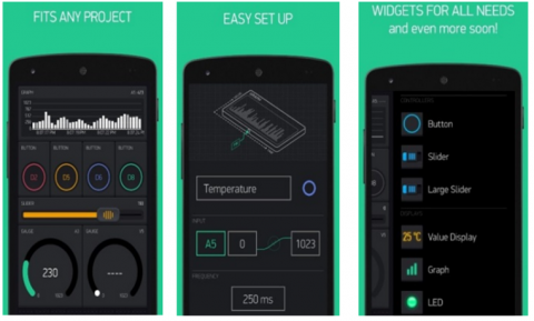
Figure 3 shows the IoT interaction of Blynk Interface while Figure 4 shows the features of the Blynk Interface. Figure 5 shows the initial process of the flowchart for the color sorting robot arm.
Figure 3. IoT interaction of Blynk Interface
Figure 4. Features of the Blynk Interface
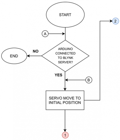
Figure 5. Initial process flowchart
The starting of the project will mainly focus on the communication between Arduino and Blynk Cloud Server which is responsible for the ESP-01 Wifi Module in the aspects of the hardware. Based on the flowchart, the robot arm will reposition itself to the initial position once the connection has been successfully made. This is to ensure that the previous position can be reset and initialized once the robot arm powers up again. If the connection is lost during the first period, the Arduino will end the process and a reset button should be manually applied by manually clicking on the Arduino board to reconnect or restart the process from the top. Once the connection has been done and the robot has repositioned to the initial position, the main task of the color sorting robot arm will be separated into 3 parts. These parts include the following:
Figures 5 and 6 present the flowchart of the initial process and virtual pin value read from the Blynk interface respectively.
Figure 6. Flowchart of Virtual Pin value read from the Bylnk interface
Figure 7. Flowchart for Color Sorting
This process is related to the main controlling system flow of the robot arm. Six virtual pins from the Blynk interface are read by the Arduino and mappings for repositioning purposes are made based on the read values. The mappings will then be able to be used to transfer the pulse to a digital signal for the servomotor. Each of 6 servo motors undergoes the same process but with differently located Virtual Pin. Once the servo is repositioned by the given input value, the system will determine and decide whether button2 should be high or low. Button2 acts as the main reset button in this color sorting robot arm system. If button2 is high, the servo will return to the initial position and when the button2 is low, the process will continue to loop. Figure 7 shows the flowchart for the color sorting function.
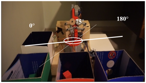
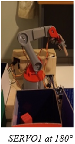
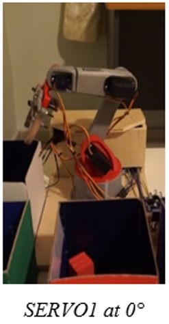
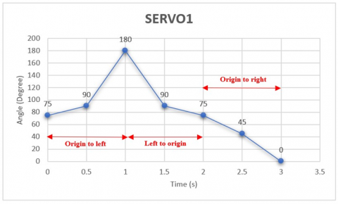
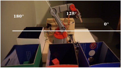
The experiment was conducted for all 6 Degree of Freedom (DOF) of the Robot arm which includes all six servo motors. The first experiment is to manually control the robot arm movement according to the user’s input angle through the Wi-Fi-Blynk apps. This experiment is carried out to conclude that the robot arm responded corresponding to the instructions (commands) given by the user through the Blynk Graphic User Interface (GUI). Figure 8 shows the initial angular position of the servo1 angle and the corresponding graph for each servo motors is shown in Figure 9 during the positioning of each robot arms at a certain angle. As can be seen in Figure 9, the initial angle for servo1 is at 75° which represents the origin. Then, the user gives command through the Blynk apps to turn to the left which is set at180°. Next, from this position, the robot is instructed to go back to its original 75° position before turning to the right at 0°. Table 1 shows the final position of the servo1 motor accordingly.
Figure 8. Servo1 origin position (75°)
Table 1. Initial & Final Position of Servo 1
|
Angle/Position |
180° / Left |
0° / Right |
|
Robot Arm Final Position |
Figure 9. SERVO1 Angle versus Time
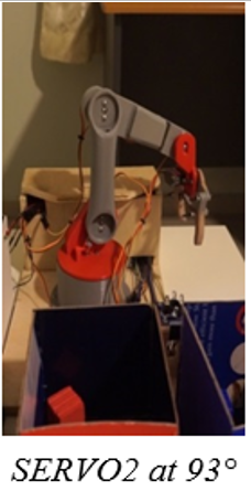
Figure 10 shows the original angle position of servo2 and its corresponding graph is shown in Figure 11 when it is positioned at a certain angle. As can be seen in Figure 10, the initial angle for servo2 is at 125° which represents the starting point. Then, the user gives command through the Blynk apps to lift up the arm which is set at 150°. Next, from this position, the robot is instructed to go back to its original 125° position before being lifted down to 93°. Table 2 shows the final position of the servo1 motor.
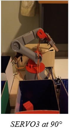
Figure 12 shows the original angle position of servo3 and its corresponding graph is shown in Figure 13, positioned at a certain angle. As can be seen in Figure 10, the initial angle for servo3 is at 70° which represents the starting point. Then, the user gives the command through the Blynk apps to lift the arm up which is set at 30°. Next, from this position, the robot is instructed to go back to its original 70° position before lifted down to 90°. Table 3 shows the final position of the servo1 motor.
Figure 10. SERVO2 Origin position (125°)
Figure 11. SERVO2 Angle versus Time
Table 2. Initial & Final Position of Servo 2
|
Angle/Position |
150° / Up |
93° / Down |
|
Robot Arm Final Position |
Figure 12. SERVO3 Origin Position (70°)
Figure 13. SERVO3 Angle versus Time
Table 3. Initial & Final Position of Servo 3
|
Angle/Position |
30° / Up |
90° / Down |
|
Robot Arm Final Position |
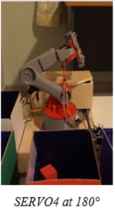
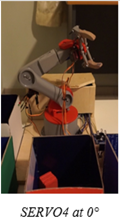
Figure 14. SERVO4 Origin Position (90°)
Figure 15. SERVO4 Angle versus Time
Table 4. Initial & Final Position of Servo 4
|
Angle/Position |
180° / Right |
0° / Left |
|
Robot Arm Position |
Figure 14 shows the original angle position of servo4 and its corresponding graph is shown in Figure 15, positioned at a certain angle. As can be seen in Figure 14, the initial angle for servo4 is at 90° which represents the starting point. Then, the user gives a command through the Blynk apps to turn right, which is set at 180°. Next, from this position, the robot is instructed to go back to its original 90° position before turning left to 0°. Table 4 shows the final position of the servo1 motor.
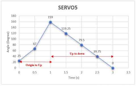
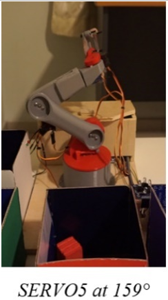
Figure 16 shows the original angle position of servo5 and its corresponding graph is shown in Figure 17, positioned at a certain angle. As can be seen in Figure 16, the initial angle for servo5 is at 25° which represents the starting point. Then, the user gives a command through the Blynk apps to lift the arm up which is set at 159°. Next, from this position, the robot is instructed to go back to its original 25° position before being turned down to 0°. Table 5 shows the final position of the servo1 motor.
Figure 16. SERVO5 Origin Position (25°)
Figure 17. SERVO5 Angle versus Time
Table 5. Initial & Final Position of Servo 5
|
Angle/Position |
159° / Up |
0° / Down |
|
Robot Arm Final Position |
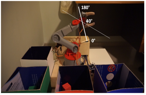
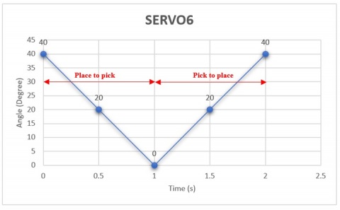
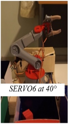
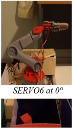
Figure 18 shows the original angle position of servo6 and its corresponding graph is shown in Figure 19, positioning at a certain angle. Servo6 is located at the tip of the robot arm which performs the pick and place function. As can be seen in Figure 18, the initial angle for servo6 is at 40° which represents the starting point (place item). Then, the user gives a command through the Blynk apps to pick (hold) the item which was set at 0° before instructed it to go back to place (release) the item back at 40°. Table 6 shows the final position of the servo6 motor.
Table 7 demonstrates the steps and the actions of the robot arm when the color sorting automatic mode is activated in the Blynk Graphic User Interface (GUI). The robot arm able to sense and detect up to three colors which are green, red & blue. The robot will detect the blocks present and sorts into the correct colors bin based on the blocks color.
Figure 18. SERVO6 Origin Position (40°)
Figure 19. SERVO6 Angle versus Time
Table 6. Initial & Final Position of Servo 6
|
Angle/Position |
40° / Place |
0° / Pick |
|
Robot Arm Final Position |
Through the experiments, we found out the correct recognition rate of this robotic arm is not 100% but normally will work pretty well. Factors that cause the failure of the recognition are as below:
Table 7. Steps & Action of the Robot Arm in Color Sorting Automatic Mode
|
STEP |
ACTIONS |
SYSTEM / ROBOT ARM DEMONSTRATION |
|
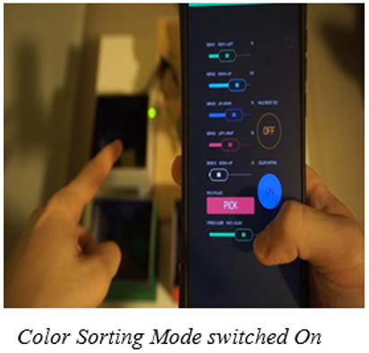
1 |
Automatic Color Sorting Mode switched on and the Sensor Box Green LED ON indicates that the Color Sorting is ready. |
|
|
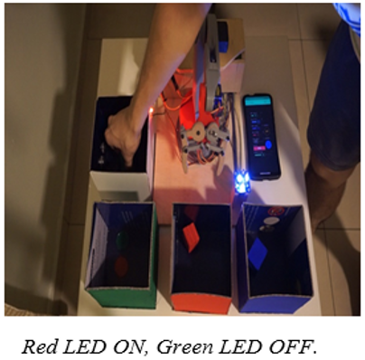
2 |
A green color block is placed into the sensor box. The Sensor Box detects the presence of the block. Red LED ON, Green LED OFF. |
|
|
3 |
The picking process begins. |
|
|
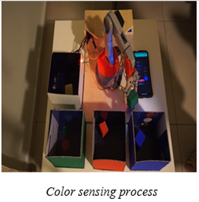
4 |
The block is being transferred by the robot’s arm from the sensor box to the color sensor. Block Color sensing process ongoing. |
|
|
5 |
The block is sorted according to the correct color box and the robot arm releases the block. |
After the testing and installation have been completed, it is found that each servo motors of the entire Robot Arm system will undergo a short jittering and vibration every 2 seconds. By conducting a wide-ranging analysis, it was found that the main problem of the servo jittering is caused by the conflict or interruption of the Servo.h library and the Software Serial library. The jittering affects the entire system by resetting or turning the voltage from 5V to 0V in a very short period and causes the failure of the input sensors to operate well. The input data value will reset to the initial position and causes the sorting task to become inaccurate. Hence, the PWM motor programming style is applied to solve this problem. Figures 20 & 21 show the coding that is used to determine the time needed for the Servo Motor to rotate to the specific angle needed.
The PWM Servo Control causes another consequence because it turns off the Servo Motor after the cycle or time is completed. This causes some parts of the Servo Motor to fail to overcome the weight of the entire Robot Arm. Hence, another method is to use a timer register for the PWM pin to enable the Arduino to control the Servo Motor without turning off and to ensure that the Servo Motor is powering when the Robot Arm is activated. This solution is designed which different from the others researches that using external drivers or interface to overcome this problem. The following figures illustrate the coding style used for SERVO2 (OC1B), SERVO3 (OC1A) & SERVO6 (OC2A).
Figure 20. PWM Cycle Principle
Figure 21. TIMER1 & TIMER2 Register Coding
Through an extensive design process, the system has been designed to successfully perform the pick and place functions for a color sorting robot arm using the wireless Blynk apps. The wireless control color sorting robot arm has been implemented with minimize jittering issue which causes by the number of servo motors used and the combination of dual function in one of the robot systems. The extensive pulse signal transfer will cause the robot to be not stable and external drivers is needed to overcome it. Hence, this research is carried out to shows the dual function wireless control color sorting robot arm can be perform smoothly and stable by using only one Arduino microcontroller. The robot system provides up to 90% of color recognization rate which is much higher and can be categorized as nearly zero defects in industrial rating. Periodical testing for quality assurance is a must to ensure that there is no problem and to determine the success of the design. The enhancement that should be done in this project is highly related to machine learning and Artificial Intelligent that are available on the market. For future work, it is recommended that the input power from the wired input to the battery is increased to make it portable and to ensure that the servo motors become more stable and able to carry a heavier load.
The work presented in this paper has been supported by the Faculty of Electrical and Electronics Engineering, University Malaysia Pahang, with the assistance of Grant RDU190320.
[1] Amin, U., Ahmad, G., Liaqat, N., Ahmed, M., Zahoor, S. (2014). Detection & distinction of colors using color sorting robotic arm in a pick & place mechanism. International Journal of Science and Research, 3(6): 1164-1168.
[2] Ghiet, A.M.A., Baba, A. (2017). Robot Arm Control with Arduino. University of Turkish Aeronautical Association, p. 42.
[3] Högfeldt, S.A., Söderman, D. (2016). Human controlled robotic arm: Improving usability with haptic feedback. Degree Project in Technology, First Cycle, 15 Credits Stockholm, Sweden.
[4] Faravar, A. (2014). Design, implementation and control of a robotic arm using PIC 16F877A microcontroller. Institute of Graduate Studies and Research, Eastern Mediterranean University, Gazimağusa, North Cyprus.
[5] Muhammed, J.N.K, John, N., Fayas, M., Mohan, M., Sajeev, M., Safwan, C.N. (2007). Wireless control of pick and place robotic arm using an android application. International Journal of Advanced Research in Electrical, Electronics and Instrumentation Engineering, 4(4): 2410-2416. https://doi.org/10.15662/ijareeie.2015.0404055
[6] Behera, S.K. (2015). Wireless controlled robotic automation system. MTech Thesis.
[7] Kiat, W.P. (2015). Wireless Controlled Robot with Hand for Dangerous Task. Final Year Project, UTAR. http://eprints.utar.edu.my/id/eprint/1821.
[8] Reddy, D.V.K. (2014). Sorting of objects based on colour by pick and place robotic arm and with conveyor belt arrangement. International Journal of Mechanical Engineering and Robotics Research, 3(1): 67-74.
[9] Thike, A., San, Z.Z.M., Oo, Z.M. (2019). Design and development of an automatic color sorting machine on belt conveyor. International Journal of Science and Engineering Application, 8(7): 176-179.
[10] Nkomo, M., Collier, M. (2012). A color-sorting SCARA robotic arm. In 2012 2nd International Conference on Consumer Electronics, Communications and Networks (CECNet), Yichang, pp. 763-768. https://doi.org/10.1109/CECNet.2012.6201967
[11] Szabo, R., Lie, L. (2012). Automated colored object sorting application for robotic arms. In 2012 10th International Symposium on Electronics and Telecommunications, Timisoara, pp. 95-98. https://doi.org/10.1109/ISETC.2012.6408119
[12] Apriaskar, E., Fauzi, M.R. (2020). Robotic technology towards industry 4.0: Automatic object sorting robot arm using Kinect sensor. In Journal of Physics: Conference Series, 1444: 012030.
[13] Sheth, S.M., Kher, R.K., Shah, R., Dudhat, P., Jani, P. (2010). Automatic sorting system using machine vision. In Multi-Disciplinary International Symposium on Control, Automation & Robotics, DDIT, Nadiad, Vol. 1. https://doi.org/10.13140/2.1.1432.1448
[14] Khan, S.A., Anika, T.Z., Sultana, N., Hossain, F., Uddin, M.N. (2019). Color sorting robotic arm. In 2019 International Conference on Robotics, Electrical and Signal Processing Techniques (ICREST), Dhaka, Bangladesh, pp. 507-510. https://doi.org/10.1109/ICREST.2019.8644167
[15] Ata, A.A., Rezeka, S.F, El-Shenawy, A., Diab, M. (2013). Design and development of 5-DOF color sorting manipulator for industrial applications. World Academy of Mechanical Science and Engineering, 84: 380-387.
[16] Wali-ur-Rahman, M., Ahmed, S.I., Hossain, R.I., Ahmed, T., Uddin, J. (2018). Robotic Arm with Proximity and Color Detection. 2018 IEEE 7th International Conference on Power and Energy (PECon), Kuala Lumpur, Malaysia, pp. 322-326. https://doi.org/10.1109/PECON.2018.8684066
[17] Harish, K., Megha, D., Shuklambari, M., Amit, K., Jambotkar, C..K. (2017). Pick and place robotic arm using arduino. International Journal of Science, Engineering and Technology Research, 6(12): 1568-1573.
[18] Purdum, J. (2015). Beginning C for Arduino. Apress, Berkeley, CA. https://doi.org/10.1007/978-1-4842-0940-0
[19] Lienig, J., Bruemmer, H. (2017). Recycling requirements and design for environmental compliance. In Fundamentals of Electronic Systems Design, Springer, Cham, pp. 193-218. https://doi.org/10.1007/978-3-319-55840-0_7
[20] Will Robots and AI Take Your Job? The economic and political consequences of automation [Online]. Available: https://www.brookings.edu/blog/techtank/2018/04/18/will-robots-and-ai-take-your-job-the-economic-and-political-consequences-of-automation/, accessed on Oct. 17, 2020.
[21] How Servo Motor Works & Interface It with Arduino - Last Minute Engineers [Online]. Available: https://lastminuteengineers.com/servo-motor-arduino-tutorial/, accessed on Oct. 30, 2020.
[22] Arduino Color Sensor TCS230 TCS3200 | Random Nerd Tutorials [Online]. Available: https://randomnerdtutorials.com/arduino-color-sensor-tcs230-tcs3200/, accessed on Oct. 25, 2020.