Fayçal Mehedi* | Habib Benbouhenni | Lazhari Nezli | Djamel Boudana
© 2021 IIETA. This article is published by IIETA and is licensed under the CC BY 4.0 license (http://creativecommons.org/licenses/by/4.0/).
OPEN ACCESS
In this work, the direct torque control (DTC) is applied to the five-phase permanent magnet synchronous motor (FP-PMSM). The DTC method based on classical space vector pulse width modulation (SVPWM) is a common solution used to overcome traditional problems; such as stator flux ripple, electromagnetic torque ripple and gives more total harmonic distortion (THD) of the stator current. The actual paper is based on improving the performance of DTC-SVPWM by using the feedforward neural networks (FNNs) instead of the proportional-integral (PI) regulators and hysteresis comparators (HCs) of the conventional SVPWM strategy. This algorithm can solve the traditional PI regulators and HCs problems which are represented in responses dynamic and reduce the torque ripple, flux ripple, and the THD of stator current of FP-PMSM drives. The proposed strategy was tested in different tests with simulation using Matlab software.
DTC, FP-PMSM, SVPWM, FNNs, PI, THD
In multi-phase motors (MPMs), the five-phase permanent magnet synchronous motor (FP-PMSM). It is the most used and famous. This type of motor provides greater torque than conventional electric motors. Among the characteristics of these electric motors, we mention: lowering of the stator current per phase, reduced electromagnetic torque ripples, improved fault tolerance, greater efficiency, and minimized stator flux ripples compared to three-phase PMSMs (TP-PMSMs) [1, 2]. Despite these positives, the FP-PMSMs are quite large, and controlling it is very difficult compared to TP-PMSMs.
To control electrical machines there are several different types of controls. The most famous of them is direct torque control (DTC). This strategy was first introduced to control induction motors in the early 1980s. Among the characteristics of this type is that it is very simple and inexpressive materials and improves the performances of the electric motor. Compared with the field-oriented control (FOC), the DTC control is best in all respects. However, this method has several disadvantages, as is all other controls. Among its drawbacks are the following: frequent electromagnetic torque and stator flux ripples, the values of total harmonic distortion (THD) are great, fall in electromagnetic torque in the event of low frequencies and it is affected by the change of the parameters of the electric motor [3, 4]. Several articles addressed the negatives of the DTC method, using the latest technologies. Among these new technologies, we mention the following: fuzzy logic (FL), sliding mode controller (SMC), multi-level inverter (MLI), space vector pulse width modulation (SVPWM), artificial neural networks (ANNs), super-twisting sliding mode algorithm (STSM), adaptive-network-based fuzzy inference system algorithm (ANFIS), Second-order sliding mode control (SOSMC) and genetic algorithm (GA).
A new DTC control based on the ANN controller was proposed to control the induction motor (IM) [3]. The seven-level hysteresis comparator (HC) of the DTC control was proposed based on the ANN [5]. A new DTC method was proposed to regulate the stator flux and electromagnetic torque of IM drives, where the switching table (ST) is replaced by the ANN algorithm and the proportional-integral (PI) controller of speed was replaced by the FL controller [6]. This proposed method is robust and reduced the THD value of stator current compared to classical DTC. DTC control of PMSM was proposed for low-speed operation [7]. The 3-phase IM drive is controlled by sensorless DTC control using the ANN selector table [8]. Four-level DTC-ANN control based on the ANFIS controller of speed is designed to control the IM drives [9]. A novel DTC strategy using STSM was proposed to control a DFIG [10]. SMC algorithm and FL controller are combined to minimize the torque and stator flux ripple of the IM controlled by DTC control [11]. The neural DTC-STSM method is proposed to regulate the active and reactive powers of the DFIG based wind turbines [12]. Five-level DTC control based on fuzzy logic is proposed to control the IM drives, where the torque HC was replaced by the fuzzy controller. This proposed strategy is a simple structure and minimizes the torque ripple compared to the traditional DTC control [13]. DTC with neural ST minimized the torque ripples of IM compared to DTC with fuzzy PI of speed and DTC method with neural HCs [14]. Speed control of FP-PMSM through fractional integral terminal sliding mode control (FITSMC), SMC, and PI controller is presented [15]. The authors [16] propose a DTC-ANN method with ANFIS controller of speed for IM fed by 3-level NPC inverter, where a comprehensive analysis is provided. A hybrid control was proposed based on ANN and ANFIS of the DTC to control IM [17]. The authors [18] propose a Dual DTC for DFIM using ANN. A novel STs of 12 sectors DTC was proposed for IM drive [19]. Four-level DTC based on the ANN algorithm was proposed to control 3-phase PMSM using neural PI of speed [20].
On the other hand, some papers deal with DTC of MPMs, among them: a novel DTC method is proposed to control five-phase induction motor (FPIM) using open-phase fault [21]. Classical DTC strategy is proposed to regulate the stator flux and electromagnetic torque of the FPIM drives [22]. DTC strategy with common-mode voltage is proposed to minimize the current harmonics of FPIM [23]. A modified DTC strategy was proposed to control FPIM drives [24]. DTC method and FL controller are combined to regulate the torque of FPIM [25]. The FPIM drive is controlled by the DTC-SVM method using the MRAS estimator [26]. ANNs algorithm and DTC-SVM method are combined to regulate the flux/torque of FPIM, where the PI controllers of the DTC-SVM are replaced by ANN algorithms and this proposed DTC control improved 17% the performances of FPIM compared to DTC with PI controllers [27]. DTC method with a sinusoidal stator current waveform was proposed to regulate the current of FP-PMSM [28]. DTC technique with load capacity enhancement was proposed to control FP-PMSM drives [29]. DTC technique with optimized vector tables of FP-PMSM is introduced [30]. Modified ST of DTC strategy controlled six-phase PMSM drives [31]. DTC-SVM strategy was proposed to control the FP-PMSM by using the biogeography based optimization (BBO) algorithm [32].
In this work, the DTC-SVPWM system with the application of the feedforward neural networks (FNNs) algorithms has been considered. The original contribution of this work is the application of the FNN algorithms in the DTC-SVPWM system with FP-PMSM and simulation investigation of this new structure.
This work is divided into seven sections. The 5-phase neural SVPWM strategy has been discussed in Section 2. In Section 3, the classical DTC method of the FP-PMSM is described. In Section 4, the DTC-SVPWM technique is presented. Section 5 deals with the description of the DTC-SVPWM technique with the application of FNN algorithms. Simulation studies are presented and discussed in Section 6. The work is concluded with a summary.
The SVPWM technique is based on the principles of the spatial vector for the control of pulse width modulation (PWM) and requires a calculation of the sector and time duration [33]. It is mainly used for AC machines. In this paper, we propose a simple strategy of five-phase SVPWM based on calculating the voltages min, max (Va, Vb, Vc, Vd, and Ve) and find the switching states. Figure 1 shows the principle of the five-phase SVPWM strategy of the 2-level inverter. On the other hand, a new SVPWM strategy based on FNN (NSVPWM) is proposed to control the 2-level inverter of the FP-PMSM. The principle of the NSVPWM strategy is similar to the conventional SVPWM technique simplified [34]. The difference lies in replacing the HC with a neural controller. Figure 2 shows the principle of the five-phase NSVPWM strategy. This proposed NSVPWM strategy reduced the flux ripples, torque ripples and the THD value. The FNNs algorithm consists of 3 layers: hidden layers (HL), input layers (IL) and output layers (OL). Each layer is made up of several neurons [34].
Figure 1. Five-phase SVPWM strategy
Figure 2. Five-phase NSVPWM strategy
To make the five-phase NSVPWM strategy, we used the gradient descent w/momentum & adaptive LR backpropagation (W/MALRB). This technique is a network learning function that updates bias and weight values according to gradient descent with an adaptive training rate. Figure 3 shows the structure of the FNNs of HC used in the Five-phase NSVPWM technique, which consists of 8 neurons in the HL, neurons in the OL, and a linear input node.
The gradient descent W/MALRB has 2 layers, layer 1, and layer 2. The HL is given in Figure 4. The parameters of the gradient descent W/MALRB algorithms are shown in the Table 1.
Figure 3. Structure of FNNs of the HC
Figure 4. Structure of the hidden layer
Table 1. Parameters of the gradient descent W/MALRB algorithm
|
Parameters |
Values |
|
TrainParam.eposh |
600 |
|
Functions of activation |
Tensing, Purling, gensim |
|
Number of layer 1 |
1 |
|
Number of layer 2 |
1 |
|
Number of hidden layers |
1 |
|
Number of neurons in layer 1 |
2 |
|
Number of neurons in layer 2 |
1 |
|
Number of neurons in HL |
8 |
|
Performances |
Mean Squard Error (mse) |
|
TrainParam.mu |
0.8 |
|
Coefficient of acceleration of convergence (mc) |
0.9 |
|
TrainParam.Lr |
0.005 |
|
TrainParam.goal |
0 |
|
TrainParam.show |
50 |
Traditionally, DTC control is robust and simple control scheme used to control any machines. This strategy of control is based on the ST to control the inverter. The latter feeds the electric motor. In our article, we will pay attention to FP-PMSM. In DTC control, we use the 3-level HCs to control the torque and 2-level HCs to control the stator flux. The sector level is 10. On the other hand, mathematical equations of an FP-PMSM are expressed in the park reference (d-q-x-y) [2]:
The stator voltage:
$\left\{ \begin{align} & v_{ds}^{{}}={{R}_{s}}i_{ds}^{{}}+\frac{d}{dt}\Phi _{ds}^{{}}-{{w}_{r}}\Phi _{qs}^{{}} \\ & v_{qs}^{{}}={{R}_{s}}i_{qs}^{{}}+\frac{d}{dt}\Phi _{qs}^{{}}+{{w}_{r}}{{\Phi }_{ds}} \\ & v_{xs}^{{}}={{R}_{s}}i_{xs}^{{}}+\frac{d}{dt}\Phi _{xs}^{{}} \\ & v_{ys}^{{}}={{R}_{s}}i_{ys}^{{}}+\frac{d}{dt}\Phi _{ys}^{{}} \\ & v_{0s}^{{}}={{R}_{s}}i_{0s}^{{}}+\frac{d}{dt}\Phi _{s0}^{{}} \\\end{align} \right.$ (1)
The magnetic equations:
$\left\{ \begin{align} & \Phi _{ds}^{{}}={{L}_{d}}i_{ds}^{{}}+{{\varphi }_{f}} \\ & \Phi _{qs}^{{}}={{L}_{q}}i_{qs}^{{}} \\ & \Phi _{xs}^{{}}={{L}_{ls}}i_{xs}^{{}} \\ & \Phi _{ys}^{{}}={{L}_{ls}}i_{ys}^{{}} \\ & \Phi _{s0}^{{}}={{L}_{ls}}i_{0s}^{{}} \\\end{align} \right.$ (2)
For the FP-PMSM, the expression of the electromagnetic torque is:
$T_{e m}=\frac{5}{2} P\left(\left(L_{d}-L_{q}\right) i_{d s} i_{q s}+\phi_{f} i_{q s}\right)$ (3)
The dynamic equation is:
$J \frac{d w_{r}}{d t}=p T_{e m}-p T_{r}-f w_{r}$ (4)
The main objective of the DTC strategy is to directly control Φs and Tem. The flux and torque are controlled quantities. The errors between the reference values (Φs* and Tem*) and the actual values (Φs and Tem) are introduced into two HC which determine the switching state of the switch. In classical DTC method, the switching table of multi-phase machine is proposed by Listwan and Krzysztof [26]. This table contains the error flux εΦs, the error torque εTem, and the sector number (S1,..S10). The optimal vector stator voltage of the FP-PMSM is presented in Table 2 [35].
Table 2. Switching table of the classical DTC of FP-PMSM
|
εΦs |
εTem |
S1 |
S2 |
S3 |
S4 |
S5 |
S6 |
S7 |
S8 |
S9 |
S10 |
|
1 |
-1 |
17 |
25 |
24 |
28 |
12 |
14 |
6 |
7 |
3 |
19 |
|
1 |
24 |
28 |
12 |
14 |
6 |
7 |
3 |
19 |
17 |
25 |
|
|
0 |
0 |
31 |
0 |
31 |
0 |
31 |
0 |
31 |
0 |
31 |
|
|
0 |
-1 |
7 |
3 |
19 |
17 |
25 |
24 |
28 |
12 |
14 |
6 |
|
1 |
14 |
6 |
7 |
3 |
19 |
17 |
25 |
24 |
28 |
12 |
|
|
0 |
31 |
0 |
31 |
0 |
31 |
0 |
31 |
0 |
31 |
0 |
The stator flux components can be written by the stator currents and the voltage in the reference frame (α, β):
$\left\{\begin{array}{l}\Phi_{\alpha}=\int\left(v_{\alpha}-R_{s} i_{\alpha}\right) d t \\ \Phi_{\beta}=\int\left(v_{\beta}-R_{s} i_{\beta}\right) d t\end{array}\right.$ (5)
The amplitude of the stator flux is determined by:
$\Phi_{s}=\sqrt{\Phi_{\alpha}{ }^{2}+\Phi_{\beta}{ }^{2}}$ (6)
The torque formula of the FP-PMSM is expressed in terms of flux and stator current as:
$T_{e}=\frac{5}{2} P\left(\Phi_{\alpha} i_{\beta}-\Phi_{\beta} i_{\alpha}\right)$ (7)
Position of the stator flux:
$\theta_{s}=\tan ^{-1} \frac{\Phi_{\beta}}{\Phi_{\alpha}}$ (8)
The disadvantage of the traditional DTC command is the use of the ST and the CHs. To improve the performance of this control technique, we offer a new control structure based on SVPWM simplified. This proposal consists of replacing the CHs and the ST by 2 PI regulators and an SVPWM algorithm.
The block diagram of the DTC-SVPWM applied to FP-PMSM is shown in Figure 5.
Figure 5. Diagram of DTC-SVPWM of the FP-PMSM
The stator flux equations of the FP-PMSM in the stationary reference x,y frame are expressed as [35]:
$\left\{\begin{array}{l}v_{x s}=R_{s} i_{x s}+\frac{d}{d t} \Phi_{s} \\ v_{y s}=R_{s} i_{y s}+\frac{d}{d t} \Phi_{s}\end{array}\right.$ (9)
The torque can be expressed as:
$T_{e m}=\frac{5}{2} p \Phi_{s} i_{y}$ (10)
From (9) and (10), the flux and torque of the FP-PMSM can be expressed as:
$\left\{\begin{array}{l}\frac{d}{d t} \Phi_{s}=v_{x s}-R_{s} i_{x s} \\ T_{e m}=\frac{5}{2 R_{s}} p \Phi_{s}\left(v_{y s}-w_{r} \Phi_{s}\right)\end{array}\right.$ (11)
In this control structure, the Tem* value and the amplitude of Φs* are compared respectively to the Tem and Φs values. The error flux εΦs and the error torque εTem are sent to the PI regulators, which generate the voltage components (vxs, vys).
DTC using PI regulators is a traditional technique used to control FP-PMSM. However, PI regulators for application to an FP-PMSM have some drawbacks, where this technique gives more flux and torque ripples and thus reduces the robustness of the system. The VC technique based on the hybrid control of an FP-PMSM has been proposed [36], where the PI controller of the speed of an FP-PMSM has been replaced by an FLC and SMC controller. The DTC based on an SVM using the FL algorithm is proposed to minimize the flux and torque ripple of the FP-PMSM [37]. The authors [35] used a DTC-SVM technique for the FP-PMSM drive, where the PI controllers of the speed are replaced by SMC algorithms and this proposed DTC control improved the performances of systems compared to DTC with PI controllers.
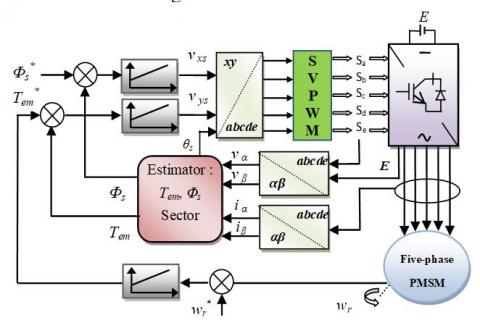
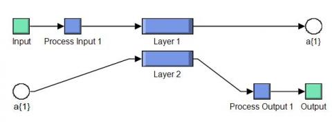
In this part, the DTC based on the FNNs of the FP-PMSM drive was proposed, where the SVPWM was replaced by the NSVPWM technique and the PI regulators of the flux, speed and torque were replaced by the FNNs algorithm. This proposed new DTC structure is a simple command and easy to implement. The block diagram of the NDTC-NSVPWM applied to FP-PMSM is shown in Figure 6.
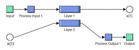
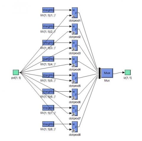
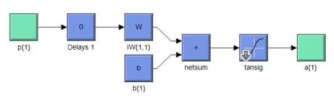
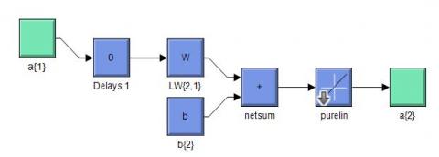
The structure of the FNNs controller is shown in Figure 7. On the other hand, the gradient descent W/MALRB characteristic and the training performance of the rotor speed are shown in Figure 9 and Figure 10. The FNNs consists of an IL comprises 02 neurons (See Figure 8); one HL has 06 neurons (See Figure 11), and an OL 01 neuron (See Figure 12).
Figure 6. Block diagram of the NDTC-NSVPWM applied to FP-PMSM
Figure 7. Block diagram of FNNs
Figure 8. Layer 1
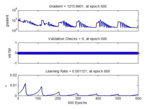
Figure 9. The gradient descent W/MALRB characteristic
Figure 10. Training performance
Figure 11. Block diagram of HL
Figure 12. Layer 2
The simulation model is developed in a Matlab/Simulink. The FP-PMSM parameters are as follows: P=2, Rs=0.7 Ω, f=0.005 Nm/rad.s, ϕf=0.5 web, J= 0.0025 Kg/m2, Ld =0.0018 H, Lq=0.0042 H [35]. Three control structures: NDTC-NSVPWM, DTC-SVPWM and DTC-ST are compared and discussed to test the robustness and performance of the system.
6.1 Performance tests
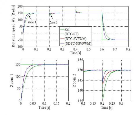
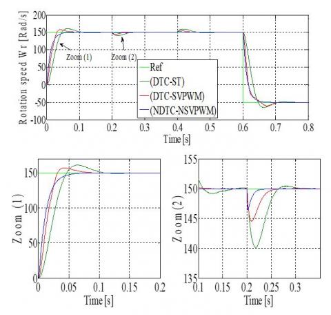
To test the performance of the proposed DTC strategy for FP-PMSM, we apply a resistance torque Tr =10 Nm at t = [0.2s, 0.4s]. The reversal of rotation from 150 rad/s to -50 rad/s at t=0.6s. In Figure 13, the proposed control schemes response time is very fast compared to the DTC-SVPWM and DTC-ST control. Besides, a speed disturbance rejection (approximately 3% of NDTC-NSVPWM method).
Figure 13. Rotation speed
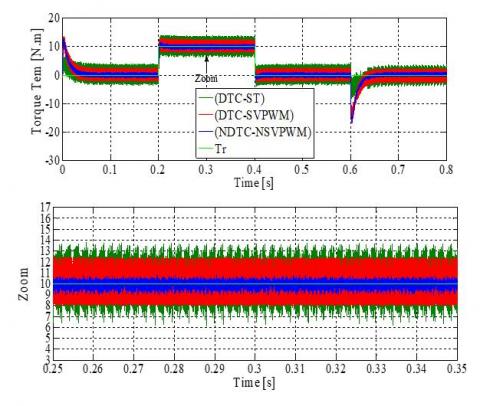
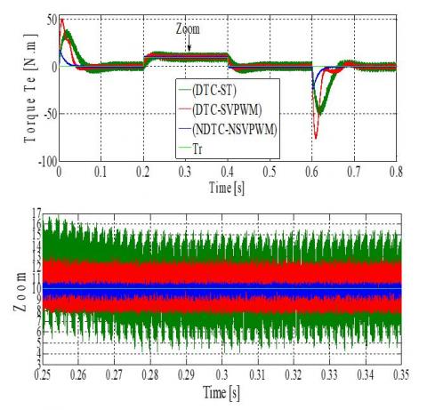
Figure 14 illustrates that the Tem returns to 0N.m at the end of the transitory mode. For the proposed DTC strategy, we also observe that when the introduction of a Tr at t=0.2s the Tem follows its reference value and reduced torque ripple compared to DTC-SVPWM and DTC-ST. A comparative study is presented in Table 3.
Figure 14. Electromagnetic torque
Table 3. Amplitude of ripples
|
|
NDTC-NSVPWM |
DTC-SVPWM |
DTC-ST |
|
Torque ripples |
8.9-10.7 (1.8 Nm) |
8-12.1 (4.1 Nm) |
6.2-13.6 (7.4 Nm) |
|
Flux ripples |
0.398-0.401 (0.003 Wb) |
0.397-0.403 (0.006 Wb) |
0.393-0.407 (0.014 Wb) |
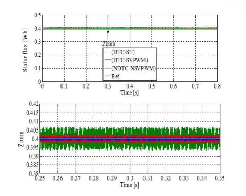
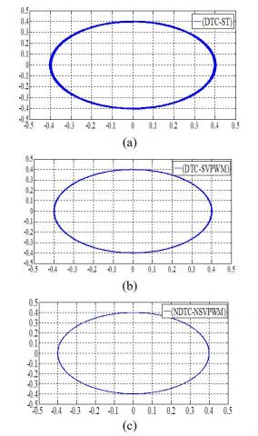
Figure 15 shows the stator flux response. The NDTC-NSVPWM method can reduce flux ripples and improve system performance (see Table 3). The trajectories in the α-β axis of the stator flux vector for the three strategies are presented in Figure 16.
Figure 15. Stator flux
Figure 16. Trajectories in α-β axis of the stator flux vector when: (a) DTC-ST, (b) DTC-SVPWM, (c) NDTC-NSVPWM
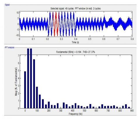
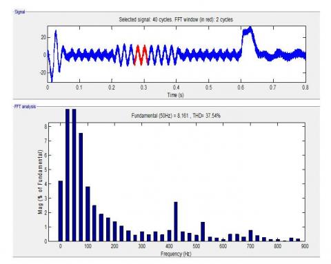
Figure 17. Phase a current THD (DTC-ST)
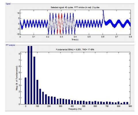
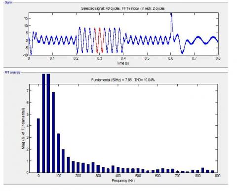
Figure 18. Phase a current THD (DTC-SVPWM)
Figure 19. Phase a current THD (NDTC-NSVPWM)
Figures 17-19 represents the THD of the one phase stator current of FP-PMSM using the FFT method for the three strategies. We can clearly see that THD is minimized using the NDTC-NSVPWM (THD=9.49%) compared to DTC-SVPWM (THD=17.43%) and DTC-ST (THD=27.37%).
6.2 Robustness test
To evaluate the robustness of the proposed DTC strategy, the nominal value of the Lq and Ld are reduced by 30%, J, and Rs are increased by 150%. The results of the simulation are represented in Figures 20-25. These variations have a clear effect on electromagnetic torque, stator flux, and speed response. The effect appears to be greater for the DTC-SVPWM and the DTC-ST technique compared to the NDTC-NSVPWM method (see Table 4). On the other hand, the THD value of stator current in the NDTC-NSVPWM strategy has been greatly reduced. A comparative study is presented in Table 5. Thus, it can be concluded that the NDTC-NSVPWM strategy is more robust than the DTC-SVPWM and the DTC-ST technique.
Figure 20. Rotation speed
Figure 21. Electromagnetic torque
Figure 22. Stator flux
Figure 23. Phase a current THD (DTC-ST)
Figure 24. Phase a current THD (DTC-SVPWM)
Figure 25. Phase a current THD (NDTC-NSVPWM)
Table 4. Amplitude of ripples
|
|
NDTC-NSVPWM |
DTC-SVPWM |
DTC-ST |
|
Torque ripples |
8.7-10.9 (2.2 Nm) |
7.5-12.9 (5.4 Nm) |
4.2-15.6 (11.4 Nm) |
|
Flux ripples |
0.397-0.402 (0.005 Wb) |
0.395-0.405 (0.010 Wb) |
0.389-0.410 (0.021 Wb) |
Table 5. Comparative of THD [%]
|
|
|
THD [%] |
|
|
|
NDTC-NSVPWM |
DTC-SVPWM |
DTC-ST |
|
Stator current |
10.04 |
20.52 |
37.54 |
In this work, a novel structure of DTC based on FNNs of the FP-PMSM drive fed by an NSVPWM inverter is presented. The proposed control design to improve the performance and robustness of the DTC method. The simulation results confirmed the good static and dynamic performance, the reduction of stator flux ripples, torque ripples, and robustness of the proposed control structure compared to the DTC-SVPWM and conventional DTC. Indeed, we proposed a new modulation 5-phase NSVPWM strategy; it was clear in the stator current THD that the use of the NSVPWM minimizes the THD more and more than the traditional SVPWM and PWM technique. Therefore, the NDTC-NSVPWM structure is simple and easy to implement.
|
FP-PMSM |
Five-phase permanent magnet synchronous motor |
|
DTC |
Direct torque control |
|
NDTC |
Neural direct torque control |
|
ANN |
Artificial neural network |
|
W/MALRB |
gradient descent W/momentum & adaptive LR backpropagation |
|
SVPWM |
Space vector pulse width modulation |
|
FNNs |
Feedforward neural networks |
|
NSVPWM |
Neural space vector pulse width modulation |
|
THD |
Total harmonic distortion |
|
PI |
Proportional-Integral |
|
Rs |
Stator resistance |
|
vs |
Stator voltages |
|
Ld, Lq |
stator inductance in d and q axis |
|
ϕf |
Magnetic flux |
|
is |
Stator currents |
|
f |
Viscous damping |
|
p |
Number of pairs poles |
|
Lx, Ly |
x and y axis stator inductance |
|
J |
Inertia moment |
|
Greek symbols |
|
|
Tem |
Electromagnetic torque |
|
θs |
Position of the stator flux |
|
Tr |
Load torque |
|
Φs |
Stator flux |
|
θr |
Electrical angle |
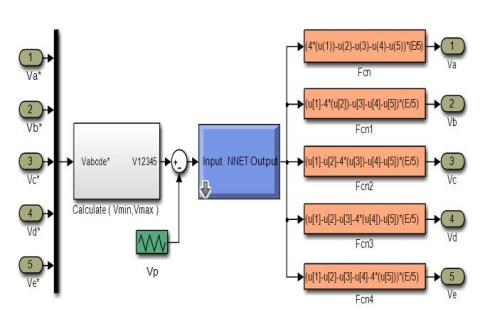
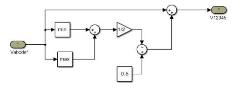
1. Block diagram of the SVPWM
The block diagram of calculating the maximum and minimum voltages is shown in Figure 26.
Figure 26. Block diagram of calculate the voltages
[1] Hosseyni, A., Trabelsi, R., Mimouni, M.F., Iqbal, A. (2018). Fault tolerant vector controlled five-phase permanent magnet synchronous motor drive with an open phase. IEEE International Multi-Conference on Systems, Signals & Devices (SSD), Hammamet, Tunisia, pp. 780-784. http://dx.doi.org/10.1109/SSD.2018.8570487
[2] Mehedi, F., Nezli, L., Mahmoudi, M.O., Boudjema, Z. (2017). Second order sliding mode control of two series-connected multi-phase permanent magnet synchronous motor. The Mediterranean Journal of Measurement and Control, 13(3): 795-804. http://dx.doi.org/10.1109/CISTEM.2018.8613341
[3] Benbouhenni, H. (2018). Improved switching selection for DTC of induction motor drive using artificial neural networks. Acta Electrotechnica et Informatica, 18(1): 26-34. http://dx.doi.org/10.15546/aeei-2018-0004
[4] Tabrizchi, A.M., Soltani, J., Shishehgar, J., Abjadi, N.R. (2019). Direct torque control of speed sensorless five-phase IPMSM based on adaptive input-output feedback linearization. The 5th Annual International Power Electronics, Drive Systems and Technologies Conference (PEDSTC), Tehran, pp. 43-48. http://dx.doi.org/10.1109/PEDSTC.2014.6799341
[5] Benbouhenni, H., Boudjema, Z. (2018). Two-level DTC based on ANN controller of DFIG using 7-level hysteresis command to reduce flux ripple comparing with traditional command. IEEE Conf. on Applied Smart Systems (ICASS), Medea, Algeria. http://dx.doi.org/10.1109/ICASS.2018.8652013
[6] Benbouhenni, H. (2018). Seven-level direct torque control of induction motor based on artificial neural networks with regulation speed using fuzzy PI controller. Iranian Journal of Electrical and Electronic Engineering, 14(1): 85-94. http://dx.doi.org/10.22068/IJEEE.14.1.85
[7] Saleh, S.A., Rubaai, A. (2019). Extending the frame-angle-based direct torque control of PMSM drives to low-speed operation. IEEE Transactions on Industry Applications, 55(3): 3138-3150. http://dx.doi.org/10.1109/TIA.2018.2890060
[8] Fahassa, C., Akherraz, M., Jamma, M., Bennassar, A., Zahraoui, Y. (2017). Intelligent hybrid controller and artificial neural networks selector table based sensorless DTC control of an induction motor. IEEE Conf. on Electronics, Computers and Artificial Intelligence (ECAI), Coimbatore, India, pp. 1-8. http://dx.doi.org/10.1109/ECAI.2017.8166424
[9] Benbouhenni, H. (2018). Six sectors DTC control of IM drives based on ANN with regulation speed using ANFIS controller. ANNALS of Faculty Engineering Hunedoara-International Journal of Engineering, 16(4): 69-73.
[10] Boudjema, Z., Taleb, R., Djerriri, V., Yahdou, A. (2017). A novel direct torque control using second order continuous sliding mode of a doubly fed induction generator for a wind energy conversion system. Turkish Journal of Electrical Engineering & Computer Sciences, 25(11): 965-975. http://dx.doi.org/10.3906/elk-1510-89
[11] Ramesh, T., Panda, A.K., Kumar, S.S. (2014). Fuzzy logic and sliding-mode speed control based direct torque and flux control scheme to improve the performance of an induction motor drive. International Journal on Electrical Engineering and Informatics, 6(1): 155-180. http://dx.doi.org/10.15676/ijeei.2014.6.1.11
[12] Benbouhenni, H. (2018). Rotor flux and torque ripples minimization for direct torque control of DFIG by NSTSM algorithm. Majlesi Journal of Energy Management, 7(3): 1-9.
[13] Benbouhenni, H. (2018). 36 Sectors DTC based on fuzzy logic of sensorless induction motor drives. Journal of Engineering and Technology, 7(1): 39-46.
[14] Benbouhenni, H., Boudjema, Z. (2018). Comparative study between neural hysteresis, fuzzy PI, and neural switching table for an IM DTC control. International Journal of Fuzzy Systems and Advanced Applications, 5(1): 23-34.
[15] Zafari, Y., Mazinan, A.H., Majidabad, S.S. (2017). Speed control of five-phase IPMSM through PI, SMC and FITSMC approaches under normal and open phase faulty conditions. Automatika Journal for Control, Measurement, Electronics, Computing and Communications, 58(4): 506-519. http://dx.doi.org/10.1080/00051144.2018.1478928
[16] Benbouhenni, H. (2019). ANFIS speed controller of IM drives with three-level DTC-based neural network. Majlesi Journal of Mechatronic Systems, 8(1): 11-17.
[17] Venkateswara, V.M., Kumar, A.A. (2018). Artificial neural network and adaptive neuro fuzzy control of direct torque control of induction motor for speed and torque ripple control. IEEE Conference on Trends in Electronics and Informatics (ICOEI), Tirunelveli, India, pp. 1416-1422. http://dx.doi.org/10.1109/ICOEI.2018.8553871
[18] Khadar, S., kouzou, A. (2018). Dual direct torque control of doubly fed induction machine using artificial neural network. IEEE Conference on Pattern Analysis and Intelligent Systems (PAIS), Tebessa, Algeria, pp. 1-7. http://dx.doi.org/10.1109/PAIS.2018.8598497
[19] Benbouhenni, H. (2019). A novel switching tables of twelve sectors DTC for induction machine drive using artificial neural networks. Automation, Control and Intelligent Systems, 7(1): 1-8. http://dx.doi.org/10.11648/j.acis.20190701.11
[20] Benbouhenni, H. (2019). Four-level direct torque control of permanent magnet synchronous motor based on neural networks with regulation speed using neural PI controller. Majlesi Journal of Mechatronic Systems, 8(4): 1-10.
[21] Echeikh, H., Kesraoui, H., Trabelsi, R., Iqbal, A., Mimouni, M.F. (2019). A novel DTC scheme for a sensorless five-phase IM drive under open-phase fault. COMPEL-the International Journal for Computation and Mathematics in Electrical and Electronic Engineering, 38(2): 829-844. http://doi.org/10.1108/COMPEL-01-2018-0036
[22] Khaldi, B.S., Abou-Rub, H., Iqbal, A., Kennel, R., Mahmoudi, M.O., Boukhetala, D. (2011). Sensorless direct torque control of five-phase induction motor drives. IECON 2011-37th Annual Conference of the IEEE Industrial Electronics Society, Melbourne, 14: 3501-3506. http://dx.doi.org/10.1109/IECON.2011.6119875
[23] Tatte, Y.N., Aware, M.V. (2017). Direct torque control of five-phase induction motor with common-mode voltage and current harmonics reduction. IEEE Transactions on Power Electronics, 32(11): 8644-8654. http://dx.doi.org/10.1109/TPEL.2016.2644988
[24] Kim, N., Kim, M. (2009). Modified direct torque control system of five phase induction motor. Journal of Electrical Engineering and Technology, 4(2): 266-271. http://dx.doi.org/10.5370/JEET.2009.4.2.266
[25] Ghanari, D., Abjadi, N.R., Ghanbari, A. (2014). Direct torque and flux control of five-phase induction motor using fuzzy logic. Journal of Innovative in Electrical, Electronics Instrumentations and Control Engineering, 2(12): 2196-2202. http://doi.org/10.17148/IJIREEICE.2014.21201
[26] Listwan, J., Krzysztof, P. (2016). DTC-ST and DTC-SVM control of five-phase induction motor with MRAScc estimator. Przegląd Elektrotechniczny, 1(11): 252-256. http://dx.doi.org/10.15199/48.2016.11.61
[27] Barik, S.K., Jaladi, K.K. (2016). Five-phase induction motor DTC-SVM scheme with PI controller and ANN controller. Procedia Technology, 25: 816-823. http://dx.doi.org/10.1016/j.protcy.2016.08.184
[28] Gao, Y., Parsa, L. (2007). Modified direct torque control of five-phase permanent magnet synchronous motor drives. APEC 07. Tewenty-Second Annual IEEE Applied Power Electronics Conference and Exposition, Anaheim, CA, USA, pp. 1428-1433. http://dx.doi.org/10.1109/APEX.2007.357704
[29] Zhou, Y.Z., Zhen, Y., Duan, Q.T., Wang, L.B., Wu, X. (2018). Direct torque control strategy of five-phase PMSM with load capacity enhancement. IET Power Electronics, 12(3): 598-606. http://doi.org/10.1049/iet-pel.2018.5203
[30] Zhao, G., Liu, H.Y., Zhang, F.Y., Zhao, H.L., Yuan, Y.K., Jiang, Y.C. (2016). Simulation of direct torque control for five-phase PMSM and comparison of optimized vector tables. Advances in Engineering Research, 176: 180-185. http://doi.org/10.2991/coal-18.2018.33
[31] Hoang, K.D., Ren, Y., Zhu, Z.Q., Foster, M. (2015). Modified switching-table strategy for reduction of current harmonics in direct torque controlled dual-three phase permanent magnet synchronous motor drives. IET Power Electronics, 9(1): 10-19. https://doi.org/10.1049/iet-epa.2013.0388
[32] Azandehi, A.B., Talouki, A.Y. (2014). Tuning of PI speed controller in DTC-SVM of five-phase IPMSM based on biogeographe based optimization (BBO) algorithm. International Journal of Mechatronics, Electrical and Computer Technology, 4(13): 1473-1488.
[33] Chen, Q., Gu, L.C., Lin, Z.P., Liu, G.H. (2019). Extension of space-vector-signal-injection based MTPA control into SVPWM fault-tolerant operation for five-phase IPMSM. IEEE Transactions on Industrial Electronics, 67(9): 7321-7333. http://dx.doi.org/10.1109/TIE.2019.2944066
[34] Benbouhenni, B., Boudjema, Z., Belaidi, A. (2018). Neuro-second order sliding mode control of a DFIG supplied by a two-level NSVM inverter for wind turbine system. Iranian Journal of Electrical and Electronic Engineering, 14(4): 362-373. http://dx.doi.org/10.22068/IJEEE.14.4.362
[35] Mehedi, F., Taleb, R., Belhadj, D.A., Yahdou, A. (2020). SMC based DTC-SVM control of five-phase permanent magnet synchronous motor drive. Indonesian Journal of Electrical Engineering and Computer Science, 20(1): 100-108. http://doi.org/10.11591/ijeecs.v20.i1.pp100-108
[36] Mehedi, F., Nezli, L., Mahmoudi, M.O., Djilali, A.B. (2019). A hybrid of sliding mode control and fuzzy logic control for a five-phase synchronous motor speed control. Springer Nature Switzerland AG 2019, 62: 199-205. http://dx.doi.org/10.1007/978-3-030-04789-4_22
[37] Mehedi, F., Belhadj, D.A., Yahdou, A., Bouyakoub, I. (2019). Fuzzy logic based DTC-SVM for speed control of five-phase IPMSM. IEEE Conf. on 7th International Renewable and Sustainable Energy Conference (IRSEC), Agadir, Morocco, pp. 1-6. http://dx.doi.org/10.1109/IRSEC48032.2019.9078283