Oussama Abdessemad* | Ahmed Lokmane Nemmour | Lamri Louze | Abdelmalek Khezzar
© 2021 IIETA. This article is published by IIETA and is licensed under the CC BY 4.0 license (http://creativecommons.org/licenses/by/4.0/).
OPEN ACCESS
This paper proposes a novel idea to governing wind power conversion plants supplying DC loads characterizing an isolated site based on self-excited squirrel-cage induction generators (IG). In this wind power converting application, the induction generator produces an active power from the mechanical power provided by a wind-turbine to variable DC loads through a static converter with an output capacitor under constant voltage levels. For this reason, A specific vector control technique has been developed for controlling the induction machine in an analogous manner with a separated DC machine case. Thus, in order to satisfy the active power demand characterizing a variable DC load at a given rotor mechanical speed, the corresponding control laws are performed in steady-state conditions from a new control variable introduction defined by the ratio of the desired output DC-bus voltage square value and the rotor velocity. Computer simulations validated by experimental results demonstrate that the projected control approach including just one conventional controller ensures excellent tracking performances of the DC-bus voltage to its reference trajectory under simultaneous variations of the load-power demand and the rotor velocity profiles.
autonomous induction generator, DC-bus voltage regulation, field-oriented control, poles placement method
Due to its numerous profits, such as the reduced cost, brushless rotor structure, roughness, and simplicity of maintenance, the autonomous induction generator which is also known as the self-excited generator is widely used in wind power converting requests [1]. The main difficulty encountered with the use of this kind of generator is to ensure the output stator voltages regulation simultaneously in magnitude and frequency with respect to the load changes and fluctuations in rotor speed [2, 3].
The stator voltages build-up process of an induction generator magnetized by a three-phase capacitor is similar to the one of the DC paralleled generator. Nevertheless, the corresponding procedure is conditioned by some additional factors such as the initial core residual flux value, the capacitor bank value, and the rotor speed level [4, 5]. Recently, a single capacitor linked to the stator windings via a controlled three-phase static converter is more suggested to insure the machine magnetization in a fast way with respect to the conventional case using three-phase capacitors [3-7].
The terminal DC-bus voltage regulation is generally achieved in a similar way with the motoring mode by realizing a decoupled control of the torque and the rotor flux quantities. The basic idea resides in the use of two paralleled PI control loops; the first loop serves to regulate the rotor flux magnitude, provides the reference corresponding to the direct stator current component where the second loop’s task is to control the DC bus voltage and gives the set value relative to the quadratic stator current component. Various forms of this conventional control strategy were amply discussed by Mishra et al. [3, 8-12]. A similar solution based on the stator flux oriented control has been proposed by Seyoum et al. [13]. The adopted approaches use only hysteresis controllers and constitute an interesting solution for the DC-bus regulation [14-17]. Nevertheless, the rotor flux magnitude suffers from big fluctuations under transient conditions. More consistent regulation procedures based on the vector control strategy including the main core saturation effects are presented by Hua et al. [18-20]; better results could be obtained but supplementary non-linear computations relative to the control structure requirements are required. Recent control algorithms based on the combination of the vector control strategy with some advanced linearizing control techniques or meta-heuristic algorithms are presented by Nemmour et al. [21-23]. However, all these solutions are associated with an inherent high computational burden.
The scope of this paper is to show that a reduced version of the popular vector control strategy performed in steady-state conditions and requiring only one controller properly tuned constitutes an interesting tool to realize the terminal voltage regulation of variable speed induction generator driven by a wind turbine and supplying a DC Load. Control performances are verified by assuming a simultaneous variation of the DC load, and the mechanical speed values.
2.1 Induction generator mathematical model
In a reference frame rotating at a given angular speed $\omega_{a}$, a three-phase induction machine is entirely described by the following mathematical model [24, 25]:
$\left\{\begin{array}{l}
\bar{V}_{s}=R_{s} \bar{I}_{s}+j \omega_{a} \dot{\bar{\phi}}_{s} \\
\bar{V}_{r}=R_{r} \bar{I}_{r}+\dot{\bar{\phi}}_{r}-j\left(\omega_{a}-\omega\right) \phi_{r} \\
\frac{J}{p M} \dot{\omega}=\operatorname{Imag}\left(\bar{I}_{r} \times \bar{I}_{s}\right)-\frac{B}{p} \omega-\tau_{L}
\end{array}\right.$ (1)
where, $\bar{V}_{s}, \bar{V}_{r}, \bar{I}_{s}, \bar{I}_{r}, \bar{\phi}_{s}, \bar{\phi}_{r}$ are voltage, current and flux vectors of the stator and rotor, J is a moment of inertia, ω is the rotor velocity and $\tau_{L}$ is the load torque value.
In the (d-q) coordinate system, rotating at the synchronous velocity ws, Eq. (1) could be formulated by a set of differential equations described in terms of the stator currents and rotor flux components in the following form:
$\left\{\begin{array}{l}
\mathrm{v}_{\mathrm{sd}}=\mathrm{R}_{\mathrm{s}} \mathrm{i}_{\mathrm{sd}}+\frac{\mathrm{d} \varphi_{\mathrm{sd}}}{\mathrm{dt}}-\omega_{\mathrm{a}} \varphi_{\mathrm{sq}} \\
\mathrm{v}_{\mathrm{sq}}=\mathrm{R}_{\mathrm{s}} \mathrm{i}_{\mathrm{sq}}+\frac{\mathrm{d} \varphi_{\mathrm{sq}}}{\mathrm{dt}}+\omega_{\mathrm{a}} \varphi_{\mathrm{sd}} \\
\mathrm{v}_{\mathrm{rd}}=\mathrm{R}_{\mathrm{r}} \mathrm{i}_{\mathrm{rd}}+\frac{\mathrm{d} \varphi_{\mathrm{rd}}}{\mathrm{dt}}-\left(\omega_{\mathrm{a}}-\omega\right) \varphi_{\mathrm{rq}} \\
\mathrm{v}_{\mathrm{rq}}=\mathrm{R}_{\mathrm{r}} \mathrm{i}_{\mathrm{rq}}+\frac{\mathrm{d} \varphi_{\mathrm{rq}}}{\mathrm{dt}}+\left(\omega_{\mathrm{a}}-\omega\right) \varphi_{\mathrm{rd}} \\
\mathrm{C}_{\mathrm{em}}=\frac{\mathrm{pM}}{\mathrm{L}_{\mathrm{r}}}\left(\mathrm{i}_{\mathrm{sq}} \varphi_{\mathrm{rd}}-\mathrm{i}_{\mathrm{sd}} \varphi_{\mathrm{rq}}\right)
\end{array}\right.$ (2)
In the case where the direct axis of the previous reference frame is aligned with the rotor flux vector, the quadrature rotor flux component φrq will be equal to zero. Under these conditions, the above differential equations system describing an induction machine could be explicitly rewritten as [24, 25]:
$v_{s q}=R_{s} i_{s q}+\sigma L_{s} \frac{d i_{s q}}{d t}+\omega_{s} \sigma L_{s} i_{s d}+\omega_{s} \frac{M}{L_{r}} \varphi_{r d}$ (3)
$\omega_{s}=\omega+\frac{M}{\tau_{r} \varphi_{r d}} i_{s q}$ (4)
$C_{e m}=\frac{p M}{L_{r}} i_{s q} \varphi_{r d}$ (5)
$\varphi_{r d}=\frac{M}{1+T_{r} s} i_{s d}$ (6)
Eq. (6) shows that the direct rotor flux φrd component is related to the direct rotor current component isd according to a first-order system with a response time value equal to the rotor time constant Tr. For a given control input $\varphi_{r d}^{*}$, the steady-state value of the direct stator current $i_{S d}^{*}$ will be equal to:
$i_{s d}^{*}=\frac{\varphi_{r d}^{*}}{M}$ (7)
Under these conditions, replacing Eq. (4) and Eq. (7) in Eq. (3) yields:
$U_{s q}=v_{s q}-\varphi_{0} \omega=R_{e q} i_{s q}+L_{e q} \frac{d i_{s q}}{d t}$ (8)
where, $R_{e q}=R_{s}+\frac{L_{s}}{\tau_{r}}, L_{e q}=\sigma L_{s} \text { and } \varphi_{0}=\frac{L_{s}}{M} \varphi_{r d}^{*}$.
By examining Eq. (8), it is clear that it constitutes an analog form of an independent DC machine’s armature voltage equation.
The Laplace form of Eq. (8) is given by:
$i_{s q}(s)=\frac{1}{R_{e q}+L_{e q} s} U_{s q}(s)$ (9)
By considering Eq. (9), the electromagnetic torque Cem given by Eq. (5) could be expressed by the following formula:
$C_{e m}(s)=\frac{p M \varphi_{r d}}{L_{r}} \frac{1}{R_{e q}+L_{e q} s} U_{s q}(s)$ (10)
Taking into account that the electromagnetic torque Cem of an induction machine has also another expression in terms of the stator active power Ps and the rotor electrical speed ω given by:
$C_{e m}=p \frac{P_{s}}{\omega}$ (11)
where, p represents the induction machine’s pairs of poles number.
Finally, from Eq. (10) and Eq. (11), a first-order transfer function relationship between the stator active power Ps and the new quadrature voltage component Usq could be obtained as:
$P_{s}(s)=\frac{M \varphi_{r d}}{L_{r}} \frac{1}{R_{e q}+L_{e q} s} \omega(s) U_{s q}(s)$ (12)
Eq. (12) indicates that for a given rotor speed, the stator active power Ps could be controlled by the introduced voltage quantity Usq through a simple PI controller.
2.2 Induction generator-DC bus association mathematical model formulation
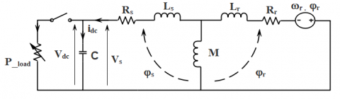
According to the described wind-power conversion structure, which consists essentially of a squirrel induction generator driven by a wind turbine as a prime mover, a variable DC load is supplied from the stator windings through a static converter with an output capacitor. Figure 1 demonstrates the corresponding per-phase conversion layout.
Figure 1. The per-phase wind-power conversion scheme base on a self-excited induction generator and a static converter association
Under the assumption that power losses relative to the converter semi-conductors switching are not considered, the active power Pload imposed by the load on the inverter DC-bus side represents the difference between the active power Ps generated at the stator and the DC-bus power Pdc [8, 14, 21]:
$P_{\text {load }}=P_{s}-P_{d c}$ (13)
If C denotes the value of the capacitor on the DC side of the static converter, then the resulting power capacitor Pdc is expressed by:
$P_{d c}=V_{d c} i_{d c}=V_{d c} C \dot{V}_{d c}$ (14)
According to Eq. (14), the corresponding Laplace's representation is:
$P_{d c}(s)=C s V_{d c}^{2}(s)$ (15)
This yields to:
$C s V_{d c}^{2}(s)=P_{s}(s)-P_{\text {load }}(s)$ (16)
According to the linear control theory, the closed control loop of the $V_{d c}^{2}$ quantity has the stator active power $P_{s}(s)$ as a control input when the power Pload is considered as a disturbance. At no-load operating conditions defined by Pload=0, the combination of Eq. (12) and Eq. (16) yields to:
$C s \frac{V_{d c}^{2}(s)}{\omega(s)}=\frac{M \varphi_{r d}}{L_{r}} \frac{1}{R_{e q}+L_{e q} s} U_{s q}(s)$ (17)
By adopting the quantity $Y(s)=\frac{V_{d c}^{2}(s)}{\omega(s)}$ as a new variable which represents the square value of the capacitor voltage and the electrical rotor speed ratio, Eq. (17) could be represented by the following compact form:
$Y(s)=\frac{K}{s\left(R_{e q}+L_{e q} s\right)} U_{s q}(s)$ (18)
with $K=\frac{M \varphi_{r d}}{C L_{r}}$.
3.1 DC-bus voltage closed-loop controller design
From Eq. (18), it is clearly seen that the new variable $Y(s)$ which is related to the output DC-bus voltage $V_{d c}$ is explicitly governed by the $U_{s q}(s)$ quantity. Figure 2 shows the corresponding closed-loop control.
Figure 2. The new variable closed-loop control
By considering the introduced output control quantity, the regulation’s error is:
$e_{Y}(s)=Y_{r e f}(s)-Y(s)$ (19)
The differentiation of Eq. (19) gives:
$s e_{Y}(s)=s Y_{r e f}(s)-s Y(s)$ (20)
The substitution of the variable $Y(s)$, which is given by Eq. (18) in Eq. (20) gives:
$s e_{Y}(s)=s Y_{r e f}(s)-\frac{K}{R_{e q}+L_{e q} s} U_{s q}^{*}(s)$ (21)
For practical considerations, where $L_{e q}$ could be neglected with respect to the $R_{e q}$ value, Eq. (18) will be reduced to:
$Y(s)=\frac{K}{R_{e q}} U_{s q}(s)$ (22)
Due to this potential simplification, Eq. (22) becomes:
$s e_{Y}(s)=s Y_{r e f}(s)-\frac{K}{R_{e q}} U_{s q}^{*}(s)$ (23)
Since the output variable $Y(s)$ which is governed by the control quantity $U_{s q}(s)$ according to a first-order transfer function defined by Eq. (18), then a simple PI controller characterized by proportional and integration actions conditioned $K_{p_{-Y}}$ and $K_{i_{-} Y}$ gains respectively will be sufficient to ensure the proposed regulation task. In this case, the error equation given by Eq. (20) will take the following dynamical form:
$s e_{Y}(s)=-K_{p_{-Y}} e_{Y}(s)-\frac{K_{i_{-} Y}}{s} e_{Y}(s)$ (24)
The multiplication of the two sides of Eq. (24) by the Laplace operator s gives:
$s^{2} e_{Y}(s)=-K_{p_{-Y}} s e_{Y}(s)-K_{i_{-} Y} e_{Y}(s)$ (25)
Eq. (25) could be rearranged in the following form:
$s^{2} e_{Y}(s)+K_{p_{-Y}} s e_{Y}(s)+K_{i_{-} Y} e_{Y}(s)=0$ (26)
Finally, Eq. (26) is factorized as:
$e_{Y}(s)\left(s^{2}+K_{p_{-Y}} s+K_{i_{-} Y}\right)=0$ (27)
The PI parameters gains $K_{p_{-Y}}$ and $K_{i_{-} Y}$ could be easily determined using the conventional pole placement technique.
Finally, the control reference quantity $U_{S q}^{*}$ that is performed by the $Y(s)$ controller is computed according to Eq. (23) as:
$\begin{array}{c}
U_{s q}^{*}(s) \\
=\frac{R_{e q}}{K}\left[\dot{Y}_{r e f}(s)+K_{p_{-Y}} e_{Y}(s)+\frac{K_{i_{-} Y}}{s} e_{Y}(s)\right]
\end{array}$ (28)
Figure 3 describes the internal controller structure relative to the Eq. (28).
Finally, Eq. (8) shows that the stator voltage component $v_{s q}^{*}$ could be obtained from the controller output quantity $U_{s q}^{*}$ as:
$v_{s q}^{*}(k)=U_{s q}^{*}(k)-\frac{L_{s}}{M} \varphi_{r d} \omega(k)$ (29)
Figure 3. DC-bus voltage regulation scheme relative to the introduced variable
3.2 Quadrature stator current component estimator model
For the proposed induction generator control scheme, the stator current component $i_{s q}$ is needed to determine the instantaneous rotor flux angular speed according to Eq. (4). Generally, a physical sensor current performs the acquisition of this current component. However, the use of this additional measuring device could be avoided by performing a dynamical estimator formulation where the $i_{s q}$ component is directly estimated from the control quantity $U_{s q}$. So, the corresponding estimation procedure could be easily synthesized according to Eq. (9) in the following way:
$\frac{d \hat{i}_{s q}}{d t}=\frac{1}{L_{e q}}\left(U_{s q}-R_{e q} \hat{i}_{s q}\right)$ (30)
The corresponding recursive derivation of Eq. (30) is computed at each instant k by:
$\begin{array}{c}
\hat{i}_{s q}(k+1) \\
=\hat{i}_{s q}(k)+\frac{T_{s}}{L_{e q}}\left(U_{s q}^{*}(k)-R_{e q} \hat{i}_{s q}(k)\right)
\end{array}$ (31)
where Ts denotes the used sampling time step value.
The described procedure relative to the proposed induction generator control is verified firstly by simulation using Matlab-Simulink software concerning a laboratory induction machine with four poles, 1.5k W, 380 V, 50 Hz (Table 1).
Table 1. Induction generator parameters Values
|
Parameter description |
Values |
|
Rated power Prated [kW] Rated voltage Urated [V] Rated frequency f [Hz] pole-pairs numbers Stator resistance Rs [Ω] Stator inductance Ls [H] Rotor resistance Rr [Ω] Rotor inductance Lr [H] Mutual inductance Lm [H] Capacitor value C [μF] |
1.5 380 50 2 4.700 0.395 0.500 0.023 0.089 2200 |
The terminal DC-bus voltage control task has been achieved via the introduced output-variable $Y(s)$ regulation using the controller structure developed in section 3.1. The corresponding closed-loop control illustrated in Figure 2 considers the simultaneous step changing in $Y_{\text {ref }}(s)$ profile and sudden load application on the DC converter side. The induction generator used in this power conversion process is entrained with an auxiliary prime mover and working at a fixed rotor flux magnitude according to the proposed vector control strategy.
To verify experimentally the proposed control idea feasibility, a practical test-bench based on a signal processor control Dspace-DS1104 board has been realized. The three-phase stator windings terminals are connected to the output capacitor through a three-phase voltage source Semikron inverter where the PWM duty-cycles are computed by the Dspace board. For performing the introduced variable Y computation, A LV 100−500 voltage sensor and an incremental encoder of 1024 pulses per revolution are used to measure the DC-bus voltage and the rotor velocity respectively. The corresponding sampling time required for these signals acquisition is chosen equal to 0.1 ms .
The basic power conversion control structure and the corresponding experimental setup test bench are shown in Figure 4 and Figure 5 respectively.
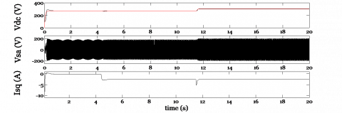
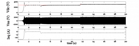
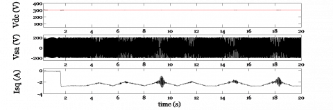
For objectivity considerations, both simulation and experimental results relative to the proposed DC-bus voltage regulation approach were performed under the same conditions. The transient response of a sudden load power application $P_{\text {load }}=800 \mathrm{~W}$ at $t=4 s$ followed up by a step-change in the controlled variable Y set value that corresponds to a similar step-changing in the DC-bus voltage from 250V to 300V introduced at $t=12 s$ are presented in Figure 6a (simulation results) and Figure 6b (experimental results). The proposed control method based on the sizing controller procedure allows a perfect rejection of the considered load-power application and rapid DC-bus voltage response performances.
Figure 4. The proposed DC-bus voltage regulation structure via the introduced variable Y control
Figure 5. The experimental test bench details
(a) Simulation results
(b) Experiment results
Figure 6. Performances of IG control employing the implemented control model
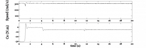
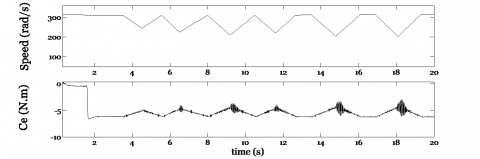
(a) Simulation results
(b) Experiment results
Figure 7. IG control responses under a variable rotor speed profile
To reproduce the practical situation where the generator shaft is entrained by a wind turbine, a variable speed profile of the DC motor is considered. Consequently, Figure 7a and Figure 7b demonstrate that the tracking performances of the proposed IG system control remain insensitive to the imposed rotor speed fluctuations.
In this work, an efficient control algorithm exclusively adapted for an isolated induction generator working under the vector control conditions is presented. According to the changing variable intentionally introduced, the resulting control approach allows hight tracking DC-bus voltage performances using only one controller. Simulation results confirmed by experiment validation tests show the proposed control technique utility for practical working situations of wind power conversion plants. The proposed system conversion control could be easily extended for large wind power generation scales.
|
B |
Viscous coefficient of friction [Nm/rad/s] |
|
C |
Capacitance [μF] |
|
$C_{e m}$ |
Electromagnetic torque [Nm] |
|
$\bar{I}_{S}$ |
stator current space vector [A] |
|
$\bar{I}_{r}$ |
rotor current space vector [A] |
|
$i_{r d}, i_{r q}$ |
d-q rotor currents components [A] |
|
$i_{s d}, i_{s q}$ |
d-q stator currents components [A] |
|
$\hat{i}_{s q}$ |
q stator current component estimated value [A] |
|
$K_{p_{-Y}}, K_{i_{-Y} }$ |
PI controller parameters gains |
|
$L_{r}$ |
rotor inductance [H] |
|
$L_{s}$ |
stator inductance [H] |
|
M |
mutual inductance [H] |
|
p |
number of pole pairs |
|
$P_{d c}$ |
DC-bus active power [W] |
|
$P_{\text {load }}$ |
Load active power [W] |
|
$P_{s}$ |
Stator power [W] |
|
$R_{r}$ |
rotor resistance [Ω] |
|
$R_{s}$ |
stator resistance [Ω] |
|
$T_{r}$ |
Rotor time constant [s] |
|
$T_{s}$ |
sampling time [s] |
|
$V_{d c}$ |
DC bus voltage [V] |
|
$\bar{V}_{r}$ |
rotor voltage space vector [V] |
|
$v_{r d}, v_{r q}$ |
d-q rotor voltages components [V] |
|
$\bar{V}_{s}$ |
stator voltage space vector [V] |
|
$v_{s d}, v_{s q}$ |
d–q stator voltages components [V] |
|
σ |
total leakage coefficient |
|
$\theta_{s}$ |
Stator pulsation [rad] |
|
$\varphi_{r d}, \varphi_{r q}$ |
d-q rotor flux components [wb] |
|
$\Omega$ |
mechanical speed [rad/s] |
|
$\omega$ |
Angular rotor speed [rad/s] |
|
$\omega_{a}$ |
Arbitrary Angular speed [rad/s] |
|
$\omega_{S}$ |
Stator pulsation [rad/s] |
[1] Singh, G.K. (2017). Self-excited induction generator for renewable applications. Encyclopedia of Sustainable Technologies, 239-256. https://doi.org/10.1016/B978-0-12-409548-9.10132-0
[2] Charafeddine, K., Sangov, K., Tsyruk, S. (2017). Automatic voltage regulation and stability analysis of three-phase self-excited induction generator for wind energy. 2017 2nd International Conference on the Applications of Information Technology in Developing Renewable Energy Processes & Systems (IT-DREPS), Amman, Jordan, pp. 1-6. https://doi.org/10.1109/IT-DREPS.2017.8277824
[3] Mishra, J., Pattnaik, M., Samanta, S. (2015). Performance evaluation of a self-excited induction generator for stand-alone wind energy conversion system. 2015 IEEE Power, Communication and Information Technology Conference (PCITC), Bhubaneswar, India, pp. 302-306. https://doi.org/10.1109/PCITC.2015.7438180
[4] Louze, L., Khezzar, A., Boucherma, M. (2006). An analytical analysis for self-excited induction generator. International Conference on Electrical Machines, ICEM2006.
[5] Ojo, O., Omozusi, O., Jimoh, A.A. (2000). The operation of an inverter-assisted single-phase induction generator. IEEE Transactions on Industrial Electronics, 47(3): 632-640. https://doi.org/10.1109/41.847904
[6] Lopes, L.A., Almeida, R.G. (2006). Wind-driven self-excited induction generator with voltage and frequency regulated by a reduced-rating voltage source inverter. IEEE Transactions on Energy Conversion, 21(2): 297-304. https://doi.org/10.1109/TEC.2006.874244
[7] Chatterjee, J.K., Perumal, B.V., Gopu, N.R. (2007). Analysis of operation of a self-excited induction generator with generalized impedance controller. IEEE Transactions on Energy Conversion, 22(2): 307-315. https://doi.org/10.1109/TEC.2006.875432
[8] Abdessemad, O., Nemmour, A. L., Louze, L., Khezzar, A. (2019). An experiment validation of an efficient vector control strategy for an isolated induction generator as wind power conversion. 2019 International Conference on Advanced Electrical Engineering (ICAEE), Algiers, Algeria, pp. 1-5. https://doi.org/10.1109/ICAEE47123.2019.9014784
[9] Mahato, S.N., Singh, S.P., Sharma, M.P. (2010). Direct vector control of stand-alone self-excited induction generator. 2010 Joint International Conference on Power Electronics, Drives and Energy Systems & 2010 Power, India, pp. 1-6. https://doi.org/10.1109/PEDES.2010.5712398
[10] Hazra, S., Sensarma, P.S. (2010). Self-excitation and control of an induction generator in a stand-alone wind energy conversion system. IET Renewable Power Generation, 4(4): 383-393. https://doi.org/10.1049/iet-rpg.2008.0102
[11] Seyoum, D., Rahman, M.F. (2002). The dynamic characteristics of an isolated self-excited induction generator driven by a wind turbine. Conference Record of the 2002 IEEE Industry Applications Conference, 2: 731-738. https://doi.org/10.1109/IAS.2002.1042641
[12] Ahmed, T., Nishida, K., Nakaoka, M. (2005). Advanced voltage control of induction generator using rotor field-oriented control. Fourtieth IAS Annual Meeting. Conference Record of the 2005 Industry Applications Conference, 4: 2835-2842. https://doi.org/10.1109/IAS.2005.1518862
[13] Seyoum, D., Rahman, M.F., Grantham, C. (2003). Terminal voltage control of a wind turbine driven isolated induction generator using stator oriented field control. Eighteenth Annual IEEE Applied Power Electronics Conference and Exposition, 2: 846-852. IEEE. https://doi.org/10.1109/APEC.2003.1179315
[14] Nemmour, A.L., Louze, L., Khezzar, A., Boucherma, M. (2007). Terminal voltage control of variable speed induction generator driven by a wind turbine supplying a DC load. 2007 International Aegean Conference on Electrical Machines and Power Electronics, Bodrum, Turkey, pp. 393-397. https://doi.org/10.1109/ACEMP.2007.4510534
[15] Kumar, S.S., Kumaresan, N., Subbiah, M., Rageeru, M. (2014). Modelling, analysis and control of stand-alone self-excited induction generator-pulse width modulation rectifier systems feeding constant DC voltage applications. IET Generation, Transmission & Distribution, 8(6): 1140-1155. https://doi.org/10.1049/iet-gtd.2013.0025
[16] Deraz, S.A., Kader, F.A. (2013). A new control strategy for a stand-alone self-excited induction generator driven by a variable speed wind turbine. Renewable Energy, 51: 263-273. https://doi.org/10.1016/j.renene.2012.09.010
[17] Louze, L., Abdessemad, O., Nemmour, A.L., Khezzar, A. (2020). An effective control of an isolated induction generator supplying DC load for wind power converting applications. Electrical Engineering and Electromechanics, (3): 65-69. https://doi.org/10.20998/2074-272X.2020.3.10
[18] Hua, Z., Wan, S., Zhou, J. (2018). A novel sensorless vector control strategy of stand-alone induction generator considering residual magnetism. 2018 21st International Conference on Electrical Machines and Systems (ICEMS), Jeju, pp. 1094-1098. https://doi.org/10.23919/ICEMS.2018.8549414
[19] Margato, E., Faria, J., Resende, M.J., Palma, J. (2011). A new control strategy with saturation effect compensation for an autonomous induction generator driven by wide speed range turbines. Energy Conversion and Management, 52(5): 2142-2152. https://doi.org/10.1016/j.enconman.2010.12.012
[20] Idjdarene, K., Rekioua, D., Rekioua, T., Tounzi, A. (2008). Vector control of autonomous induction generator taking saturation effect into account. Energy Conversion and Management, 49(10): 2609-2617. https://doi.org/10.1016/j.enconman.2008.05.014
[21] Nemmour, A.L., Mehazzem, F., Khezzar, A., Hacil, M., Louze, L., Abdessemed, R. (2010). Advanced Backstepping controller for induction generator using multi-scalar machine model for wind power purposes. Renewable Energy, 35(10): 2375-2380. https://doi.org/10.1016/j.renene.2010.02.016
[22] Bozhko, S., Peresada, S., Kovbasa, S., Zhelinskyi, M. (2016). Robust indirect field oriented control of induction generator. 2016 International Conference on Electrical Systems for Aircraft, Railway, Ship Propulsion and Road Vehicles & International Transportation Electrification Conference (ESARS-ITEC), Toulouse, France, pp. 1-6. https://doi.org/10.1109/ESARS-ITEC.2016.7841421
[23] Peresada, S., Kovbasa, S., Korol, S., Pechenik, N., Zhelinskyi, N. (2016). Indirect field oriented output feedback linearized control of induction generator. 2016 2nd International Conference on Intelligent Energy and Power Systems (IEPS), Kyiv, UKraine, pp. 1-5. https://doi.org/10.1109/IEPS.2016.7521881
[24] Leonard, W. (1985). Control of Electrical Drives Springer–Verlag: Berlin Heidelberg. New York, Tokio.
[25] Vas, P. (1990). Vector control of AC machines (Vol. 22). Oxford University Press, USA.