Aouiouat A. Faiza | Sebaa Morsli* | Allaoui Tayeb
© 2020 IIETA. This article is published by IIETA and is licensed under the CC BY 4.0 license (http://creativecommons.org/licenses/by/4.0/).
OPEN ACCESS
The performance of the Active Power Filter (APF) depends on the identification strategy of the reference currents and their control. Among the control strategies proposed in the literature to identifying the reference currents, that based on Self Tuning Filter (STF) which allows extracting directly the voltage and current fundamental components in the α-β axis at high performances, without any Phase Locked Loop (PLL). The performance of STF is function of its proportional parameter. However, there is no technique existed in the literature to dimensioning the proportional parameter of the STF filter. This paper presents an improved method for identifying the reference harmonic currents to be generated by the APF, based on STF for the extraction of harmonic currents and equipped with a Fuzzy Logic Corrector (FLC) in order to improve the waveform of the electric lines currents. The FLC adjust in real time the proportional parameter of the STF filter. The proposed FLC-STF regulator allows to having an optimal extraction of the harmonic currents. The conventional hysteresis method was used for the current control technique to generate the switching sequences of the static switches of the APF voltage inverter. The obtained simulation results, performed under the MATLAB/Simulink® environment on a system feeding a non-linear load, show good performance.
active power filter, fuzzy logic controller, hysteresis control, self tuned filter
In recent years, the world has experienced a sharp increase in electrical disturbances due to the increasing use of non-linear loads. These absorb non-sinusoidal currents and therefore produce harmonic pollution current in the grid electrical causing damage to other devices; hence a custom power device should be used to mitigate this pollution harmonic [1-6]. Among the traditional solutions, the passive power filter (PPF). It eliminates current harmonics and improves reactive energy compensation, but it has many disadvantages such as the series and parallel resonance with the system impedance which can step-up the harmonic voltage and current at specified locations [7]. The active power filter (APF) that can be either a FACTS-based device is a well-developed solution to ensure reactive power compensation and harmonic mitigation [8-10].
The performance of the APF depends on the identification strategy of the reference currents and their control. Several control strategies for the extraction of reference currents have been proposed in the literature, especially the widely used p-q theory and the id-iq theory [11]. However, the performance of APF is poor under unbalanced and distorted source voltage conditions for both strategies [11].
In this paper, a control strategy based on self-tuning filter (STF) is used for extraction of the reference harmonic currents. The major advantages of the STF are cited in the paper [12].
The STF filter extracts the fundamental component directly from the load currents and the source voltages in α-β reference frame while fixing two important parameters, namely, the pulsation ω and the proportional gain K, however, no technique existed in the literature for identification of the proportional parameter [13]. For this purpose, a fuzzy regulator has been associated with the STF filter in order to adjust in real time its proportional parameter K to obtain a perfect extraction of the reference harmonic currents.
The control of the reference currents is accomplished by a hysteresis current controller. The hysteresis control is a simple implemented classical method, it ensures a satisfactory control of the current without requiring a thorough knowledge of the model of the system to be controlled [13, 14]. The purpose of this study is to adjust the K parameter of the STF filter by a FLC controller to obtain a better improvement of the quality of the electric currents in a transmission line feeding a nonlinear load.
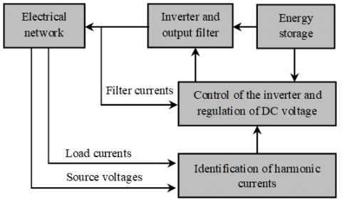
The general structure of the three-phase APF is presented in Figure 1.
Figure 1. General structure of the active power filter
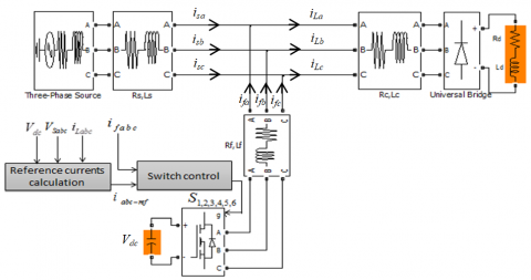
Figure 2. The system developed under MATLAB/Simulink® environment
The studied system is a transmission line composed of a three-phase source supplying a non-linear load. The parallel active filter is inserted between the power source and the non-linear load.
The nonlinear load is composed of a three full bridge rectifier supplying an inductive load RL. Figure 2 shows the system developed under Matlab/Simulink® environment.
The control strategy of the APF can be divided into two steps: The first step is the extraction of the reference currents by the STF filter equipped by the FLC controller. The second one is the control of the reference currents by the hysteresis strategy.
3.1 Harmonic currents identification
In order to have a good performance of the APF, the control strategy for the extraction of the reference current harmonics is based on the STF filter. The STF filter extracts the fundamental component directly from the load currents iLabc and the source voltages vSabc in α-β reference frame using the Concordia transformation. The current harmonics in α-β reference frame are calculated by subtracting the current fundamental components from the load currents [15].
The transformation of three-phase voltages and currents in the α-β frame is given by the following expressions:
$\left[ \begin{matrix} {{v}_{\alpha }} \\ {{v}_{\beta }} \\\end{matrix} \right]=\sqrt{\frac{2}{3}}\left[ \begin{matrix} 1 & -\frac{1}{2} & -\frac{1}{2} \\ 0 & \frac{\sqrt{3}}{2} & -\frac{\sqrt{3}}{2} \\\end{matrix} \right]\left[ \begin{matrix} {{v}_{a}} \\ {{v}_{b}} \\ {{v}_{c}} \\\end{matrix} \right]$ (1)
$\left[ \begin{matrix} {{i}_{\alpha }} \\ {{i}_{\beta }} \\\end{matrix} \right]=\sqrt{\frac{2}{3}}\left[ \begin{matrix} 1 & -\frac{1}{2} & -\frac{1}{2} \\ 0 & \frac{\sqrt{3}}{2} & -\frac{\sqrt{3}}{2} \\\end{matrix} \right]\left[ \begin{matrix} {{i}_{a}} \\ {{i}_{b}} \\ {{i}_{c}} \\\end{matrix} \right]$ (2)
The instantaneous active power p and the instantaneous reactive power q are defined by [16]:
$\left[ \begin{matrix} p \\ q \\\end{matrix} \right]=\left[ \begin{matrix} {{v}_{\alpha }} & {{v}_{\beta }} \\ -{{v}_{\beta }} & {{v}_{\alpha }} \\\end{matrix} \right]\left[ \begin{matrix} {{i}_{\alpha }} \\ {{i}_{\beta }} \\\end{matrix} \right]$ (3)
$p={{v}_{\alpha }}.{{i}_{\alpha }}+{{v}_{\beta }}.{{i}_{\beta }}$ (4)
$q={{v}_{\alpha }}.{{i}_{\beta }}-{{v}_{\beta }}.{{i}_{\alpha }}$ (5)
The instantaneous active and reactive powers can be written as follows:
$\left\{ \begin{align} & p=\bar{p}+\tilde{p} \\ & q=\bar{q}+\tilde{q} \\ \end{align} \right.$ (6)
where, $\bar{p} \text { and } \bar{q}$ denote the continuous components and $\tilde{p}$ and $\tilde{q}$ denote the harmonic components of p and q.
From Eq. (3), the expressions of the load current components in the α-β reference frame are:
$\left[ \begin{matrix} {{i}_{\alpha }} \\ {{i}_{\beta }} \\\end{matrix} \right]={{\left[ \begin{matrix} {{v}_{\alpha }} & {{v}_{\beta }} \\ -{{v}_{\beta }} & {{v}_{\alpha }} \\\end{matrix} \right]}^{-1}}\left[ \begin{matrix} p \\ q \\\end{matrix} \right]=\frac{1}{v_{\alpha }^{2}+v_{\beta }^{2}}\left[ \begin{matrix} {{v}_{\alpha }} & -{{v}_{\beta }} \\ {{v}_{\beta }} & {{v}_{\alpha }} \\\end{matrix} \right]\left[ \begin{matrix} p \\ q \\\end{matrix} \right]$ (7)
By replacing Eq. (6) in Eq. (7), the expressions of the currents in α-β reference frame are expressed by:
$\left[ \begin{matrix} {{i}_{\alpha }} \\ {{i}_{\beta }} \\\end{matrix} \right]=\frac{1}{v_{\alpha }^{2}+v_{\beta }^{2}}\left[ \begin{matrix} {{v}_{\alpha }} & -{{v}_{\beta }} \\ {{v}_{\beta }} & {{v}_{\alpha }} \\\end{matrix} \right]\left[ \begin{matrix} {\bar{p}} \\ {\bar{q}} \\\end{matrix} \right]+\frac{1}{v_{\alpha }^{2}+v_{\beta }^{2}}\left[ \begin{matrix} {{v}_{\alpha }} & -{{v}_{\beta }} \\ {{v}_{\beta }} & {{v}_{\alpha }} \\\end{matrix} \right]\left[ \begin{matrix} {\tilde{p}} \\ {\tilde{q}} \\\end{matrix} \right]$ (8)
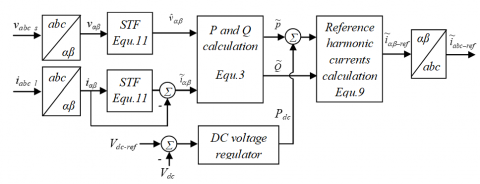
Since we are interested in the simultaneous compensation of current harmonics and reactive energy, the continuous power pc needed to maintain the DC voltage Vdc at constant value, will be added to the harmonic component $\tilde{p}$ (Figure 3).
The reference harmonic currents denoted iα-ref and iβ-ref, are expressed in the α-β reference frame by:
$\left[ \begin{matrix} {{i}_{\alpha -ref}} \\ {{i}_{\beta -ref}} \\\end{matrix} \right]=\frac{1}{v_{\alpha }^{2}+v_{\beta }^{2}}\left[ \begin{matrix} {{v}_{\alpha }} & -{{v}_{\beta }} \\ {{v}_{\beta }} & {{v}_{\alpha }} \\\end{matrix} \right]\left[ \begin{matrix} \tilde{p}+{{p}_{c}} \\ {\tilde{q}} \\\end{matrix} \right]$ (9)
Figure 3. Extraction of reference current harmonics with STF filter
The reference harmonic currents in the three phase reference frame can be determined using the inverse Concordia transformation as follows:
$\left[ \begin{matrix} {{i}_{a-ref}} \\ {{i}_{b-ref}} \\ {{i}_{c-ref}} \\\end{matrix} \right]=\sqrt{\frac{2}{3}}\left[ \begin{matrix} 1 & 0 \\ -\frac{1}{2} & \frac{\sqrt{3}}{2} \\ -\frac{1}{2} & -\frac{\sqrt{3}}{2} \\\end{matrix} \right]\left[ \begin{matrix} {{i}_{\alpha -ref}} \\ {{i}_{\beta -ref}} \\\end{matrix} \right]$ (10)
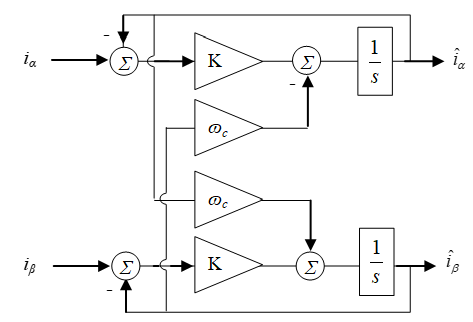
The principle of the STF consists of extracting the fundamental components $\hat{\imath}_{\alpha \beta}$ at the pulsation ωc of the currents iab, the harmonic components are calculated by subtracting the STF outputs from the corresponding input signals (Figure 4).
Figure 4. Self-tuning filter
The authors [13] presented the expressions of the fundamental components $\hat{X}_{\alpha \beta}$ according to the real quantities Xab , (X can be a current or a voltage):
$\begin{align} & {{{\hat{X}}}_{\alpha }}(s)=\frac{K}{s}\left( {{X}_{\alpha }}(s)-{{{\hat{X}}}_{\alpha }}(s) \right)-\frac{{{\omega }_{c}}}{s}{{{\hat{X}}}_{\beta }}(s) \\ & {{{\hat{X}}}_{\beta }}(s)=\frac{K}{s}\left( {{X}_{\beta }}(s)-{{{\hat{X}}}_{\beta }}(s) \right)+\frac{{{\omega }_{c}}}{s}{{{\hat{X}}}_{\alpha }}(s) \\\end{align}$ (11)
In this system of equations the K parameter plays an important role for the extraction of the fundamental quantities $\hat{X}_{\alpha \beta}$, however there is no method which allows its dimensioning. Indeed, a value too low or too important of K does not allow the filter to effectively eliminate all the harmonics. In this study, a fuzzy controller was associated with the STF filter to adjust the value of the K parameter based on the operating point of the system. The new FLC-STF filter thus obtained makes it possible to extract the fundamental quantities efficiently and independently of the initial value given to the K parameter.
3.2 Fuzzy logic controller
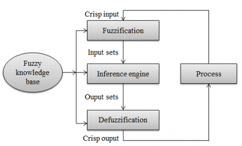
This type of controller does not require any knowledge of the mathematical model of the system. It is composed of four main blocks (Figure 5): the knowledge base, the inference system, the fuzzification interface and the defuzzification interface [17-20].
Figure 5. Synoptic diagram of the fuzzy controller
3.2.1 FLC-STFControllerconfiguration
The purpose of the FLC-STF filter developed in this study (Figure 6) is to extract the fundamental quantities $\hat{\imath}_{\alpha \beta}$ necessary in the identification phase of the reference harmonic currents. The role of the FLC regulator is to adjust in real time the parameter K of the STF filter to extract the harmonics of currents as much as possible.
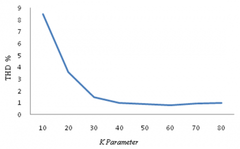
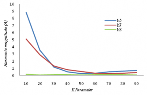
A study was conducted to determine the effect of the K parameter of the STF filter on low order current harmonics (Figure 7). This study consists to varying the K parameter and calculating, for each value of K, the amplitudes of the 3rd order harmonic (h3), the 5th order harmonic (h5) and the 7th order harmonic (h7), and the corresponding THD while exploiting the potential of the MATLAB/Simulink® software. Figure 7 and Figure 8 show, respectively, the variations of the THD and the magnitudes of some low order harmonics of current as functions of K parameter of the STF filter for a non linear load composed of a three phase full bridge rectifier with an RL connection.
Figure 6. The proposed FLC-STF scheme for active power filter
Figure 7. The variation of THD as a function of the K parameter of the STF filter for a nonlinear load
Figure 8. Curves of harmonic variations h3, h5 and h7 as a function of K parameter of the STF filter for nonlinear load
This study showed that K parameter can affect three parameters, which are: the THD, h5, and h7. The 3rd harmonic is not affected by the variations applied to K parameter.
For this purpose, the designed FLC controller has three input variables are: THD, h5 and h7, then the output variable of the FLC is the K parameter of the STF filter.
The fuzzy controller is characterized by:
The inference system consists of five rules as follows:
Figure 9. Membership functions defined for the inputs variables (a) and output variable (b) of FLC controller
3.3 Hysteresis controller
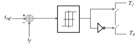
In the hysteresis current controller presented by Figure 10, the current produced by the filter if is forced to follow reference current iref within a hysteresis band by the switching action of the inverter.
The hysteresis controller is fed by the error signal, which is the difference between the reference current irefand the current produced by the filter if, this error is compared with a fixed tolerance band in order to driving the switching signals [21-23].
Figure 10. Hysteresis current controller.
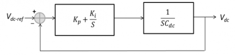
3.4 DC capacitor voltage control
The control of the DC-link capacitor voltage is necessary to improve the compensation performance of the APF. In fact, the DC-link capacitor voltage control maintains the voltage Vdc at constant value [11]. This voltage is compared with its reference Vdc-ref, and then the error voltage is applied to the input of a standard type PI corrector as shown in Figure 11. According to the error between the reference voltage and the DC capacitor voltage, the PI controller generates a signal proportional to the power absorbed or supplied by the DC link capacitor [24-26]. Then it is added to the harmonic component of active power.
Figure 11. The control loop of the DC capacitor voltage
The performance of the FLC-STF scheme for APF filter has been tested and evaluated by using SimPowerSystems toolbox in MATLAB/Simulink® software.
The APF system studded is presented in Figure 2. The circuit parameters are given in Table 2. The nonlinear load is consisting of a three-phase diode bridge rectifier with RL connection.
The following figures show the simulation results of the system illustrated in Figure 2.
Figure 12 shows the waveform of the line current absorbed by the nonlinear load consisting of three-phase rectifier with RL connection. In Figure 13, the THD spectrum is presented. It reaches a value of 22.03%.
Figure 12. A-phase load current waveform for a nonlinear load
Figure 13. Harmonic spectrum of the load current corresponds to the nonlinear load in Figure 12
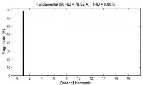
Figure 14. Phase source current obtained by the FLC-APF scheme; the initial value of K parameter was set at 60
Figure 15. Harmonic spectrum of the source current illustrated in Figure 14
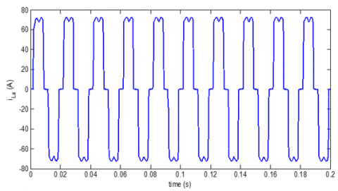
Figure 16. A-phase waveform of the filter output current ifa
Figure 17. Variation of k parameter values adapted by FLC controller for initial value of K=30
Figure 14 and Figure 15 show the waveform of the source current and its THD spectrum respectively, when the mitigation of harmonic currents is ensured by using the FLC-STF scheme for the active power filter for the same nonlinear load. The THD of the source current is computed as 0.86%.
The APF generates a harmonic current illustrated in Figure 16. This harmonic current is injected in the transmission line to ensuring the demand of the nonlinear load for harmonic current; thereby the source generates only a sinusoidal current. In Figure 17, it is presented the variation of STF proportional parameter obtained by the FLC controller when the initial value of K parameter is set at 30. It is clear that the FLC controller adjusts, in real time, its output and therefore the K parameter in order to improve the THD of the current.
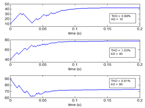
It should be noted that the THD is a function of the initial value of the K parameter. For this purpose, it is presented in Figure 18 three cases correspond to three initial values of K for the same nonlinear load. It is clear from this figure that the THD can be affected by the initial value of K. In other hand, it was observed that a very small value of K can generate a critical transient behavior characterized by a very large current peak. However, the THD obtained with FLC-STF scheme for any initial value of K is greater than that obtained with the STF filter alone.
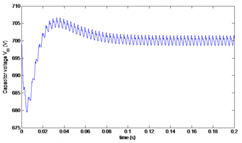
The curve of the DC link capacitor voltage is presented in Figure 19. The capacitor voltage is controlled at 700 volts with a PI type controller as shown in Figure 11. It is clear from this figure that the Dc link capacitor voltage follows the reference voltage vdc-ref efficiently.
Figure 18. Waveforms of the K parameter adjusted by the FLC controller for different initial values of K parameter
Figure 19. Waveform of capacitor voltage Vdc
Table 1. The capability of APF output harmonics
|
|
Without filter |
STF alone (K=60) |
FLC-STF |
|
|
THD |
22.03% |
1.13% |
0.86% |
|
|
Magnitude (A) |
3th order harmonic |
0.05 |
0.03 |
0.01 |
|
5th order harmonic |
15.77 |
0.83 |
0.32 |
|
|
7th order harmonic |
5.98 |
0.28 |
0.26 |
|
|
11th order harmonic |
3.0 |
0.12 |
0.08 |
|
In order to show the efficiency of the proposed scheme, it is illustrated in Table 1 the values of THD parameter and magnitudes of the 5th, 7th and 11th order harmonics for three cases; the first one corresponds to the case in which no filter is used to mitigate the harmonic currents. In the second one, the identification method for the APF filter is based on a STF alone and in the last one the identification method is based on FLC-STF scheme, in this case the initial value of the K parameter was set at 60 and the fundamental component of the current reached an amplitude of 78,52 A.
From these results, it can be seen that the control scheme proposed in this paper improves the mitigation of harmonic currents and therefore it enhances the compensation performance of the APF.
Table 2. System parameters
|
Parameters |
Values |
|
Supply voltage |
Vs = 220 V, fs = 50 HZ |
|
The source side line parameters |
Ls = 0.02 mH, Rs = 3.5 mΩ |
|
Load parameters |
Lch = 0.1 mH, Rch = 3 Ω |
|
The load side line parameters |
Lc= 0.02 mH, Rc= 3.5 mΩ |
|
The APF: Interfacing bloc |
Lf= 3 mH, Rf= 3 mΩ |
|
DC bus |
Vdc = 700 V, Cdc = 2.2 mf |
|
Hysteresis band |
H= ± 0.1 A |
The work presented in this paper has proposed an improved method for identifying reference harmonic currents based on the use of an STF filter in place of conventional filters (low pass or high pass) used in the instantaneous power theory. The STF filter was endowed with an FLC controller to adjust, in real time, its proportional parameter. The main objective was to generate the reference harmonic currents with a minimum of error to compensate the disturbances caused by the nonlinear loads. For current control, the classic hysteresis control was used. The FLC-STF scheme has allowed obtaining a perfect and efficient extraction of harmonic currents.
The simulation results demonstrated and enhanced the efficiency of using the FLC-STF scheme and the hysteresis current controller in the APF filter control.
[1] Akagi, H. (1996). New trends in active filters for power conditioning. IEEE Trans. on industry Applications, 32(6): 1312-1322. https://doi.org/10.1109/28.556633
[2] Singh, B., Al-Haddad, K., Chandra, A. (1999). A review of active power filters for power quality improvement. IEEE Trans. Ind. Electron, 46(5): 960-971. https://doi.org/10.1109/41.793345
[3] Hou, S., Fei, J. (2015). Adaptive fuzzy back stepping control of three-phase active power filter. Control Engineering Practice, 45: 12-21. https://doi.org/10.1016/j.conengprac.2015.08.005
[4] Mindykowski, J., Xu, X.Y., Tarasiuk, T., Yang, C. (2015). An improved algorithm of compensating current generation for active power filters control. Measurement, 63: 187-194. https://doi.org/10.1016/j.measurement.2014.12.012
[5] Saidi, S., Abbassi, R., Chebbi, S. (2015). Fuzzy logic controller for three-level shunt active filter compensating harmonics and reactive power. International Journal of Adaptive Control and Signal Processing, 30(6): 809-823. https://doi.org/10.1002/acs.2637
[6] Kim, S., Enjeti, P.N. (2002). A new hybrid active power filter (APF) topology. IEEE Transactions on Power Electronics, 17(1): 48-54. https://doi.org/10.1109/63.988669
[7] Sharaf, A.M., Wang, W., Ismail, H.A. (2008). A novel hybrid active filter compensator for stabilization of wind-utility grid interface scheme. Euro. Trans. Electr. Power, 20(3): 306-326. https://doi.org/10.1002/etep.313
[8] Zellouma, L., Rabhi, B., Saad, S., Benaissa, A., Benkhoris, M.F. (2015). Fuzzy logic controller of five levels active power filter. Energy Procedia, 74: 1015-1025. https://doi.org/10.1016/j.egypro.2015.07.738
[9] Loutfi, B. (2019). Comparative analysis hysteresis and fuzzy logic hysteresis controller of shunt active filter. Advances in Modelling and Analysis B, 62(2-4): 37-42. https://doi.org/10.18280/ama_b.622-401
[10] Marcos, B.K., Cursino, B.J., Antonio, M.N.L. (2018). Shaping control strategies for active power filters. IET Power Electronics, 11(1): 175-181. https://doi.org/10.1049/iet-pel.2016.0863
[11] Patel, R., Panda, A.K. (2014). Real time implementation of PI and fuzzy logic controller based 3-phase 4-wire interleaved buck active power filter for mitigation of harmonics with id-iq control strategy. International Journal of Electrical Power and Energy Systems, 59: 66-78. https://doi.org/10.1016/j.ijepes.2014.01.021
[12] Abdusalam, M., Poure, P., Karimi, S., Saadate, S. (2009). New digital reference current generation for shunt active power filter under distorted voltage conditions. Electric Power Systems Research, 79(5): 759-765. https://doi.org/10.1016/j.epsr.2008.10.009
[13] Abdusalam, M., Poure, P., Saadate, S. (2008). Hardware implementation of a three-phase active filter system with harmonic isolation based on self-tuning-filter. IEEE 39th Annual Conference on Power Electronics Specialists, pp. 2875-2881. https://doi.org/10.1109/PESC.2008.4592385
[14] Albanna, A., Hatziadoniu, C.J. (2009). Harmonic analysis of hysteresis controlled grid connected inverters. IEEE/PES Power Systems Conference and Exposition, pp. 1-8. https://doi.org/10.1109/PSCE.2009.4840085
[15] Benyettou, L., Tebbakh, M. (2018). Shunt active filter using fuzzy logic based on three-level (NPC) inverter to compensate current harmonics. Advances in Modelling and Analysis B, 61(4): 198-206. https://doi.org/10.18280/ama_b.610404
[16] Pierfederici, S., Martin, J.P., Meibody-Tabar, F., Davat, B. (2003). Fixed frequency AC current mode controller for a three phase voltage source inverter. IEEE 34th Annual Conference on Power Electronics Specialists, pp. 490-494. https://doi.org/10.1109/PESC.2003.1218104
[17] Saidi, S., Abbassi, R., Chebbi, S. (2016). Fuzzy logic controller for three-level shunt active filter compensation harmonics and reactive power. International Journal of Adaptive Control and Signal Processing, 30(6): 809-823. https://doi.org/10.1002/acs.2637
[18] Saad, L., Zellouma, L. (2009). Fuzzy logic controller for three-level shunt active filter compensation harmonics and reactive power. Electric Power Systems Research, 79(10): 1337-1341. https://doi.org/10.1016/j.epsr.2009.04.003
[19] Belaidi, R., Haddouche, A., Guendouz, H. (2012). Fuzzy logic controller based three-phase shunt active power filter for compensating harmonics and reactive power under unbalanced mains voltages. Energy Procedia, 18: 560-570. https://doi.org/10.1016/j.egypro.2012.05.068
[20] Arora, N., Saini, J.R. (2016). Estimation and approximation using neuro-fuzzy systems. International Journal of Intelligent Systems and Applications, 8(6): 9-18. https://doi.org/10.5815/ijisa.2016.06.02
[21] Jog, A.N., Apte, N.G. (2007). An adaptive hysteresis band current controlled shunt active power filter. 2007 Compatibility in Power Electronics, pp. 1-5. https://doi.org/10.1109/CPE.2007.4296515
[22] Buso, S., Fasolo S., Malesani L., Mattavelli P. (2000). A dead-beat adaptive hysteresis current control. IEEE Transactions on Industry Applications, 36(4): 1174-1180. https://doi.org/10.1109/28.855976
[23] Kale, M., Ozdemir, E. (2005). An adaptive hysteresis band current controller for shunt active power filter. Electric Power Systems Research, 73(2): 113-119. https://doi.org/10.1016/j.epsr.2004.06.006
[24] Zhou, Z., Liu, Y. (2012). Pre-sampled data based prediction control for active power filter. International Journal of Electrical Power & Energy Systems, 37(1): 13-22. https://doi.org/10.1016/j.ijepes.2011.10.029
[25] Liu, D.D., Zhou, L., Sai, X.Y. (2020). Vector-proportional-integral control of inductor-capacitor-inductor active power filter under the alpha-beta stationary coordinate system. European Journal of Electrical Engineering, 22(1): 79-86. https://doi.org/10.18280/ejee.220110
[26] Ismail, G., Toufik, B.M., Barkat, S.A.I.D. (2018). Real time implementation of feedback linearization control based three phase shunt active power filter. European Journal of Electrical Engineering, 20(4): 517-532. https://doi.org/10.3166/EJEE.20.517-532