Yahia Moati* | Katia Kouzi
© 2020 IIETA. This article is published by IIETA and is licensed under the CC BY 4.0 license (http://creativecommons.org/licenses/by/4.0/).
OPEN ACCESS
As know, Direct Torque Control (DTC) suffers from the high ripples of the torque and flux, caused by the variable switching frequency. Torque ripple in DTC drives can be reduced if an Indirect Three-Level Matrix Converter (ITLMC) is employed instead of a conventional Two-Level Indirect Matrix Converter. Nevertheless, this problem can be still large if low switching frequencies are used. In order to overcome this problem, a Constant Switching Frequency controller (CSFC) is proposed to replace the five-level hysteresis torque comparator for reducing the ripples and improving the flux regulation in low and zero speed operation. Furthermore, the control scheme performance is enhanced by inserting a robust Synergetic Controller (SC) in the outer loop for speed regulation. Simulation results with a comparative analysis have indicated the special merit of the proposed scheme, which makes it competitive with the existing control strategies.
Dual Stator Induction Motor (DSIM), Indirect Three-Level Matrix Converter (ITLMC), Space Vector Modulation (SVM), Constanat Switching Frequency Controller (CSFC), Direct Torque Control (DTC), Synergetic Control (SC)
In high power applications, the multiphase machine has mostly replaced the conventional three-phase one, this mainly owes to the enhancement of power converters, which can create multiphase systems of voltages and currents. Furthermore, the multiphase machine has various points of interest such as a higher torque density, reduced harmonic content in the DC link current, split power among phases and the fact that it permits working with one or several phases in a defective motor [1, 2].
One of the widely recognized multiphase machines is the Dual-Stator Induction Machine (DSIM), it has two windings with 30 electrical degrees displacement between phases, which are generally powered by a six-phase inverter or two parallel three-phase inverters. Problems of modeling, analysis, and control of such machines are studied by Barrero et al. [3, 4] Several advanced control strategies comprising the well-known DTC, Field-Oriented Control (FOC), Model Predictive Control (MPC), etc., have been applied to the DSIM. Recent research improvements in the control of DSIM and comparison of some control strategies have been reviewed in the papers [5, 6].
Among the many powerful techniques used for the control of the DSIM is the DTC technique that was proposed by Takahashi and Noguchi [7], this technique is distinguished the fast dynamics, simple structure, simple decoupled scheme between the electromagnetic torque control and stator flux, and its robustness. In the other hand, it has some well-known drawbacks such as the weak stator flux regulation especially at low and zero speed operation referred to as the flux droop, high ripples of torque, flux, and variable switching frequency [8]. The main reason for these drawbacks to the use of the hysteresis controller. With this impact, researchers are trying to enhance the execution of DTC, in this context, DTC has been used with Space Vector Modulation (DTC-SVM) [9], it is based on the synthesis of voltage vectors in each sampling time by the space vector modulation, therefore, the two-hysteresis comparators and the switching table are omitted. This technique experienced some improvements in the performances of the DTC; however, it is characterized by a high computational time, complexity of structure, and it cannot fulfill the stability at a zero-speed operation. Model Predictive Control (MPC-DTC) [10], uses a model to predict the future state, the controller can then decide the adequate control to optimize some given cost function in some finite time-horizon. This technique is distinguished by the reduction of torque ripple, enhancement of dynamic performance, on the other hand, the control complexity is multiplied, parameter dependencies are inescapably increased and high computation is required compared with conventional DTC. Artificial Intelligence (AI) techniques such as Artificial Neural Networks (ANN) and Fuzzy Logic (FL) have been studied in many types of research [11] However, they usually require powerful micro-controllers in order to rapidly execute their control algorithms. All these techniques affect the robustness and the simplicity of the classical DTC.
Recently, a constant switching frequency torque controller (CSFC-DTC) was initially proposed by Idris and Yatim [12]. It is based on a Proportional-Integral (PI) controller and two triangular carrier signals out of phase to replace the hysteresis torque controller. Compared with the classical (DTC), the (CSFC-DTC) ensures diverse advantages such as the reduction of torque ripples, constant switching frequency operation, a robust stability thanks to the acceptable flux regulation in all speed ranges especially in low and zero speed, furthermore, it keeps the simple structure of control with almost no changes in the basic structure of DTC. Previous studies of (CSFC) used 2-level classical inverter [13]. However, CSFC was never applied to the matrix converter.
The Matrix Converter (MC), which allows a direct AC-to-AC conversion without any use of bulky energy storage elements in the intermediate link, gained a great interest in the few last years. This owes to its distinguishable advantages such as the input and output sinusoidal current, generation of voltage waveforms with variable magnitude and frequency, the controllable input power factor, its compact topology free of the dc-link capacitor, bidirectional power flow and low distortion of the input current [14, 15]. The first research studies on the MC amount to the work of Venturini [16]. In the late 1980s and early 1990s, Space Vector Modulation (SVM) and Indirect Space Vector Modulation (ISVM) schemes were likewise presented by a few types of research [17]. A review of MCs is given by Wheeler et al. [14], and the modulation strategies are reviewed in the paper [15]. “Casadei” firstly exhibited the use of MC in the DTC [18]. In his work, it is shown that the MC offers an extra degree of freedom, which is beneficial for the control of the Input Power Factor (IPF) in addition to reducing the ripples of the flux and torque. This strategy has been stretched out to the IMC [19]. The aim was to attain several goals, such as the enhancement of dynamics, reduction of the torque and flux ripples, improvement of estimation of variables such as the flux and torque and overcoming some drawbacks of DTC for the MC. The first application of DTC on a MC powering a DSIM can be found by Talaeizadeh et al. [20].
Moreover, the DTC strategy can be enhanced by inserting robust controllers to improve the stability and robustness of the entire control scheme. Various nonlinear control techniques have been proposed to enhance control performances such as rejection capabilities, good support for the external load disturbance and fast dynamic response.
The Sliding Mode Control (SMC) method shows good dynamics in transient and steady state and excellent robustness properties. However, SMC suffers from the chattering phenomenon. To eliminate the later and in order to increase the SMC capabilities, Higher-Order Sliding Mode (HOSM) techniques were proposed by Levant [21]. However, HOSM shows some design difficulties. Recently, a new technique appeared known as Synergetic Control (SC) [22], it is characterized by its simplicity of design, external disturbance rejection capabilities, and the global stability assurance of the system.
This paper introduces a Synergetic Control design for the external speed regulation loop in order to enhance the performances of the control scheme. The purpose is to implement a controller for the DSIM based on CSFC-DTC powered by an ITLMC. This results in a robust controller that has combined advantages given by the CSFC-DTC and ITLMC, such as the minimization of flux and torque ripples while ensuring a power factor equal to unity. In addition, a robust synergetic speed controller (SSC) is introduced to comprehensively improve the performances of the speed control and ensure the rejection of the load disturbances. The major benefit of the proposed method is its simplicity of design and implementation of its algorithm while keeping the structure of the conventional DTC.
The remainder of this paper is organized as follows: Sec. 2. presents a brief review on synergetic control, summarizes the DTC principle for the DSIM and for the DSIM powered by ITLMC. Sec. 3. gives the mathematical model of DSIM and the ITLMC. Sec. 4. details the proposed controller and the concept of the proposed CSFC. Sec. 5. is dedicated to a simulation study, which illustrates the robust performance of the proposed scheme. Finally, conclusions and perspectives are given in section 6.
2.1 Direct torque control of DSIM
The DTC depends on the stator flux orientation. The latter can be communicated in a referential identified with the stator of the machine by condition (1), below [20-28]:
$\phi_{S 1,2}=\int_{0}^{t}\left(V_{S 1,2}-R_{S 1,2} I_{S 1,2}\right) d t+\phi_{S 1,2}(0)$ (1)
For the situation where a non-zero voltage vector is connected amid an interim $\left[0, T_{e}\right]$, the voltage drop can be neglected $\left(R_{S 1,2} I_{S 1,2}\right)$ with respect to VS. Hence, Eq. (1). is given by:
$\phi_{S 1,2}(t)=V_{S 1,2} T_{e}+\phi_{S 1,2}(0)$ (2)
The flux vector moves with the value of $V_{S 1,2} T_{e}$ so the flux vector can be fixed by the application of a suitable voltage vector.
2.2 Torque and stator flux estimation
The stator flux amplitude and its phase are estimated by the following two-phase components linked to the stator as:
$\left\{\begin{array}{l}\phi_{S_{\alpha 1,2}}=\int_{0}^{t}\left(V_{S_{\alpha 1,2}}-R_{S 1,2} I_{S_{\alpha 1,2}}\right) d t \\ \phi_{\beta_{\alpha_{1,2}}}=\int_{0}^{t}\left(V_{S_{\beta 1,2}}-R_{S 1,2} I_{S_{\beta 1,2}}\right) d t\end{array}\right.$ (3)
The magnitude of stator flux and its phase are given by:
$\left|\phi_{S 1,2}\right|=\sqrt{\phi_{S_{\alpha 1,2}}^{2}+\phi_{\beta_{\alpha 1,2}}^{2}}$ (4)
$\theta_{\phi_{S 1,2}}=\operatorname{artcg}\left(\frac{\phi_{S_{\beta 1,2}}}{\phi_{S_{\alpha 1,2}}}\right)$ (5)
Consequently, the estimation of the flux depends only on the stator resistance as a parameter. The voltage and the current are measurable quantities. The electromagnetic torque can be estimated from the estimation of the stator flux and the measurement of the stator current.
$T_{e}=P\left(\phi_{S_{\alpha 1,2}} I_{S_{\beta 1,2}}-\phi_{S_{\beta 1,2}} I_{S_{\alpha 1,2}}\right)$ (6)
The following Figure 1 shows the classical DTC of DSIM.
Figure 1. DTC of DSIG
2.3 Direct torque control of ITLMC
The DTC powered by ITLMC structure is similar to the conventional DTC powered by indirect matrix converter, this method proposed for the first time by Li and Liu [24]. So the rectifier stage is controlled by a current with SVM, in order to keep the input power at unity, and maximize its output voltage [25]. The inverter stage is controlled by the switching table DTC of three levels (reported in table II) for the regulation of the torque and flux.
2.3.1 Rectifier control design
The aim is to obtain the maximum value of the virtual Vdc by controlling the power factor of the input bus voltage, based on SVM, the reference vector can be synthesized with the adjacent vectors $I_{\gamma}, I_{\delta}$ and a null vector I0 [25, 26].
$I_{i n}=d_{\gamma} I_{\gamma}+d_{\delta} I_{\delta}$ (7)
This is illustrated in Figure 2.
Figure 2. Input current modulation for rectification stage
The duty cycles of each sector are defined in
$\left\{\begin{array}{c}d_{\gamma}=m_{c} \sin \left(\theta_{i n}\right) \\ d_{\delta}=m_{c} \sin \left(\frac{\pi}{3}-\theta_{i n}\right) \\ d_{0}=1-d_{\gamma}-d_{\delta}\end{array}\right.$ (8)
where, $m_{c}=\frac{\left|I_{i n}\right|}{I_{r e c}}$ and $0<\theta_{i n}<\frac{\pi}{3}$.
The null vector I0 is eliminated in order to maximize the voltage Vdc. The two cyclic ratios are normalized according to the following Eq. (9):
$\left\{\begin{array}{c}d_{\gamma}^{\prime}=\frac{d_{\gamma}}{d_{\gamma}+d_{\delta}}=\frac{\sin \left(\theta_{i n}\right)}{\cos \left(\frac{\pi}{6}-\theta_{i n}\right)} \\ d_{\delta}^{\prime}=\frac{d_{\delta}}{d_{\delta}+d_{\gamma}}=\frac{\sin \left(\frac{\pi}{3}-\theta_{i n}\right)}{\cos \left(\frac{\pi}{6}-\theta_{i n}\right)} \\ d_{0}=0 \text { and } d_{\gamma}+d_{\delta}=1\end{array}\right.$ (9)
To guarantee the continuity of the current in the rectifier, the following condition must be respected.
$S_{a p}+S_{b p}+S_{c p}=1$ (10)
From the relation (10), one can recapitulate the nine valid switching combinations in Table 1 below. These Combinations can be used for the rectifier (Figure 2).
Table 1. Switching table of rectifier
|
Vectors |
States |
$\mathrm{I}_{\mathrm{a}}$ |
$\mathrm{I}_{\mathrm{b}}$ |
$\mathrm{I}_{\mathrm{c}}$ |
$\left|I_{E}\right|$ |
$\theta_{i n}$ |
$U_{\text {rec}}$ |
|
|
Active |
$I_{1}$ |
$\left[\begin{array}{c}100 \\ 010\end{array}\right]$ |
$I_{\text {rec}}$ |
$-I_{\text {rec}}$ |
0 |
$\frac{2}{\sqrt{3}} I_{r e c}$ |
$-\frac{\pi}{6}$ |
$U_{a b}$ |
|
$I_{2}$ |
$\left[\begin{array}{c}100 \\ 001\end{array}\right]$ |
$I_{\text {rec}}$ |
0 |
$-I_{\text {rec}}$ |
$\frac{2}{\sqrt{3}} I_{r e c}$ |
$\frac{\pi}{6}$ |
$U_{a c}$ |
|
|
$I_{3}$ |
$\left[\begin{array}{c}010 \\ 001\end{array}\right]$ |
0 |
$I_{\text {rec}}$ |
$-I_{\text {rec}}$ |
$\frac{2}{\sqrt{3}} I_{r e c}$ |
$\frac{\pi}{2}$ |
$U_{ bc}$ |
|
|
$I_{4}$ |
$\left[\begin{array}{c}010 \\ 100\end{array}\right]$ |
$-I_{\text {rec}}$ |
$I_{\text {rec}}$ |
0 |
$\frac{2}{\sqrt{3}} I_{r e c}$ |
$\frac{5 \pi}{6}$ |
$U_{ ba}$ |
|
|
$I_{5}$ |
$\left[\begin{array}{c}001 \\ 100\end{array}\right]$ |
$-I_{\text {rec}}$ |
0 |
$I_{\text {rec}}$ |
$\frac{2}{\sqrt{3}} I_{r e c}$ |
$-\frac{5 \pi}{6}$ |
$U_{ ca}$ |
|
|
$I_{6}$ |
$\left[\begin{array}{c}001 \\ 010\end{array}\right]$ |
0 |
$-I_{\text {rec}}$ |
$I_{\text {rec}}$ |
$\frac{2}{\sqrt{3}} I_{r e c}$ |
$-\frac{\pi}{2}$ |
$U_{ cb}$ |
|
|
Zero |
$I_{0}$ |
$\left[\begin{array}{c}100 \\ 100\end{array}\right]$ |
0 |
0 |
0 |
0 |
0 |
0 |
|
$\left[\begin{array}{c}010 \\ 010\end{array}\right]$ |
0 |
0 |
0 |
0 |
0 |
0 |
||
|
$\left[\begin{array}{c}001 \\ 001\end{array}\right]$ |
0 |
0 |
0 |
0 |
0 |
0 |
||
2.3.2 Inverter control
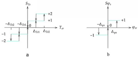
The inverter stage, which is a three-level NPC structure, is controlled with three-level DTC. This technique has the same principle as the conventional DTC but gives a greater number of vectors offered by the inverter three levels by subdivision the space of the flux vector a 12 sector, in order to benefits of this feature, one uses multilevel hysteresis comparators:
- For flux regulation, one uses three levels hysteresis;
- For torque control, one uses a hysteresis with five levels as shown in Figure 3.
Figure 3. Hysteresis control: a) torque, b) flux
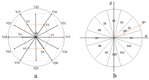
In fact, the three-level inverter offers 27 vectors that can be classified into 4 categories (high, medium, small, and zero) as follow:
- Large Vectors (V2,V5,V8,V11,V14,V17).
- Medium Vectors (V3,V6,V9,V12,V15,V18).
- Small vectors (V1,V4,V7,V10,V13,V16).
- Null vectors (V0).
For utilize all these effectiveness, the number of levels in the comparators to hysteresis should increment, in addition to the number of correctors, for this reason, one has the following assumption.
if the torque error is important one uses a large or medium vector if the error is small one uses a small vector if one wants to maintain the torque (if the error is zero) one uses the null vector. On the other hand, we can define a new subdivision of space for the stator flux vector (the plane is divided into twelve sectors of 30°).
Figure 4 shows the space vectors of the output voltage of three levels inverter that used and the sector of the flux.
Table 2 reports the three-level DTC based on vector inverter choice, which ensures the tracking of desired torque and flux.
Table 2. Table of three Level DTC
|
Sector of the stator flux vector |
|||||||||||||
|
ϕS |
Te |
1 |
2 |
3 |
4 |
5 |
6 |
7 |
8 |
9 |
10 |
11 |
12 |
|
|
+2 |
21 |
16 |
22 |
17 |
23 |
18 |
24 |
19 |
25 |
20 |
26 |
15 |
|
|
+1 |
21 |
2 |
22 |
3 |
23 |
4 |
24 |
5 |
25 |
6 |
26 |
1 |
|
+1 |
0 |
0 |
0 |
0 |
0 |
0 |
0 |
0 |
0 |
0 |
0 |
0 |
0 |
|
|
-1 |
26 |
1 |
21 |
2 |
22 |
3 |
23 |
4 |
24 |
5 |
25 |
6 |
|
|
-2 |
26 |
15 |
21 |
16 |
22 |
17 |
23 |
18 |
24 |
19 |
25 |
20 |
|
|
+2 |
22 |
17 |
23 |
18 |
24 |
19 |
25 |
20 |
26 |
15 |
21 |
16 |
|
|
+1 |
22 |
3 |
23 |
4 |
24 |
5 |
25 |
6 |
26 |
1 |
21 |
2 |
|
0 |
0 |
0 |
0 |
0 |
0 |
0 |
0 |
0 |
0 |
0 |
0 |
0 |
0 |
|
|
-1 |
25 |
6 |
26 |
1 |
21 |
2 |
22 |
3 |
23 |
4 |
24 |
5 |
|
|
-2 |
25 |
20 |
26 |
15 |
21 |
16 |
22 |
17 |
23 |
18 |
24 |
19 |
|
|
+2 |
17 |
23 |
18 |
24 |
19 |
25 |
20 |
26 |
15 |
21 |
16 |
22 |
|
|
+1 |
3 |
23 |
4 |
24 |
5 |
25 |
6 |
26 |
1 |
21 |
2 |
22 |
|
-1 |
0 |
0 |
0 |
0 |
0 |
0 |
0 |
0 |
0 |
0 |
0 |
0 |
0 |
|
|
-1 |
5 |
25 |
6 |
26 |
1 |
21 |
2 |
22 |
3 |
23 |
4 |
24 |
|
|
-2 |
19 |
25 |
20 |
26 |
15 |
21 |
16 |
22 |
17 |
23 |
18 |
24 |
Figure 4. a) Switching voltage vectors of a 3L-NPC inverter, b) Flux sector
2.4 Synergetic control
The synergetic control is a control technique quite close to the sliding mode control in the sense that it forces the system to evolve with a dynamic pre-chosen by the designer. This new approach does not require the linearization of the model and explicitly uses a nonlinear model for the synthesis of the command [22].
Suppose that the system to be ordered is described by a set of nonlinear equations of the following form:
$\dot{x}=f(x, u, t)$ (11)
where, $x=\left(x_{1}, x_{2}, \ldots, x_{n}\right)$ is the state vector, $u=\left(u_{1},\right.$ $\left.u_{2}, \ldots, u_{m}\right)$ the vector of input control, $f$ a nonlinear function and continuous in time.
The first step in designing a synergistic control is the formation of macro variables defined in terms of system state variables as algebraic relationships between those variables that reflect the characteristics of the requirements of the system design. The equation of the macro variable for synergetic control is defined by:
$\phi(\Psi)=\Psi$ (12)
The command will make the system to operate on the manifold Ψ=0, the dynamic evolution of the macro-variables according to the equation is defined by:
$T \Psi+\dot{\Psi}=0 \quad T>0$ (13)
where, the function $\phi$ must satisfy, the following conditions to ensure the stability of this functional equation:
$\Psi(0)=0, \phi(\Psi) \Psi>0$ for all $\Psi \neq 0$
The solution of the Eq. (13) is given by:
$\Psi(t)=\Psi_{0} e^{\frac{t}{T}}$ (14)
The parameter T defines the speed of convergence of macro-variables to the intersection of manifolds Ψ=0.
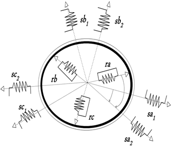
3.1 The DSIM model
The DSIM contains two three-phase windings framework moved by an angle γ (γ=30°) and a common squirrel cage rotor winding as shown in Figure 5 [23, 25].
The dynamics model of the DSIM is written as follow:
$\left\{\begin{aligned} V_{d s 1} &=R_{s 1} i_{d s 1}+\frac{d_{\phi d s 1}}{d t}-\omega_{s} \phi_{q s 1} \\ V_{q s 1} &=R_{s 1} i_{q s 1}+\frac{d_{\phi q} s 1}{d t}+\omega_{s} \phi_{d s 1} \\ V_{d s 2} &=R_{s 2} i_{d s 2}+\frac{d_{\phi d s 1}}{d t}-\omega_{s} \phi_{q s 2} \\ V_{q s 2} &=R_{s 2} i_{q s 2}+\frac{d_{\phi q s 2}}{d t}+\omega_{s} \phi_{d s 2} \\ V_{d r}=0 &=R_{r} i_{d r}+\frac{d \phi_{d r}}{d t}-\left(\omega_{s}-\omega_{r}\right) \phi_{q r} \\ V_{q r}=0 &=R_{r} i q_{r}+\frac{d \phi_{q r}}{d t}+\left(\omega_{s}-\omega_{r}\right) \phi_{d r} \end{aligned}\right.$ (15)
where, the fluxes equations are written as:
$\left\{\begin{aligned} \phi_{d s 1}=L_{s 1} i_{d s 1}+L_{m}\left(i_{d s 1}+i_{d s 2}+i_{d r}\right) \\ \phi_{q s 1}=L_{s 1} i_{q s 1}+L_{m}\left(i_{q s 1}+i_{q s 2}+i_{q r}\right) \\ \phi_{d s 2}=L_{s 2} i_{d s 2}+L_{m}\left(i_{d s 1}+i_{d s 2}+i_{d r}\right) \\ \phi_{q s 2}=L_{s 2} i_{q s 2}+L_{m}\left(i_{q s 1}+i_{q s 2}+i_{q r}\right) \\ \phi_{d r}=L_{r} i_{d r}+L_{m}\left(i_{d s 1}+i_{d s 2}+i_{d r}\right) \\ \phi_{q r}=L_{r} i_{q r}+L_{m}\left(i_{q s 1}+i_{q s 2}+i_{q r}\right) \end{aligned}\right.$ (16)
Figure 5. Schematic representation a DSIM
The electromagnetic torque established by the DSIM can be expressed in terms of the currents and flux as:
$T_{e}=P \frac{L_{m}}{L_{m}+L_{r}}\left(\phi_{d r}\left(i_{q s 1}+i_{q s 2}\right)\right.$$\left.-\phi_{q r}\left(i_{d s 1}+i_{d s 2}\right)\right)$ (17)
with P denotes the number of pole pairs.
The fundamental equation of the movement of the DSIM is given by the expression:
$J \frac{d \Omega_{r}}{d t}=T_{e}-T_{r}-f_{r} \Omega_{r}$ (18)
3.2 Indirect three-level matrix converter (ITLMC)
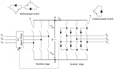
Figure 6 depicts the topology of the ITLMC, which consists of two stages: a rectifier stage and an inverter stage formed by a three-level inverter structure NPC, without any bulky energy storage elements as an intermediate link. They are connected in three points (p,n,o), the points p and n are the outputs of the rectifier and the point o is the neutral point of the filter [26, 27].
Figure 6. ITLMC equivalent circuit
The output voltages of ITLMC are given by:
$\left[\begin{array}{l}V_{a} \\ V_{b} \\ V_{c}\end{array}\right]=\left[\begin{array}{ll}S_{a} & S_{a}^{\prime} \\ S_{b} & S_{b}^{\prime} \\ S_{c} & S_{c}^{\prime}\end{array}\right]\left[\begin{array}{lll}S_{A p} & S_{B p} & S_{C p} \\ S_{A n} & S_{B n} & S_{C n}\end{array}\right]\left[\begin{array}{l}V_{A} \\ V_{B} \\ V_{C}\end{array}\right]$$=F_{i n v} \cdot F_{r e c} \cdot V_{i n}$ (19)
where, $S_{j k}$ represents the switch's state of the matrix converter, $F_{i n v}, F_{r e c}$ are the transfer function of the inverter and the rectifier, and $V_{i n}$ the input voltage, the following statement defines the connection function [29, 30].
For the rectifier stage is defined by:
$S_{j k}=\left\{\begin{array}{c}1 \text { if the switch is closed } \\ 0 \text { if the switch is open }\end{array}\right.$ (20)
For the inverter stage is defined by
$S_{k i}=\left\{\begin{array}{ll}S_{i}=1, & S_{i}^{\prime}=0 \text { for the state } P \\ S_{i}=0, & S_{i}^{\prime}=1 \text { for the state } N \\ S_{i}=0, & S_{i}^{\prime}=0 \text { for the state } 0\end{array}\right.$ (21)
The two space vectors of the input current Iin and the output voltage V0 of the ITLMC are defined by:
$I_{i n}=\frac{2}{3}\left(I_{A}+I_{B} e^{j \frac{2 \pi}{3}}+I_{C} e^{j \frac{4 \pi}{3}}\right)$ (22)
$V_{o}=\frac{2}{3}\left(V_{a}+V_{b} e^{j \frac{2 \pi}{3}}+V_{c} e^{j \frac{4 \pi}{3}}\right)$ (23)
4.1 Problem statement
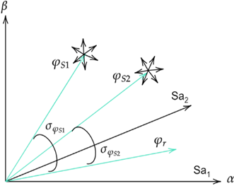
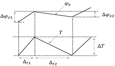
Direct torque control suffers from the high ripples of the torque and flux, especially at low speed. The variable switching frequency in a DTC based on the hysteresis controller is due to the variation of the time taken for the torque error to touch the upper and lower hysteresis bands, which is caused by the variation of the torque slopes with operating conditions. Figure 7 shows the variation slope of the flux and torque waveforms.
Figure 7. Variation waveforms of the flux and torque
It can be seen that the variation of the amplitude of the flux rate is very small when compared to the torque, and we can be noticed that the time taken by the reverse voltage of the torque regulation is long, and is so to affect for the flux regulation.
The incompatible variation of torque slope and the usage of fixed hysteresis bandwidth are the major drawback for variable switching frequency in DTC drives, to eliminate this problem, we proposed a constant switching frequency controller.
4.2 Constant switching frequency controller
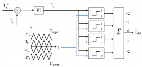
The major problem of the variable switching in the DTC, it caused by the incompatible variation of the torque slope and the usage a fixed torque hysteresis bandwidth, for eliminate this problem we proposed a CSFC, it contains a PI controller, four triangular carriers and four comparators as shown in Figure 9. The PI controller is used for compensating the large variation of torque slope. On the other hand, the output of the PI controller is compared with four triangular carriers to generate output similar to five-level hysteresis controller output (-2, -1, 0, +1, +2). For instance, if the output of the PI regulator it between 2 and 1 the torque regulator will generate an output of high torque request important, we use a large or medium vector, and if the torque request will be lower down (between 0, +1), we use a small vector. Then the output is zero, we use the null vector the switching frequency is constant and it depends on the frequency of the triangular carriers, contrary to the conventional DTC, which is based on the variable frequency of the hysteresis bandwidth. Figure 8 shows this controller.
Figure 8. Proposed torque regulator
4.3 Synergetic speed controller design
In DTC is well known used a controller in the outer speed loop to generate reference torque is the conventional PI. In this paper, we proposed a new robust controller design basing on the synergetic control.
The speed controller generates the reference torque $C_{\text {ref}}$.
The macro-variable will be chosen as:
$\Psi=\Omega_{\text {ref}}-\Omega$ (24)
Then the derivative of it is given by:
$\dot{\Psi}=\dot{S}_{r e f}-\dot{\Omega}$ (25)
The dynamic equation of DSIM is given as:
$\dot{\Omega}=\frac{1}{J}\left(C_{e m}-C_{r}-f_{r} \Omega\right)$ (26)
J: inertia moment, fr: coefficient of friction, Cr: load torque.
By substituting Eq. (26) in the Eq. (25), and basing on the synergetic theory, we can write:
$T\left(\dot{\Omega_{\text {ref}}}-\frac{1}{J}\left(C_{e m}-C_{r}-f_{r} \Omega\right)\right)+\Psi=0$ (27)
$T \dot{\Omega_{r e f}-\frac{T}{J} C_{e m}}+\frac{T}{J} C_{c r}+\frac{T}{J} f_{r} \Omega+\Psi=0$ (28)
The generated reference torque by the synergetic controller is given by:
$C_{e m}=J \dot{\Omega_{r e f}}+C_{r}+f_{r} \Omega+\boldsymbol{\Psi} \frac{J}{T}$ (29)
The synergetic control law must fulfill the Lyapunov stability condition to construct speed control stability. We can use the Lyapunov function to ensure Asymptotic stability:
$V=\frac{1}{2} \Psi(e)^{2}$ (30)
After differentiation one gets:
$\dot{V}=\Psi(e) \dot{\Psi}(e)$ (31)
$\dot{V}=-\frac{1}{T} \Psi^{2}(e) \leq 0$ (32)
Thus, the inequality (32) will ensure the stability of the closed speed control loop.
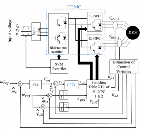
The proposed DTC control of the ITLMC based on the CSFC and synergetic control is therefore done according to the diagram of Figure 9, in which the rectifier is controlled by the SVM technique and the three levels DTC is applied to the inverter.
Figure 9. Overall block diagram of proposed control
To demonstrate the benefits provided by the proposed control, several simulation tests have been carried out for various operating conditions. The simulation is achieved using Matlab/Simulink software. The parameters used in this simulation are Rs1=Rs2=3:72 Ω, Rr=2:12 Ω, Ls1=Ls2=0:022 H, Lr=0:006 H, Lm=0:3672 H, J=0.0625 Kg.m2, Kf=0:001 N.m.s/radand Pn=4:5 KW.
First test
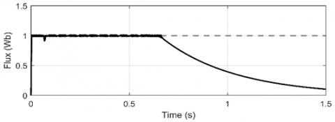
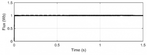
In the first test, we can show the robustness of the proposed controller in low and zero speed region with a light load. In Figure 10, a step reference for the speed change from 0 to 20 rad/s is applied at t=0. At t=0.6, the speed reference is stepped down to 0 rad/s. At low speed, regulation of the stator flux for the DTC-HC fails and the flux cannot be maintained to its rate of 1 Wb (see Figure 11), on the other hand, the flux is maintained high at zero speed for DTC-CSFC (see Figure 12). This indicates the proper flux regulation at zero speed with the light load by the CSFC.
Figure 10. Speed
Figure 11. Flux based on hysteresis controller
The benefits of CSFC are to eliminate the high variation of the torque and to reduce the duration of the reverse voltage vector for flux regulation as shown in the second test.
Figure 12. Flux based on CSFC
Second test
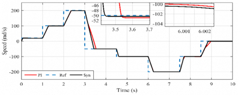
In this test, in order to show the robustness and the stability of the proposed controller in all the possibilities of the speed and the load torque variation, one can take several references. The reason for choosing this reference is to check the static and dynamic performances of the system, thus to show the advantages of the proposed controller compared to the conventional one. As it can be seen in Figure 13, despite the variation in all possibilities of the speed reference (reference constant, low, average and high speed, inversion and zero speed) and the variation of the load torque, the actual speed follows well the reference, and one can also see that the synergetic control has a fast response time and very small tracking error compared to the conventional PI controller.
The torque pursues well the variation of the load torque (Figure 14), it also has a small tracking error and almost equal to the load torque for all the operating ranges studied. Furthermore, it is remarked that the dynamics of the torque in DTC-CSFC are faster and it has much fewer ripples compared to the conventional DTC with hysteresis controller. The aforementioned performances provided by the proposed controller demonstrate the applicability of the CSFC to real-world applications.
Figure 13. Speed of DSIM
Figure 14. Electromagnetic torque
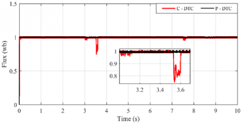
Figure 15. Stator flux magnitude
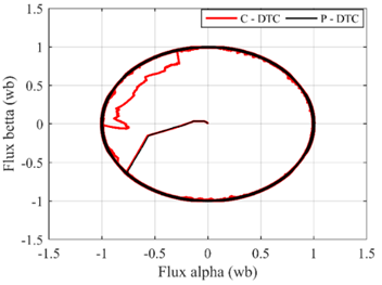
Figure 16. Stator flux circular trajectory
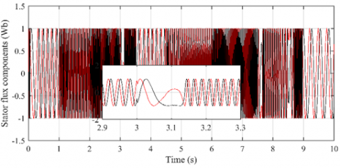
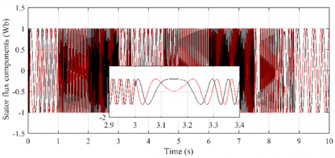
Figures 15-18 respectively show the flux magnitude, the circular trajectory, and axes components, one can see that the use of CSFC can greatly reduce the flux ripples and the flux follows its reference for the entire operating range. Furthermore, the flux practically respects its hysteresis band, it is not exceeded in the case of low speeds and especially during the inversion of the sign of the speed (t=3s and 8s) compared to the conventional one. This reflects the good decoupling between the flux and torque axes that is achieved by the proposed CSFC - based DTC. This is very important when moving from simulation toward real application.
Figure 17. Stator flux axes components based on C-DTC
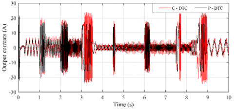
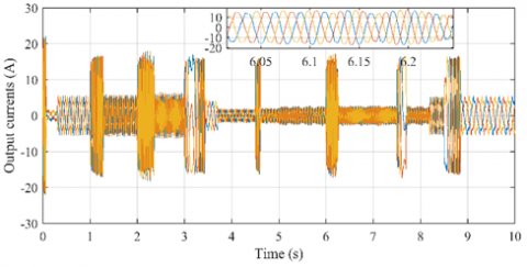
The output currents are practically sinusoidal, they change their amplitude and frequency according to the speed reference and load torque. In addition, there is no distortion in the current waveform with the proposed control, its value is less important compared to the Hysteresis-based DTC, this is remarkable especially when reversing the speed reference at 3 and 8.7 seconds (see Figure 19).
Figure 18. Stator flux axes components based on P-DTC
Figure 19. Output currents with conventional and proposed P-DTC
Figure 20 shows the output currents of DSIM based on DTC-CSFC, the time variation curve is purely sinusoidal, there is practically no distortion in the current wave.
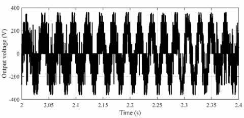
The output voltage is a multilevel voltage (Figure 21), it varies in amplitude and frequency according to the speed reference and the load torque variation.
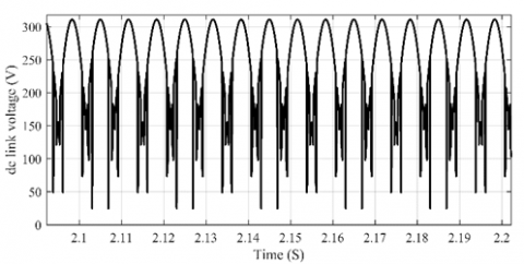
Figure 22 shows the DC-link voltage (Vdc), generated by the modulation of the rectifier stage by the SVM technique. Due to the zero-current vector cancellation for maximizing the output Vdc, the DC-link voltage generated by the rectification stage does not consist of the zero voltage levels so the value of the DC-link voltage, is not constant and the absence of the filtering capacity.
Figure 20. Output currents of DSIM
Figure 21. Output voltage of IMC
Figure 22. Output voltage of the rectifier Vdc
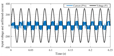
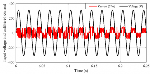
Figure 23. Input voltage and unfiltered current of ITLMC based on C-DTC
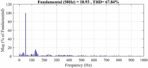
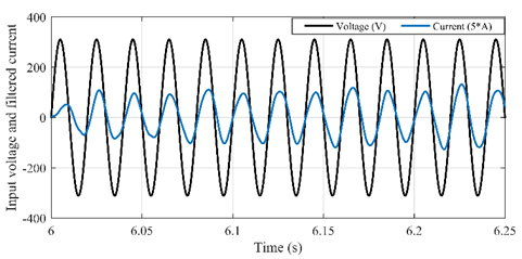
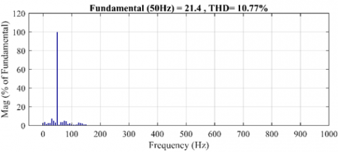
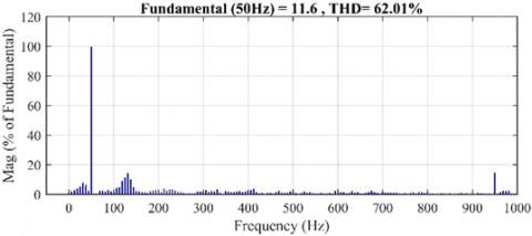
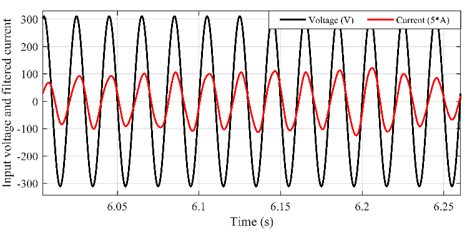
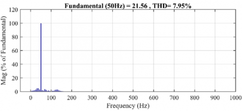
The fundamental of the input current is in phase with the input voltage, which means that the system operates under a unity power factor, in both methods, are shown in Figures (23, 25, 27 and 29). Furthermore, one can remark that the unfiltered input current with the proposed control shown in Figure 28 is full of harmonics and its fundamental is lower (Figure 28, THD=62.01%) than that found with the classical DTC and they are less important (Figure 24, THD=67.84%). The filtered input current (see Figure 25) is also polluted in the classical DTC, especially in the case of transient conditions (Figure 26, THD=10.77%), compared to the proposed control (Figure 30, THD=7.95%). Its THD is important and it is in phase with the input voltage (Figure 30). The CSFC was able to reduce the ripples in the torque and flux, meanwhile to minimize the spectrum harmonics in the input and output currents. Again, this is very important when applying the CSFC-based DTC to a real-world system.
Figure 24. Spectrum harmonic of input voltage and unfiltered current of ITLMC based on C-DTC
Figure 25. Input voltage and filtered current of ITLMC based on C-DTC
Figure 26. Spectrum harmonic of input filtered current of ITLMC based on C-DTC
Figure 27. Input voltage and unfiltered current of ITLMC based on P-DTC
Figure 28. Spectrum harmonic of input unfiltered current of ITLMC based on P-DTC
Figure 29. Input voltage and filtered current of ITLMC based on P-DTC
Figure 30. Spectrum harmonic of input filtered current of ITLMC based on P-DTC
Table 3 shows the comparative analyses between the proposed speed synergetic controller with the classical PI controller, we can comment on the following points:
1- The proposed SC is faster response time and very small tracking error compared to the PI.
2- Speed dropping is weak when load application in the SC compared to PI.
3- Faster torque response time when to load application.
Table 3. Comparative analysis of the various controllers in outer speed loop (PI, SC)
|
Controller |
PI |
SC |
|
Speed response time [sec] |
0.11 s |
0.087 s |
|
Speed dropping due to load application [rad/s, %] |
19.6 rad/s 0.196 % |
19 rad/s 0.19 % |
|
Torque response time to load application [sec] |
0.055 s |
0.045 s |
In this work, a DTC of DSIM based on a CSFC fed by an ITLMC is presented. A robust synergetic speed controller is synthesized instead of using the conventional PI controller. The proposed scheme overcame the major drawbacks of the classical DTC such as the high ripples of the torque and flux caused by the variable switching frequency. Thanks to the proposed controller, the flux regulation at low speed is improved and the THD of the input current is minimized. Moreover, with the introduction of SC, the robustness of the speed controller against load disturbances is enhanced. The simulation results showed a significant improvement in dynamic performances (torque, flux, and speed).
[1] Levi, E. (2008). Multiphase electric machines for variable-speed applications. IEEE Transactions on Industrial Electronics, 55(5): 1893-1909. https://doi.org/10.1109/TIE.2008.918488
[2] Holakooie, M.H., Ojaghi, M., Taheri, A. (2019). Modified DTC of a six-phase induction motor with a second-order sliding-mode MRAS-based speed estimator. IEEE Transactions on Power Electronics, 34(1): 600-611. https://doi.org/10.1109/TPEL.2018.2825227
[3] Barrero, F., Duran, M.J. (2015). Recent advances in the design, modeling, and control of multiphase machines—Part I. IEEE Transactions on Industrial Electronics, 63(1): 449-458. https://doi.org/10.1109/TIE.2015.2447733
[4] Barrero, F., Duran, M.J. (2015). Recent advances in the design, modeling, and control of multiphase machines—Part II. IEEE Transactions on Industrial Electronics, 63(1): 459-468. https://doi.org/10.1109/TIE.2015.2448211
[5] Bojoi, R., Farina, F., Griva, G., Profumo, F., Tenconi, A. (2005). Direct torque control for dual three-phase induction motor drives. IEEE Transactions on Industry Applications, 41(6): 1627-1636. https://doi.org/10.1109/TIA.2005.858281
[6] Pandit, J.K., Aware, M.V., Nemade, R.V., Levi, E. (2016). Direct torque control scheme for a six-phase induction motor with reduced torque ripple. IEEE Transactions on Power Electronics, 32(9): 7118-7129. https://doi.org/10.1109/TPEL.2016.2624149
[7] Takahashi, I., Noguchi, T. (1986). A new quick-response and high-efficiency control strategy of an induction motor. IEEE Transactions on Industry Applications, 22(5): 820-827. https://doi.org/10.1109/TIA.1986.4504799
[8] Taheri, A. (2016). Harmonic reduction of direct torque control of six-phase induction motor. ISA transactions, 63: 299-314. https://doi.org/10.1016/j.isatra.2016.02.014
[9] Tang, L., Zhong, L., Rahman, M.F., Hu, Y. (2004). A novel direct torque controlled interior permanent magnet synchronous machine drive with low ripple in flux and torque and fixed switching frequency. IEEE Transactions on Power Electronics, 19(2): 346-354. https://doi.org/10.1109/TPEL.2003.823170
[10] Wang, F., Zhang, Z., Davari, S.A., Fotouhi, R., Khaburi, D.A., Rodríguez, J., Kennel, R. (2014). An encoderless predictive torque control for an induction machine with a revised prediction model and EFOSMO. IEEE Transactions on Industrial Electronics, 61(12): 6635-6644. https://doi.org/10.1109/TIE.2014.2317140
[11] Viola, J.C., Restrepo, J.A., Guzman, V.M., Gimenez, M.I. (2006). Direct torque control of induction motors using a fuzzy inference system for reduced ripple torque and current limitation. In 2006 12th International Power Electronics and Motion Control Conference, pp. 1161-1166. https://doi.org/10.1109/EPEPEMC.2006.4778559
[12] Idris, N.R.N., Yatim, A.H.M. (2004). Direct torque control of induction machines with constant switching frequency and reduced torque ripple. IEEE Transactions on Industrial Electronics, 51(4): 758-767. https://doi.org/10.1109/TIE.2004.831718
[13] Alsofyani, I.M., Idris, N.R.N. (2015). Simple flux regulation for improving state estimation at very low and zero speed of a speed sensorless direct torque control of an induction motor. IEEE Transactions on Power Electronics, 31(4): 3027-3035. https://doi.org/10.1109/TPEL.2015.2447731
[14] Wheeler, P.W., Rodriguez, J., Clare, J.C., Empringham, L., Weinstein, A. (2002). Matrix converters: A technology review. IEEE Transactions on Industrial Electronics, 49(2): 276-288. https://doi.org/10.1109/41.993260
[15] Rodriguez, J., Rivera, M., Kolar, J.W., Wheeler, P.W. (2011). A review of control and modulation methods for matrix converters. IEEE Transactions on Industrial Electronics, 59(1): 58-70. https://doi.org/10.1109/TIE.2011.2165310
[16] Venturini, M. (1980). A new sine wave in sine wave out, conversion technique which eliminates reactive elements. in Proc. Powercon, 7: E3_1–E3_15.
[17] Huber, L., Borojevic, D. (1995). Space vector modulated three-phase to three-phase matrix converter with input power factor correction. IEEE Transactions on Industry Applications, 31(6): 1234-1246. https://doi.org/10.1109/28.475693
[18] Casadei, D., Serra, G., Tani, A. (2001). The use of matrix converters in direct torque control of induction machines. IEEE Transactions on Industrial Electronics, 48(6): 1057-1064. https://doi.org/10.1109/41.969384
[19] Li, Y., Liu, W. (2007). A novel direct torque control method for induction motor drive system fed by two-stage matrix converter with strong robustness for input voltage. In 2007 2nd IEEE Conference on Industrial Electronics and Applications, pp. 698-702. https://doi.org/10.1109/ICIEA.2007.4318496
[20] Talaeizadeh, V., Kianinezhad, R., Seyfossadat, S.G., Shayanfar, H.A. (2010). Direct torque control of six-phase induction motors using three-phase matrix converter. Energy Conversion and Management, 51(12): 2482-2491. https://doi.org/10.1016/j.enconman.2010.05.011
[21] Levant, A. (2003). Higher-order sliding modes, differentiation and output-feedback control. International journal of Control, 76(9-10): 924-941. https://doi.org/10.1080/0020717031000099029
[22] Kolesnikov, A.A. (2014). Introduction of synergetic control. In 2014 American Control Conference, pp. 3013-3016. https://doi.org/10.1109/ACC.2014.6859397
[23] Moati, Y., Kouzi, K. (2020). Investigating the performances of direct torque and flux control for dual stator induction motor with direct and indirect matrix converter. Periodica Polytechnica Electrical Engineering and Computer Science, 64(1): 97-105. https://doi.org/10.3311/PPee.14977
[24] Li, Y., Liu, W. (2007). A novel direct torque control method for induction motor drive system fed by two-stage matrix converter with strong robustness for input voltage. In 2007 2nd IEEE Conference on Industrial Electronics and Applications, pp. 698-702. https://doi.org/10.1109/ICIEA.2007.4318496
[25] Yahia, M., Katia, K., Khalilsp, M., Saddam, B. (2018). Direct torque control to improve the performances of the DSIM powered by indirect matrix converter. In 2018 International Conference on Communications and Electrical Engineering (ICCEE), pp. 1-5. https://doi.org/10.1109/CCEE.2018.8634447
[26] Lee, M.Y. (2009). Three-level neutral-point clamped matrix converter topology. University of Nottingham; 2009.
[27] Benachour, A., Berkouk, E.M., Mahmoudi, M.O. (2017). A new direct torque control of induction machine fed by indirect matrix converter. Rev. Roum. Sci. Techn. Électrotechn. et Énerg, 62: 25-30.
[28] Mehedi, F., Yahdou, A., Djilali, A.B., Benbouhenni, H. (2020). Direct torque fuzzy controlled drive for multi-phase IPMSM based on SVM technique. Journal Européen des Systèmes Automatisés, 53(2): 259-266. https://doi.org/10.18280/jesa.530213
[29] Moati, Y., Katia, K., Mokhtari, K. (2019). Fixed switching DTC of DSIM powered by NPC-matrix converter. In 2019 1st International Conference on Sustainable Renewable Energy Systems and Applications (ICSRESA), Tebessa, Algeria, Algeria. https://doi.org/10.1109/ICSRESA49121.2019.9182698
[30] Moati, Y., Katia, K., Mokhtari, K. (2019). Improvement of DTC of Wind Energy Conversion System Based on DSIG using Matrix Converter. In 2019 1st International Conference on Sustainable Renewable Energy Systems and Applications (ICSRESA), Tebessa, Algeria, Algeria. https://doi.org/10.1109/ICSRESA49121.2019.9182509