Venkata Subba Rao Pittu* | Srinivasa Rao Gorantla
© 2020 IIETA. This article is published by IIETA and is licensed under the CC BY 4.0 license (http://creativecommons.org/licenses/by/4.0/).
OPEN ACCESS
United Nations indexes that the world’s population will increase drastically, it may increase by 20% and it will be around 970 crores by 2050. However this scenario requires 20% more food to serve this much population, but farming land is decreasing due to pollution, industrialization, and globalization. Cultivation these days is more difficult and increasing the labor cost and pesticides. Enough labor is not available, so labor charges are also increasing which reflects in expenditure for cultivation. In regular spraying system pesticides are sprayed in the whole field. This will increase pesticide costs and pollution. In this proposed system image acquiring Multicopter will move in a pre-defined path in the field is given in a Mission planner firmware. UAV while moving along the pre-defined path captures high-quality RGB pictures in the field and those captured images are tagged with a Global Positioning System (GPS). These pictures are processed by the image processing system using MATLAB software at the ground station and actual disease recognition from the database frame is done. Disease recognition is done along with the tag of the specific diseased area in the field. These tags can help the crew to identify the diseased area spot. This diseased area or plant GPS tag information is used for the creation of a path for pesticide spraying Multicopters and will spray the pesticide in a diseased area or a plant in the field. This will lead to the optimal usage of pesticides.
unmanned aerial vehicle (UAV)/ multicopter, path planning, image acquisition, disease detection
Nowadays there is much population growth worldwide. This leads to rapid industrialization growth and pollution. This, in turn, leads to a decrease in farming land. Experts say that food would be scarce in the future because of the less farming lands. To meet this challenge, we must increase our food production with this limited farming land. So, there is a necessity for the technology to be introduced in the agricultural sector.
Farmers can identify the diseases at the earlier stages with the help of automatic disease detection. Till now they are using the old method to identify the problem by wandering in the whole field. For larger fields, this type of inspection requires many experts to recognize the defect. Unless the old method is economical, it will be time-consuming. Automatic disease detection is a simple and effective method for identifying diseases. Machine vision is given support by this to provide image-based automatic process control, inspection, and robot guidance [1-6]. Image processing based disease detection requires a large number of images covering almost all areas of the field. Manual image acquisition needs more time and faulty area identification could not be possible exactly.
For identifying diseases in the agricultural field various techniques are using. Those are SVM, ANN, fuzzy logic classifiers, vision-based algorithm with masking green-pixels and colour co-occurrence method, K-means clustering algorithm with neural networks, colour co-occurrence with SVM classifier, Gabor filter for feature extraction and ANN classifier, texture segmentation by co-occurrence matrix method, colour co-occurrence texture analysis method, simple threshold, and triangle thresholding segmentation method, Otsu method. In this research work, we used the SVM classifier algorithm for disease detection and this method gives more accurate results [1].
Nowadays drones are playing a vital role in many areas like aerial surveying, cloud monitoring, agriculture, policing and defense applications, power transmission, disaster management, line inspection, photography, structure inspection, wildlife protection, and parcel delivery. Especially in agriculture, drones are been used for spraying of pesticides and the detection of faulty areas. The UAVs (Unmanned Aerial Vehicles) are aerial vehicles without a pilot and they can be operated remotely or in a pre-programmed path. The vehicles are guided autonomously by the intelligent systems and the integrated sensors. Drones are of four types based on the type of aerial platform used. They are Multi Rotor drones, Hybrid VTOL (Vertical Take-Off and Landing) drones, Single Rotor Helicopter and Fixed Wing drones.
Multicopter is a multi rotating rotorcraft that contains more than two rotors. These copters come under the category of UAV and also have the ability of controlled and steady-state operation. High-quality images are required to find the faulty area in the field by using an automatic disease detection program. Low altitude multicopters give accurate and effective results when compared to high altitude copters.
A robot that can be lifted by six rotors and can be propelled is a hexacopter. These six propellers are rotated by BLDC (Brushless DC). Motors are given support by lipo battery and are controlled by a microprocessor-based controller board [6]. Based on the instructions given by the controller board, electronic speed controllers control the BLDC motors.
Figure 1 consists of a pesticide sprayer or high-resolution RGB camera attached to the hexacopter. The hexacopter is arranged with six motors at an equal distance in every corner of it along with a fixed-wing propeller [7]. According to the automatic control unit or remote, the central controlling unit (control board) mediates and controls the UAV. LiPo battery supports motors and controls units. According to the requirement, a high-quality resolution camera with a gimbal setup takes the images and pesticide mechanism sprayer UAV will spray the pesticide in the diseased area or on plants.
This article consists of an autonomous moving agricultural UAV for image acquisition is described in section 2. Image processing system using MATLAB based programming are discussed in section 3. The detection of the faulty area with a diseased tag is described in section 4. Path planning for pesticide spraying UAV is explained in section 5.
Figure 1. Hexacopter schematic diagram and its motion about an axis
Image acquisition in UAVs is done by path planning [8-10], and the image is acquired by a high-resolution camera i.e., First Person View (FPV) camera with the stabilized gimbal. Path planning is nothing, but the aerial movement of UAV is planned in a full-featured firmware mission planner [3, 11-15]. There are so many numbers of firm wares (soft wares) that are present for controlling Planes, Copters, and Rovers. A mission planner is an open-source firmware for controlling any type of UAV.
2.1 The coordinate system for path planning of an Agricultural UAV
The Earth-centred inertial (ECI) frame coordinate system has its origin at the centre of the earth $\{i\}=\left(x_{i}, y_{i}, z_{i}\right)$ and do not rotate with respect to the stars. The Earth-centred Earth-fixed (ECEF) reference frame $\{e\}=\left(x_{e}, y_{e}, z_{e}\right)$ has origin at $O_{e}$ as the Earth center. ECEF is revolving with respect to the ECI with an angular rate of revolution of $\omega_{e}=7.292 \times \frac{10^{-5} r a d}{s}$.
Geodetic frame: Global positioning system (GPS) is using this system. It has latitude, longitude, and height $(\mu, l, h)$.
Geographic Reference Frames: North East Down (NED): Let $\{\mathrm{n}\}=\left(\mathrm{x}_{\mathrm{n}}, \mathrm{y}_{\mathrm{n}}, \mathrm{z}_{\mathrm{n}}\right)$ be a non-inertial system where the UAV's center of gravity lies with the origin of NED. However, NED's directions are oriented analogous to earth's surface geodetic directions. The x-axis of UAV is treated as North, the y-axis of UAV is treated as East and the z-axis of UAV is treated as South of the earth's surface. If UAV is flying at a constant altitude, then there exists constant z on the earth's surface.
Navigation Frame (NAV): NAV is used for a rotated NED-frame where z-axis points towards normally downwards, but x and y axes do not represent true North and East. Angle made between true North and x-axis in the NED frame is called bearing.
2.2 Vehicle coordinate systems
BODY: The body-fixed frame represented by $\{b\}=\left(x_{b}, y_{b}, z_{b}\right)$ which has an origin at multirotor craft’s center and origin moves with respect to craft. The X-axis pointing to the forward direction, Y-axis represents to the right, Z-axis is the height of the craft.
2.3 Vector notation
The position of body frame relative to the NED frame is given by the vector $P_{b n}^{n}$.
2.4 Rotation matrices
This rotational matrix is used to rotate one frame of reference to another. The transformation from Body to NED is represented in special orthogonal matrices $S O(3)$ is represented in Eq. (1).
$S O(3)=\left\{\mathrm{R} | \mathrm{R} \in R^{3 \times 3}, R^{T} R=R^{T} R=I \text { and }|R|=1\right\}$ (1)
where, $R^{3 \times 3}$ is a matrix of order 3.
2.5 Guidance, navigation, and control
A rotation of a vector can be done by the following equation from one frame to another as
$\vec{v}_{R}=R \times \vec{v}_{F}$ (2)
Rotation around a fixed axis is called a simple rotation. The rotation matrices around each axis are given by the Eqns. (3), (4) and (5).
$R_{x}(\emptyset)=\left[\begin{array}{ccc}1 & 0 & 0 \\ 0 & \cos \emptyset & \sin \phi \\ 0 & \sin \varnothing & \cos \phi\end{array}\right]$ (3)
$R_{y}(\theta)=\left[\begin{array}{ccc}\cos \theta & 1 & \sin \theta \\ 0 & 1 & 0 \\ -\sin \theta & 0 & \cos \theta\end{array}\right]$ (4)
$R_{z}(\psi)=\left[\begin{array}{ccc}\cos \psi & -\sin \psi & 0 \\ \sin \psi & \cos \psi & 0 \\ 0 & 0 & 1\end{array}\right]$ (5)
2.6 Rotation between BODY and NED
The vehicle's altitude in terms of Euler's angels roll ($(\phi)$), pitch $(\theta)$ and $\operatorname{yaw}(\psi)$ and rotation angle from BODY to NED is given by means of Euler's angels is given by Eq. (6).
$R_{b}^{n}=R_{z}(\psi) \times R_{y}(\theta) \times R_{x}(\phi)$ (6)
When calculating this, $R_{b}^{n}$ is found as Eq. (7)
$R_{b}^{n}=\left[\begin{array}{l}
s(\theta) c(\psi) \\
c(\theta) s(\psi) \\
-s(\theta)
\end{array}\right.$$\left.\begin{array}{rl}
-c(\phi) s(\psi) & s(\phi) s(\psi) \\
+s(\phi) s(\theta) c(\psi) & +c(\phi) s(\theta) c(\psi) \\
c(\phi) c(\psi) & -s(\phi) c(\psi) \\
+s(\phi) s(\theta) s(\psi) & +c(\phi) s(\theta) s(\psi) \\
s(\phi) c(\theta) & c(\phi) c(\theta)
\end{array}\right]$ (7)
where, $s(*)=\sin *$ and $c(*)=\cos *$.
Generally, UAVs' motions are controlled by three different independent blocks namely Guidance, Navigation, and Control (GNC) system.
The interactions among all the blocks in the GNC system are done by means of data and signal transmissions. Tasks of each subsystem are described briefly as follows:
Guidance: It helps to track continuously the desired position, velocity, and acceleration of multicopter used by the motion control system.
Navigation: It is the duty of multicopter to direct in a way to reach the exact desired position and altitude on calculating course and distance traveled, along with velocity and acceleration too in some cases. This is achieved by using accelerometers/gyros combined with the Global Navigation Satellite System (GNSS) or by advanced navigation systems like the Inertial Navigation System (INS).
Control: It is indeed used to determine control forces and certain moments to be provided to multicopter to reach the desired point. Control objectives are generally set by guidance system and control objectives are nothing but path-following set by the user, target tracking and set-point regulation. The control system in multicopter also gets feedback on tracking from the navigation system.
2.7 Lookahead-based steering
For look head-based steering, the course angle assignment is separated into two parts:
$x_{d}=x_{p}+x_{r}(e)$ (8)
where, $X_{e}=\alpha_{k}$ and $e$ is the cross-track error given by the following Eqns. (9) and (10).
$\alpha_{k}=\tan ^{-1}\left(\frac{y_{k+1}-y_{k}}{x_{k+1}-x_{k}}\right)$ (9)
$y e(t)=-\left\{x(t)-x_{k}\right\} \sin \alpha_{k}+\left\{y(t)-y_{k}\right\} \cos \left(\alpha_{k}\right)$ (10)
When the waypoints are dented $\left(x_{k}+y_{k}\right)$ and $\left(x_{k+1}+y_{k+1}\right)$
For calculating $x_{r}(e)$, offers some variants. The one used in this paper
$x_{r}=\tan ^{-1}\left(-K_{p} e\right)$ (11)
where, $K_{p}$ design variable is given by Eq. (12).
$K_{p}(t)=\frac{1}{\sqrt{R^{2}-e(t)^{2}}}>0$ (12)
where, R is chosen.
2.8 Head for next waypoint
When a multicopter is moving in a linear path made up of n straight lines associated by $n+1$waypoints, the choice of next waypoint done by checking the multicopter is lain the predefined region of radius $R_{k+1}$ around the waypoint $\left(x_{k+1}, y_{k+1}\right)$ verify by using the Eq. (13).
$\left[x_{K+1}-x(t)\right]^{2}+\left[x_{k+1}-y(t)\right]^{2} \leq R_{k+1}^{2}$ (13)
Waypoints can also be changed by considering the criterion of track distance by the following Eq. (14).
$s(t)=\left[x(t)-x_{k}\right] \cos \left(\alpha_{k}\right)+\left[y(t)-y_{k}\right] \sin \alpha_{k}$ (14)
where, $\alpha_{k}$ is given by Eq. (9).
Change of waypoint has to be done only when the multicopter can move wholly the distance between two-way points i.e done by the following Eq. (15). is true
$s(t)+d s \geq \sqrt{\left(x_{k}-x_{k+1}\right)^{2}+\left(y_{k}-y_{k+1}\right)^{2}}$ (15)
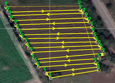
where, $d_{S}$ distance between the two beside waypoints for multicopter switching. Mission Planner creates a mission for you, which is useful for a function like mapping missions shown in Figure 2. where the aircraft should just go back and forth in a “lawnmower” pattern over an area to collect photographs.
Figure 2. Path planning in Mission planner to acquire images
Multicopter is used to capture images of the field with GPS latitude and longitude tags. For this inbuilt GPS tracker, high-resolution cameras, stabilized gimbals, FPV and autonomous navigation system to go along the desired path is required. multicopter with all these components travel along the pre-defined path and take pictures of the field within a specific time. These pictures are stored in a memory device on UAV and can also be transmitted to the ground station using wireless routers/telemetry. As the multicopter travels along the pre-defined path then it captures images continuously along the traveling path and transmits data to ground stations.
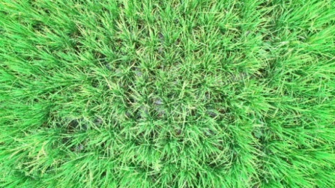
Figure 2 shows the pre-defined path for multicopter can be given in mission planner software and the UAV will move according to the given path and acquires the images with GPS information. For this, multicopters are equipped with an inbuilt GPS tracker, Internal Measuring Unit (IMU), stabilized gimbal, high-resolution camera, an autonomous navigation system, and FPV. The pictures taken by the multicopters are directly stored in the memory device and also able to transmit directly to the ground station. The multicopter will fly in a predefined path and take the pictures continuously and store the data in memory or transmit data to the ground station. Figure 3 is a picture captured by the UAV over the field.
Figure 3. RGB image acquired by hexacopter
After getting the images from the image acquiring process images might have affected by the intensity of light, the noise of the image and distortion. This can be eliminated by the convolution neural network technique [16].
Acquired images can be processed in the image processing system that consists of different steps like image enhancement, image segmentation and disease detection [1-3, 17, 18]. Primarily acquired images are enhanced and later on green-coloured pixels in the image are masked based on the threshold limit of the set value of the green pixel. If the green pixels are masked, then it is assigned as zero and those pixels turn to black color. Then the remaining pixels which are not black are segmented. Based on the image segmentation, clusters can be formed and on choosing one of the clusters, a specific disease can be detected when comparing the pixel properties with the disease database already framed [5].
The k means clustering is an algorithm that is used to identify the pixels into k number of classes [4]. It is done by a minimal sum of squares of the distance between the pixels corresponding cluster center. Generally, it is done for 3 or 4 numbers of clusters to identify 3 to 4 diseases in a plant.
Let cluster center $z_{j}$ for $j=1,2,3, \ldots, k$ by the following equation
if $\left\|x_{i}-z_{j}\right\| \leq\left\|x_{i}-z_{l}\right\|$
$i=1,2,3 \ldots ., m \times n, l=1,2,3 \ldots k, \text { and } p \neq j.$
Here m x n is the color image and every pixel has Red, Green, and Blue components, i indicates the pixel number and cluster number.
The cluster center can be represented as
$z_{i}(r, g, b)=\frac{1}{n_{i}} \sum_{x_{j} \in c_{i}}\left(x_{j}(r, g, b)\right)$
$i=1,2,3 \dots k$ (16)
Now the fitness function is computed by calculating Euclidean distance between the pixels and their respective cluster by using the following Eqns. (17) and (18).
$m=\sum m_{i}$ (17)
$m_{i}=\sum_{x_{j} \in c_{i}}\left|\left(x_{j}(r, g, b)-z_{i}(r, g, b)\right)\right|$ (18)
Here the new center of the cluster is $z_{i}$ of a cluster $c_{i}$.
The co-occurrence method can be used to extract the features from the image color. This method considers the color and texture of the image. In this method, RGB images are converted to Hue Saturation Intensity (HIS) image representation. However, in the visible light spectrum, image additional features can also be characterized, and the color co-occurrence features called contrast, homogeneity, energy, and entropy can be obtained by the equations (19), (20), (21) and (22) respectively [19, 20].
contrast $=\sum_{i, j=0}^{n-1}(i, j)^{2} c(i, j)$ (19)
Energy$=\sum_{i, j=0}^{n-1} c(i, j)^{2}$ (20)
Local Homogenity $=\sum_{i, j=0}^{n-1} \frac{c(i, j)}{\left(1+(i-j)^{2}\right)}$ (21)
Entropy$=-\sum_{i, j=0}^{n-1} c(i, j) \log c(i, j)$ (22)
For specific disease detection, the SVM classifier is used to compare the extracted properties of the image by co-occurrence method with a stored data set values. SVM classifier uses minimum distance criterion for disease classification [2, 17]. Classification success is calculated by equation (23).
$\text {Gain } \%=\frac{\text {Number of Correct Classification}}{\text {Total number of test images}}$
$\times 100$ (23)
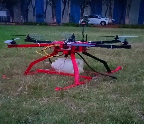
Figure 4. Experimental Setup for image acquisation
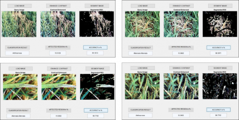
Figure 5. Diseases detected by using image processing in MATLAB
The experimental setup of autonomous UAV is shown in Figure 4, which depicts the top and side views of hexacopter. The designed hexacopter has mainly six propellers run by six BLDC motors, an 11.1 V LiPo battery, six ESCs, Pixhawk Controller Board, GPS tracker, and camera gimbal. By using image processing in MATLAB, the farmer can identify healthy and unhealthy plants. This disease data tells the disease properties, infected area, remedy methods and suggest suitable pesticide for that area.
On programming all the image processing segments in MATLAB, it is possible to compare the captured images with actual data set and thereby, healthy and unhealthy plants can be detected. The advantage in addition is that each image will be tagged with an exact GPS location.
Figure 5 shows the identification of disease by image processing in MATLAB. The query image in Figure 5 is the uploaded image, where it is enhanced by the contrast enhancer technique where it helps to improve the quality of the picture. Further, it is processed by k-means clustering with that region of interest and finally, SVM classifier algorithm will check the pre-defined data set of disease features and identify the disease in that area. The GPS information of the captured image by UAV’s camera is shown in Figure 6. and Table 1. GPS information is nothing but Latitude, Longitude and altitude of the drone position in terms of degrees, minutes and seconds must be changed to only decimal degrees by using the Eq. (24). as it is required to use decimal degrees in the mission planner to find the exact positions of the diseased plant area.
$\begin{aligned} \text { Decimal Degrees } &=\text { Degrees }+\left(\frac{\text {Minutes}}{60}\right) \\ &+\left(\frac{\text {Seconds}}{3600}\right) \end{aligned}$ (24)
Figure 6. GPS information of drone capture diseased image
Table 1. GPS information for a diseased plant
|
S. No. |
Latitude in Degrees Minutes Seconds (D° M' S") |
Longitude in Degrees Minutes Seconds (D° M'S") |
Altitude in feet |
Latitude in Decimal Degrees |
Longitude in Decimal Degrees |
Disease information |
Accuracy % |
|
1 |
16° 27' 40.6614" |
80° 40' 49.08" |
88.175 |
16.4612950 |
80.6803000 |
Cercospora Leaf Spot |
92.1711 |
|
2 |
16° 27' 40.6722" |
80° 40' 47.1858" |
87.275 |
16.4612976 |
80.6797743 |
Anthracnose |
95.1613 |
|
3 |
16° 27' 40.32" |
80° 40' 48.126" |
87.285 |
16.4611999 |
80.6800345 |
Cercospora Leaf Spot |
92.3881 |
|
4 |
16° 27' 40.6974" |
80° 40' 49.872" |
87.275 |
16.4613053 |
80.6805199 |
Cercospora Leaf Spot |
89.8813 |
|
5 |
16° 27' 40.1328" |
80° 40' 49.7856" |
87.275 |
16.4611484 |
80.6804958 |
Alternaria Alternata |
98.3871 |
|
6 |
16° 27' 39.6246" |
80° 40' 47.5638" |
80.175 |
16.4610070 |
80.6798789 |
Alternaria Alternata |
96.7742 |
|
7 |
16° 27' 39.513" |
80° 40' 49.3392" |
88.175 |
16.4609761 |
80.6803724 |
Alternaria Alternata |
95.4471 |
|
8 |
16° 27' 39.1248" |
80° 40' 50.343" |
87.275 |
16.4608681 |
80.6806514 |
Anthracnose |
96.7742 |
|
9 |
16° 27' 39.0414" |
80° 40' 48.6552" |
87.275 |
16.4608449 |
80.6801820 |
Alternaria Alternata |
88.5462 |
|
10 |
16° 27' 38.595" |
80° 40' 48.867" |
87.275 |
16.4607214 |
80.6802410 |
Cercospora Leaf Spot |
90.1283 |
|
11 |
16° 27' 38.6706" |
80° 40' 50.4222" |
87.275 |
16.4607420 |
80.6806728 |
Anthracnose |
98.3871 |
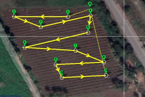
Table 1 gives information about the disease and its longitude and latitude. This GPS information is used in the mission planner for providing a path to the diseased area. Figure 7 shows the overall layout of the field with infected areas and diseases where the yellow lines represent the path and green tags represent the infected plant area.
In the pesticide spraying mechanism, the UAV must reach the destination with a specified altitude in the predefined path. After reaching the waypoint the servo mechanism of the spray system must be activated and it must stay some time at that waypoint and then it has to move for next waypoint. After completion of its spraying, it must move to its home position.
Figure 7. Disease information (green tags) in GPS and Path for pesticide spraying UAV
For this we have given commands in mission planner software which is shown in Figure 8 The Second column in Figure 8 indicates the activation of servo mechanism for spraying, column 3 is for delay time at that waypoint is given by 5 seconds, column 6 and 7 indicate GPS information provided for waypoints to the diseased area and column 8 is for the height of the UAV at that waypoint and it is given as 10feet from the ground.
Figure 8. Path planning and pesticide spraying mechanism in Mission planer firmware
Figure 9 is showing the experimental setup of hexacopter which is made of an aluminum frame with six 360 kV BLDC motors of which each motor will produce 1.2 kg of thrust, six 40 A electronic speed controllers (ESCs), one Pixhawk controller board with telemetry and GPS, a battery of capacity 5000 mAh and one sprinkler system which can be able to produce 7.2 kg of total thrust and able carry the payload of 1.3 Kg.
Figure 9. Experimental setup for pesticide spraying UAV
This research work explains how UAVs are used for agricultural applications. This work focuses on image acquisition, path planning, disease detection and pesticide spraying in the diseased area. For these two UAVs or multi-copters are used. One is for image acquisition which consists of 1500 grams weight, small, moves on the overall field and consumes less power. The other is for pesticide spraying which consists body weight of 2.2 kg and pesticide weight (payload) of 1.3 kg. It consumes more power and it moves only to the diseased part of the field. For the disease detection SVM classifier algorithm is used. It gives more than 90% accurate results when compared to the other algorithms.
Basing on this system the formers will be able to reduce the wastage of time and money. It also helps in the optimal usage of pesticides. So that the formers will get rid of more exposure to the pesticides and helps in the reduction of soil pollution.
[1] Singh, V., Misra, A.K. (2017). Detection of plant leaf diseases using image segmentation and soft computing techniques. Information processing in Agriculture, 4(1): 41-49. https://doi.org/10.1016/j.inpa.2016.10.005
[2] Mohan, K.J., Balasubramanian, M., Palanivel, S. (2016). Detection and recognition of diseases from paddy plant leaf images. International Journal of Computer Applications, 144(12). https://doi.org/10.5120/ijca2016910505
[3] Khirade, S.D., Patil, A.B. (2015). Plant disease detection using image processing. In 2015 International Conference on Computing Communication Control and Automation, IEEE, pp. 768-771. https://doi.org/10.1155/2018/6070129
[4] Al-Hiary, H., Bani-Ahmad, S., Reyalat, M., Braik, M., ALRahamneh, Z. (2011). Fast and accurate detection and classification of plant diseases. International Journal of Computer Applications, 17(1): 31-38. https://doi.org/10.5120/2183-2754
[5] Qin, Z., Zhang, M., Christensen, T., Li, W., Tang, H. (2003). Remote sensing analysis of rice disease stresses for farm pest management using wide-band airborne data. In IGARSS 2003. 2003 IEEE International Geoscience and Remote Sensing Symposium, 4: 2215-2217. https://doi.org/10.1109/IGARSS. 2003. 1294393
[6] Kotarski, D., Piljek, P., Matija, K. (2016). Mathematical modelling of multirotor UAV. International Journal of Theoretical and Applied Mechanics, 1: 233.
[7] Alaimo, A., Artale, V., Milazzo, C., Ricciardello, A., Trefiletti, L. (2013). Mathematical modeling and control of a hexacopter. In 2013 International Conference on Unmanned Aircraft Systems (ICUAS), pp. 1043-1050. https://doi.org/10.1109/ICUAS.2013.6564793
[8] Almadhoun, R., Taha, T., Seneviratne, L., Zweiri, Y. (2019). A survey on multi-robot coverage path planning for model reconstruction and mapping. SN Applied Sciences, 1(8): 847. https://doi.org/10.1007/s42452-019-0872-y
[9] De Rango, F., Potrino, G., Tropea, M., Santamaria, A. F., Palmieri, N. (2017). Simulation, modeling and technologies for drones coordination techniques in precision agriculture. In International Conference on Simulation and Modeling Methodologies, Technologies and Applications, Springer, Cham. pp. 77-101. https://doi.org/10.1007/978-3-030-01470-4_5
[10] Luo, C., Miao, W., Ullah, H., McClean, S., Parr, G., Min, G. (2019). Unmanned aerial vehicles for disaster management. In Geological Disaster Monitoring Based on Sensor Networks, Springer, Singapore, pp. 83-107. https://doi.org/10.1007/978-981-13-0992-2_7
[11] Fu, Z., Yu, J., Xie, G., Chen, Y., Mao, Y. (2018). A heuristic evolutionary algorithm of UAV path planning. Wireless Communications and Mobile Computing. https://doi.org/10.1155/2018/2851964
[12] Andritoiu, D., Bazavan, L.C., Besnea, F.L., Roibu, H., Bizdoaca, N.G. (2018). Agriculture autonomous monitoring and decisional mechatronic system. In 2018 19th International Carpathian Control Conference (ICCC), pp. 241-246.
[13] Jiang, H., Elbaum, S., Detweiler, C. (2017). Inferring and monitoring invariants in robotic systems. Autonomous Robots, 41(4): 1027-1046. https://doi.org/10.1007/s10514-016-9576-y
[14] Paula, N., Areias, B., Reis, A. B., Sargento, S. (2019). Multi-drone control with autonomous mission support. In 2019 IEEE International Conference on Pervasive Computing and Communications Workshops (PerCom Workshops), Springer, Singapore, pp. 918-923. https://doi.org/10.1109/PERCOMW.2019.8730844
[15] Jun, M., D’Andrea, R. (2003). Path planning for unmanned aerial vehicles in uncertain and adversarial environments. In Cooperative Control: Models, Applications and Algorithms, Springer, Boston, MA, pp. 95-110. https://doi.org/10.1007/978-1-4757-3758-5_6
[16] Rajmohan, R., Pajany, M., Rajesh, R., Raman, D.R., Prabu, U. (2018). Smart paddy crop disease identification and management using deep convolution neural network and SVM classifier. International Journal of Pure and Applied Mathematics, 118(15): 255-264.
[17] Vivaldini, K.C., Martinelli, T.H., Guizilini, V.C., Souza, J.R., Oliveira, M.D., Ramos, F.T., Wolf, D.F. (2019). UAV route planning for active disease classification. Autonomous Robots, 43(5): 1137-1153. https://doi:10.1007/s10514-018-9790-x
[18] Mohanty, S.P., Hughes, D.P., Salathé, M. (2016). Using deep learning for image-based plant disease detection. Frontiers in Plant Science, 7: 1419. https://doi.org/10.3389/fpls.2016.01419
[19] Treboux, J., Genoud, D. (2018). Improved machine learning methodology for high precision agriculture. In 2018 Global Internet of Things Summit (GIoTS), pp. 1-6. https://doi.org/10.1109/GIOTS.2018.8534558
[20] Saha, A.K., Saha, J., Ray, R., Sircar, S., Dutta, S., Chattopadhyay, S.P., Saha, H.N. (2018). IOT-based drone for improvement of crop quality in agricultural field. In 2018 IEEE 8th Annual Computing and Communication Workshop and Conference (CCWC), pp. 612-615. https://doi.org/10.1109/CCWC.2018. 83016