Achour El Hamdaouy* | Issam Salhi | Mohamed Dahbi | Driss Oulad-Abbou | Said Doubabi
© 2020 IIETA. This article is published by IIETA and is licensed under the CC BY 4.0 license (http://creativecommons.org/licenses/by/4.0/).
OPEN ACCESS
In this paper, a new controller, management and security system (CMSS) was proposed to ensure the overall operation of pico-hydroelectric power plants (PHPPs) at low-cost, especially in off-grid sites in remote areas. The proposed system can be used to meet the requirements of the PHPP such as the start-up, the departures’ management, the load-frequency controller (LFC), the emergency stop (ES), and the normal stop procedures in order to guarantee good quality and sustainable services. The system was tested under various conditions to prove its reliability using PHPP prototype. Based on the prototype, the laboratory experimental results are presented. The design’s details and the implementation of the system are given as well. The system is completely independent, and it achieved an initial cost of only 266 $. The flexibility makes the system more suitable for extended future improvement such as adding data-logger, adding communication aspects using wireless technologies, etc. Furthermore, the system could be easily adapted for different educational purposes, especially for universities with limited resources.
renewable energy, Pico hydroelectric power plant, low-cost prototype, load-frequency controller, management and controller systems
Nowadays, the power demand is increasing faster and the produced power couldn't keep up with this growth. However, the balance of the energy demand and the use clean and renewable energies is an essential approach for the development path with low carbon emission [1-3]. The renewable energies such as solar, hydro and wind, could be an attractive alternative. In this context, it is suitable to build run-of-river pico-hydroelectric power plants (PHPPs) in remote mountainous regions that cannot be connected to national electric grid [4, 5].
The majority of PHPPs installed in remote mountainous areas are known to be inefficient when failure cases occur. To reset the system, a technician should be present on site. The access to such locations is usually difficult especially during winter and the administration process could take months. Hence, the local population might live without electricity for months. The use of fuel gas backup generators is not suitable for the following reasons: the price of KWH became expensive and the fuel requires delicate transportation on mountain tracks. To overcome such issues, it is necessary to equip the PHPP installations with a powerful controller and management system that can permanently guarantee the electricity generation without any human intervention. Therefore, the system should be autonomous, simple, efficient and easy to maintain.
In the literature, a controller, management and security system (CMSS) of PHPP using a programmable logic controller (PLC) was developed in the paper [6]. However, the proposed system does not have enough inputs/outputs (I/O). If more I/O are needed for extended future improvement, a PLC with enough I/O would be recommended. Therefore, the system cost increases proportionally to the number of I/O provided by the PLC. On the other hand, the presented system uses a PLC’s proportional integral derivative (PID) bloc which maintains the frequency around its standard value. The system does not have the flexibility to improve the PHPP frequency response using advanced controllers [7-9], while the PHPP system is non-linear system [4, 5, 10-12]. The proposed controller could not guarantee good performances for all operating points. For these reasons, open-source technologies could be an attractive option to be used to build PHPP management system.
Arduino software and hardware could be a good alternative to design such system, with a compromise between the reasonable price and good performances. The open-source nature of Arduino has been the main reason for its rapid horizontal growth. The choice is justified by the initiation to physical programming i.e. the interaction between the users and objects. Besides, Arduino is not only the hardware part, but it is also a simple programming language, inspired from C/C++ language, using its integrated development environment (IDE) adaptable with any computer software (Windows, GNU/Linux, etc.).
The literature includes several papers treated low-cost prototypes using open-source technologies [13-19]. Fuentes et al. [13] have proposed a portable data logger based on Arduino open-source for photovoltaic (PV) monitoring. The data logger is intended for both solar energy research and different applications in developing countries. An inexpensive Arduino-based light-emitting diode (LED) simulator system was developed for research [14]. The system reduces design complexity. According to the paper [16], the authors have proposed an electrochemical impedance spectroscopy system based on Arduino device for in situ corrosion monitoring of metallic works of art. Osufu et al. [17] have designed a load-frequency controller (LFC) system for a micro hydro power plant based on Arduino technologies. However, the proposed system takes into consideration the frequency regulation only.
The main objective of our paper is to propose a novel low-cost CMSS for single-phase PHPP prototype. The designed system allows realizing the main sequences of PHPP such as start-up, departures’ management, LFC, emergency stop (ES), normal stop procedures, etc. The system, including all components of the overall system (PHPP system and the proposed CMSS), is designed. It uses different Arduino boards to monitoring all PHPP operation, which optimizes and leads to better produced energy quality. The performance of the developed CMSS was evaluated, under several conditions, through five scenario tests. In addition, the suggested CMSS is simple and easy to maintain with spare parts available on the local market and software is free, making it affordable to any research and academic structure unit. On the other hand, the designed system could be also used for educational purposes where: (i) the students would validate the studied frequency regulation techniques using their controllers; (ii) the students could master different programming skills using numerous Arduino broads; (iii) the designed system could give more opportunities for students to add more complex functions (WIFI, GSM connections, etc.) based on Arduino and learn from them.
Using the proposed system in off-grid sites, the local communities could benefit from a sustainable access to electricity and from other basic facilities such as improves the preservation of foods destined to be placed in markets, electric tools, or communication and information devices. Additionally, it strongly promotes the development of entrepreneurship and new local business.
The next section presents the PHPP prototype and its essential components. The proposed CMSS is designed in the third section. The fourth section deals with five tests under various PHPP operation conditions. The analysis cost of the proposed CMSS is discussed in the fifth section. The last section of the paper presents a conclusion and some promising horizons for both educational and research fields.
The PHPP is a hydro-electrical energy converter that converts the hydro energy into electricity. Typically, a process of electricity generation from PHPP involves several technologies such as run-of-river. The method consists of diverting a portion of a river from intake through a channel to surge tank. Then, the water is released in the penstock; it flows through until a hydraulic turbine and spins it. The turbine is generally directly coupled to a generator. The generator rotation produces electricity. The PHPP uses the run-of-river type flow of the water and does not require the construction of a large dam.
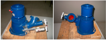
The importance of this kind of electricity generation system brings the authors to build a laboratory prototype with reduced power (200W). The prototype and all its components should emulate the real PHPP’s operation. Figure 1 illustrates the PHPP prototype (without any control or management system).
The proposed prototype is composed from:
The installation permits to adjust the water flow, using a manual gate, from 0 to 20 l/s at the turbine entrance. The nominal parameters of this installation are shown in Table 1.
Figure 1. The experimental rig: single-phase PHPP
Figure 2. Turbine-generator group of the prototype
Table 1. Installation parameter values
|
Electric power |
200 W |
|
Frequency |
50 Hz |
|
Nominal voltage |
220 V |
|
Nominal flow |
6.5 l/s |
|
Nominal speed |
1400 rpm |
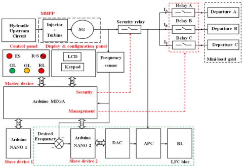
The CMSS of PHPP, including all components of the proposed system, is presented. A global schematic diagram of the system including the PHPP components is described in Figure 3. As it can be seen, an Arduino MEGA board [20], called master device, is used to manage the other devices and make appropriate decisions, give order to different actuators, and display information about the system operation state using a liquid-crystal display (LCD).
Figure 3. Global schematic diagram of the overall system, including the proposed system and the PHPP prototype
The master device, presented in Figure 3, has two outputs. The first output "Security" concerns the security system commands. The second output "Management" deals with the management system commands.
The proposed system uses a human-machine interaction (HMI) to ensure a smooth global operation of the PHPP. The HMI is designed through an LCD display and a keypad. The LCD display is used to provide important information about the system such as frequency, state of departures. The system uses GDM1604B LCD (XIAMEN OCULAR brand) [21]. Regarding the keypad, it is used to enter the access password and then can be used to modify the frequency controller’s parameters. The used keypad contains 4 lines connected at the outputs and 4 columns connected at the inputs are linked with inputs/outputs of Arduino MEGA.
Optocouplers (CNY17Y) [22] were added between the Arduino MEGA and different electromagnetic relays. The optocoupler device is suitable for signal transmission between two electrically separated circuits. The device ensures a safety operation condition between control devices (Arduino MEGA) and power components of PHPP.
To display the instantaneous variation of the frequency, a frequency sensor DIP 605 C (ARDETEM brand) [23] has been connected in parallel (Figure 3) with the mini-load grid. The sensor allows both the display of the measured frequency value and delivers at its output a normalized voltage (0-10V) proportional to the frequency value.
The proposed system contains three different lights (red, orange and green). Each light has a specific role. The green light (GL) switches ON when the PHPP is in operation mode. When the PHPP is in normal stop procedure or ES, the red light (RL) switches ON. The orange light (OL) switches ON when the management system needs to give an order to the PHPP’s operator for opening or closing the turbine’s gate.
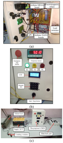
Figure 4 shows the final prototype of the proposed CMSS, including all closed-loop’s components. An electrical cabinet is used to store and safe electrical equipment such as the printed circuit board (PCB), the analog power controller (APC), the different display, indicator lights and control panel. Safety equipment enhances equipment lifespan and safety for operators.
Figure 4. Final prototype of the proposed CMSS. (a) Front view of the proposed system, including different lights, buttons, LCD, keypad and frequency sensor. (b) View of the interior, including the PCB of the proposed system, APC using in LFC closed-loop and load switches. (c) All components of LFC, including ballast load (BL)
3.1 Controller system
In off-grid sites, the PHPP grid power consumption is highly variable and unpredictable. This issue creates a frequency and voltage instabilities. Thus, a controller system is required. In the literature, there are several known PHPP frequency regulations which have been widely used [10, 24-27]. The first, the speed-flow controller (SFC) consists to adjust the water flow reaching the hydraulic turbine in order to keep constant turbine speed (frequency constant). This solution has the advantage of using water economically. However, this technique cannot provide good results when the load variation is large that can lead to the instability of the system. To overcome these issues, the LFC technique is used. It regulates the frequency by dividing the produced power between consumers and a BL [5-7]. The technique has the advantage of having short response time when rejecting sudden consumption fluctuations. The LFC approach is currently the most adopted technique in PHPP system.
In this work, the LFC structure, illustrated in Figure 5, is adopted for the PHPP frequency regulation. The goal is to dissipate the produced excess power on the BL. The APC is controlled by a control signal calculated by a PI controller. The APC is controllable through the voltage (α) which varies between 0V and 10V. When the voltage equal to 10V that is to say, the APC dissipates the total produced power in the BL and when the voltage equal to 0V that is to say, the APC does not dissipate the produced power in the BL.
Figure 5. Schematic diagram of the LFC
The PI controller is widely used in industrial processes. The simplicity and robustness are the most significant benefits for this controller. Several methods exist in the literature for synthesizing their parameters [28, 29]. The proposed controller acts directly on the APC to dissipate the excess power on the BL. The PI frequency controller provides at its output the estimation of the active power unbalanced between the generation and the consumption.
The PI controller expression can be written by (1):
$P I(\varepsilon)=k_{p}(\varepsilon)+\int K_{i} \varepsilon d t$ (1)
with: $k_{p}, K_{i}$ are respectively the proportional and the integral gains of the PI controller and $\varepsilon$ is the tracking error between the set point and the system output (frequency).
The controller parameters could be easily adapted to any configuration of hydroelectric power plant. For this reason, a practical method is the best. Indeed, the Ziegler-Nichols method approximation is used to synthesize the PI controller. After that, the obtained parameters ($k_{p}$ and $K_{i}$) have been set optimally by successive tests to minimize the integral of the squared error (ISE) using Matlab/Simulink environment:
$I S E=\int_{0}^{T} \varepsilon^{2}(t) d t$ (2)
The obtained PI controller parameters using the ISE are: kp=0.75 and ki=0.022.
The proposed LFC (Figure 2) is composed from an Arduino NANO 2 board, a digital-analog converter (DAC), APC and BL. When the Arduino NANO 2, called slave device 2, receives an order from the master device, immediately the slave device 2 starts elaborating the control law based on the evolution frequency of the system. Then, the use of DAC is obligatory to make digital-analog (DA) conversion a specific range [0-5V]. The system uses the PCF8591 like DAC. The PCF8591 is an I2C (inter-integrated circuit) device that contains 4 inputs and one analog output, all operate with 8-bits resolution. The converter can be used as analog-digital (AD) or DA converter. Further, the system needs an additional bloc adaptation between the DAC and the APC using a simple gain through an operational amplifier LM324N. Finally, the described process chain can keep the output frequency of electrical PHPP output in its nominal value (50 Hz) when applying different load discharges or overloads.
3.2 Management system
The electrical mini-load grid (Figure 3) is divided in three separated departures (departure A, departure B, and departure C) with different order of priority. Departure A is considered the highest priority departure and departure C is the lowest priority departure. For instance, departure A could be used to supply the off-grid site’s hospital and the lowest priority departure could be used for public lighting. The proposed strategy could empower the local communities to manage the efficiency of the produced power in ways to keep the PHPP more satisfying and in sustainable operation mode.
The departures’ repartition is realized by using three controllable electromagnetic relays 12 VDC. The master device is considered the main component in our management system. The management system is programmed to make quick and good decisions during the operation of the PHPP, in order to manage all start-up, normal stop procedures, ES, and the management of the three departures to guarantee good quality and continuous services to the local consumers. All decisions are based on the frequency evolution of the system. The proposed management system operates as follows:
The proposed CMSS should all the time monitoring the PHPP operation without interruption time between measurements. For this reason, a second Arduino NANO 1 is proposed, called slave device 1. The main NANO 1 goal is to deal with all timing of departures’ management.
3.3 Security system
The security system is proposed to respond to important tasks in protecting all electrical and mechanical components. There are many issues that PHPP can face such as: (i) an abrupt shedding of the mini-load grid connected to the PHPP. In fact, the turbine speed would increase to reach the over-speed [13]. In our case, the amplitude voltage varies proportionally with the frequency. This variation could damage the FLC’s components; (ii) If the frequency is higher than 55 Hz and the FLC system is not able to establish it; (iii) If the frequency becomes lower than 45 Hz and the management system with their actions are not able to establish the frequency. In fact, there are many causes for that such as the highest priority departure could consume more than the produced power. Or, the turbine shaft could trap by tree pieces. Therefore, if the PHPP plant suffers from the described issues, an ES is necessary.
The proposed security hardware puts at the disposal of the operator an ES button (Figure 4 (b)) which can make immediately an ES of the plant when the operator notices any failure of mechanical or electrical components.
An electromagnetic relay of 12 VDC, called "Security relay" in Figure 3, is set up and controlled by the security system. The idea consists to separate the PHPP prototype and its CMSS and performs a total stop of the overall system. The choice of the timing ranges and over-speed value are determined according to the nominal permissible voltage values of the controller-loop components.
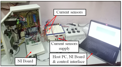
Experimental tests were performed in order to show the performance and reliability of the prototype equipped with the proposed CMSS. The tests devote more opportunities to analysis the behavior of the overall system under different conditions. The following experimental tests were performed: (i) start-up procedure; (ii) frequency controller; (iii) management system; (iv) normal stop procedure; (v) ES. A National Instruments (NI) board connected to a personnel computer is used in order to record different physical PHPP parameters and command laws. Figure 6 presents the proposed system with the NI board. The recorded data is focused on different command signals of limiting switches, buttons, departures, lights, security and different departure currents. The acquisition data devotes more opportunities to explain well the following scenario tests.
Figure 6. CMSS prototype and the NI board
4.1 Start-up procedure
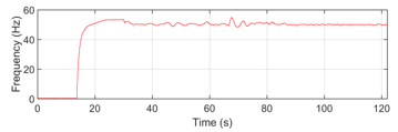
Figures 7, 8 and 9 show an experimental test during the start-up procedure using the controller and management systems. First, it is necessary to supply all electrical components and check the initial conditions that characterize a normal run of the PHPP: Three departures are disconnected and the turbine’s gate is at the minimum position. As soon as the operator presses the run button (Figure 8(a)), the proposed system immediately turns on both the GL (Figure 8(d)) and OL (Figure 8(e)). This represents an order from the operator to start opening the turbine’s gate until it reaches its maximum position (Figure 8(c)). At the same time, the LFC starts also to dissipate the produced power on the BL in order to keep the frequency around its nominal value (50 Hz) (during this phase none of the mini-grid departure is supplied). The turbine’s gate reaches its maximum position means that the produced power reaches its nominal value (200 W). The system turns off the OL (Figure 8(e)) and starts to connect the three departures (Figure 8(b), Figure 8(c) and Figure 8(d)) one by one. The connection of the last departure (Figure 8(d)) signifies that the start-up procedure is finished and the electricity is available for the local communities. According to the Figure 9(a), the security system supervises continuously the start-up procedure in order to avoid any failure of the plant.
Figure 7. Frequency evolution during start-up procedure versus time
Figure 8. Different command signals from the master device during PHPP start-up procedure. (a) Command signal of the R/S button (Run/Stop-cmd), (b) command signal of the Gmin (Gate-min), (c) command signal of the Gmax, (d) command signal of the GL (GL-cmd). (e) command signal of the OL (OL-cmd)
Figure 9. Different command signals from master device during PHPP start-up procedure. (a) Command signal of security relay (Security-cmd), (b) command signal of departure A (Dep A-cmd), (c) command signal of departure B (Dep B-cmd), (d) command signal of departure C (Dep C-cmd)
These obtained behavior results are completely normal by comparing these results with recent research publication [6]. According to the paper [6] and our obtained result, the frequency evolution versus behavior, during start-up procedure is similar. It’s concluded that the proposed system is able to realize a good PHPP start-up procedure.
4.2 Frequency controller
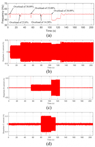
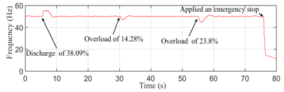
Through the Figure 10, the role of the controller system to maintain the frequency stable, when load variations occur, is clearly shown. Even with a load variation of one third of the produced power, the controller guarantees good frequency evolution. The controller could reject the electrical consumption perturbations’ effect. The proposed controller guarantee generated electric power of good quality, even with different load variations, as presented in Figure 8. As can be clearly seen that the controller stabilizes the frequency and current characteristics on a short time. This confirms the reliability of the controller system. On the other hand, the obtained waveform of the different departures’ currents could be used as a proof for different load variations occurred in the three departures. The obtained frequency curve, illustrated in Figure 10(a), when applying overloads and discharges, has a high accordance behavior with recent research publications [5, 6, 10, 31].
Figure 10. Experimental waveforms with application of different load variations. (a) Frequency waveform versus time, (b) current waveform of the departure A versus time, (c) current waveform of the departure B versus time, (d) current waveform of the departure C versus time
4.3 Management system
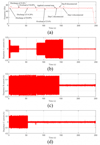
The proposed management system could prove its reliability through a simple scenario test. The test supposes the consumers use all the produced power i.e. there is no dissipated power in BL. After that, the consumers need more power for their activities. In this case, the consumed power becomes higher than the PHPP power, the frequency drops down automatically and the frequency controller wouldn’t be able to maintain 50Hz. Thus, after few seconds, the management system disconnects the lowest priority departure (departure C) (See Figure 12(c)). We suppose in this test that disconnecting departure C is not enough to get 50Hz again. Thus, disconnecting the departure B is necessary. It can be seen from Figure 12 (b) that the departure B was disconnected at 125 sec, which has allowed to get the frequency back to the standard value (50Hz).
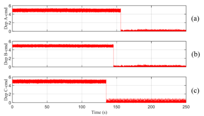
After one hour, the system tries to connect the disconnected departures (for experimental test, the authors took 1 min instead of one hour). The timing is chosen to guarantee some quality services for the local consumers. The current waveforms of different departures are presented in Figures 11(b), 11(c) and 11(d). These waveforms are used to effectively show the loads variation of each departure. As seen in the Figure 12(a), the management system takes into consideration the highest priority of the departure A which could be used to supply the off-grid site’s hospital. The obtained results, shown in Figures 11 and 12, provide PHPP performance that supports the useful of the proposed management system.
Figure 11. PHPP performance during management of the three departures. (a) Frequency response versus time, (b) absorbed current of the departure A versus time, (c) Absorbed current of the departure B versus time, (d) Absorbed current of the departure A versus time
Figure 12. Different command signals of the three departures during management procedure. (a) Command signal of departure A, (b) command signal of departure B, (c) command signal of departure C
According to the paper [6], the obtained result behavior of the frequency is normal. It’s concluded that the developed management system can guarantee a sustainable service for local communities with any human intervention is spite of different dangerous cases could affect the normal operation of the PHPP.
4.4 Normal stop procedure
During a usual operation of the plant, the operator decides to make a normal stop. The management has an artificial intelligence to know the departure status. The flexibility allows to the management system to begin the disconnection process from the lowest priority departure.
Figure 13. PHPP performance during a normal stop procedure. (a) Frequency response versus time, (b) Absorbed current of the departure A versus time, (c) absorbed current of the departure B versus time, (d) absorbed current of the departure A versus time
Figure 13 shows normal stop procedure, the frequency evolution and different consumed currents from the departures. It can be remarked that the system makes a success to stop the plant without any staff intervention. The Figure 14 illustrates different command signals of the departures.
The analysis of the obtained results, illustrated in Figures 13 and 14 and the recent published results in the paper [6], the obtained behavior is completely normal.
Figure 14. Different command signals of the three departures during a PHPP normal stop procedure. (a) Command signal of departure A, (b) command signal of departure B. (c) command signal of departure C
4.5 Emergency stop
The validation of the ES could perform by the following simple scenario test: during normal PHPP operation, the consumers use all the produced power, then, the BL is disconnected accidently (appearance of a BL fault). Thus, the consumers disconnect a load of 38.09% of the nominal power. Immediately, the frequency reaches a high amplitude value and the controller system wouldn’t be able to establish the frequency since we suppose that there is a BL fault. Therefore, an ES is necessary and the system lets a message on LCD and keeping a RL-ON. These actions indicate to the operator that the plant stopped with an ES procedure. Figure 15 shows the frequency evolution for the experimental test during an automatic ES. Figure 16 illustrates the two actions (LCD message and the RL). As we can see from these Figures, the proposed CMSS could successfully performed an ES at time 110 sec when the frequency couldn’t be regulated at 50Hz. The LCD display the message “Emergency stop” in order to notify the reason for which the plant was stopped.
A manual ES is shown in Figure 17. During a normal PHPP operation, the operator if he observes an unusual operation of the system, such as the degradation of the hydraulic system or other reasons. The operator should immediately decide to make a manual ES using an ES button.
According the proposed scenarios, including an automatic ES and manual ES, and the recent research published [6], it’s clear that the proposed security system is reliable to keep the plant safe all the time without any intervention.
Figure 15. Frequency evolution during an automatic ES
Figure 16. LCD message and keeping RL-ON after an ES
Figure 17. Frequency evolution during a manual ES
The goal of this study is to realize a system for PHPP at low-cost, especially developing countries with limited resources. The budget for the proposed system is described in Table 2. The prototype cost, including all system’s devices without frequency sensor, was approximately 266 $. The price of each device is collected based on websites (www.rs.com, www.digikey.com, www.lelectricien.net), where the price is usually higher compared to the local market price. The price could be reduced when considering the mass produced. Therefore, the proposed system could be considered a competitive system compared to the existing industrial system that uses PLC device [13].
Table 2. Budget for the low-cost CMSS of PHPP, including all the proposed system’s components without the frequency sensor
|
Components |
Quantity |
Price ($) |
|
Arduino MEGA board |
01 |
34 |
|
Arduino NANO board |
02 |
44 |
|
PCF8591 |
01 |
2.76 |
|
Electromagnetic relay |
07 |
22.722 |
|
Limiting switch |
02 |
1.4 |
|
Keypad |
01 |
64.678 |
|
GDM1604B LCD |
01 |
14.97 |
|
Lights |
03 |
8.7 |
|
CNY17Y |
07 |
3.57 |
|
LM324N, BC 108, 7812, 7805, diodes, resistors |
|
19.79 |
|
Box, specific adaptation connectors, wire, PCB |
|
50.24 |
|
Total price without frequency sensor and battery |
|
266.83 |
The proposed system current consumption was approximately 700 mA, when the system uses all its actuators. The current consumption was variable during normal PHPP operation. The variation depends directly on the PHPP procedures. For that reason, the current consumption could vary between 200 mA and 700 mA.
In this paper, a CMSS that ensure an autonomous operation of single-phase PHPP was proposed. The proposed system includes three sub-systems, the controller system, the management system and the security system. The controller system keeps the frequency around its nominal value when applying different load discharges or overloads on the mini-load grid. The management system gives more chances to manage well the produced power for maintaining local sustainable electrical services to the local communities. Besides, the security system is considered the highest priority hierarchy that helps to protect all mechanical and electrical components. The hardware design of the system is easy-to-obtained and software is free, making it affordable to any research and academic structure unit. Some experimental tests, illustrated in results section, were presented to explore its reliability. Besides, the proposed system can also be adapted to different hydroelectric power plants by applying simple adaptations.
The proposed CMSS devotes for promising horizons, both educational and research fields. Among these, the proposition of advanced embedded controller systems using fuzzy logic and benefits the non-linear character of the plant. The system gives also more opportunities to improve the management system by adding new management strategies.
PHPP: Pico-hydroelectric power plant.
CMSS: Controller, management and security system.
PLC: Programmable logic controller.
I/O: Inputs/outputs.
PID: Proportional integral derivative.
IDE: Integrated development environment.
PV: Photovoltaic.
LED: Light-emitting diode.
LFC: Load-frequency controller.
ES: Emergency stop.
LCD: Liquid-crystal display.
HMI: Human-machine interaction.
GL: Green light.
RL: Red light.
OL: Orange light.
PCB: Printed circuit board.
APC: Analog power controller.
BL: Ballast load.
SFC: Speed-flow controller.
ISE: Integral of the squared error.
DAC: Digital-analog converter.
DA: Digital-analog.
I2C: Inter-integrated circuit.
AD: Analog-digital.
VDC: Voltage direct current.
Gmin: Turbine gate position at the minimum.
Gmax: Turbine gate position at the maximum.
NI: National instruments.
Run/Stop-cmd: Input signal of run/stop button.
GATE-min: Input signal of Gmin.
GATE-max: Input signal of Gmax.
GL-cmd: Command signal of GL.
OL-cmd: Command signal of OL.
Dep A-cmd: Command signal of departure A.
Dep B-cmd: Command signal of departure B.
Dep C-cmd: Command signal of departure C.
Security-cmd: Command signal of security system.
[1] Wang, N., Chang, Y.C. (2014). The evolution of low-carbon development strategies in China. Energy, 68: 61-70. https://doi.org/10.1016/j.energy.2014.01.060
[2] Aydin, G., Jang, D.H., Topal, E. (2016). Energy consumption modeling using artificial neural networks: The case of world’s highest consumers. Energy Sources Part B Economics Planning Policy, 11(3): 212-9. https://doi.org/10.1080/15567249.2015.1075086
[3] Jin, J., Zhou, P., Zhang, M., Yu, X,. Din, H. (2018). Balancing low-carbon power dispatching strategy for wind power integrated system. Energy, 149: 914-924. https://doi.org/10.1016/j.energy.2018.02.103
[4] El hamdaouy, A., Salhi, I., Belattar, A., Doubabi, S. (2017). Takagi-Sugeno fuzzy modeling for three-phase micro hydropower plant prototype. International Journal of Hydrogen Energy, 42: 17782-17792. https://doi.org/10.1016/j.ijhydene.2017.02.167
[5] Salhi, I., Doubabi, S., Essounbouli, N., Hamzaoui, A. (2014). Frequency regulation for large load variations on micro-hydro power plants with real-time implementation. Electrical Power and Energy Systems, 60: 6–13. https://doi.org/10.1016/j.ijepes.2014.02.029
[6] El hamdaouy, A., Salhi, I., Doubabi, S., Chennani, M. (2017). Study and design of a pico-hydropower plant for academic education and research use. Int. J. Continuing Engineering Education and Life-Long Learning, 27(4): 303–317. https://doi.org/10.1504/IJCEELL.2017.087135
[7] Sun, Y.G., Xu, J.Q., Chen, C., Lin, G.B. (2019). Fuzzy H∞ robust control for magnetic levitation system of maglev vehicles based on T-S fuzzy model: Design and experiments. Journal of Intelligent & Fuzzy Systems, 36(2): 911-922. https://doi.org/10.3233/JIFS-169868
[8] Sun, Y.G., Xu, J.Q., Qiang, H.Y., Chen, C., Lin, G.B. (2019). Adaptive sliding mode control of maglev system based on RBF neural network minimum parameter learning method. Measurement, 141: 217-226. https://doi.org/10.1016/j.measurement.2019.03.006
[9] Sun, Y.G., Li, W.L., Xu, J.Q., Qiang, H.Y., Chen, C. (2017). Nonlinear dynamic modeling and fuzzy sliding‑mode controlling of electromagnetic levitation system of low‑speed maglev train. Journal of Vibroengineering, 19(1): 328‑342. https://doi.org/10.21595/jve.2017.17499
[10] Ozdemir, M.T., Orhan, A. (2015). A new approach to the development of a nonlinear model for micro-Pelton turbines. Turk J Elec Eng & Comp Sci, 23: 1272-1283. https://doi.org/10.3906/elk-1303-72
[11] Sahu, R.K., Panda, S., Rout, U.K., Sahoo, D.K. (2016). Teaching learning based optimization algorithm for automatic generation control of power system using 2-DOF PID controller. Electrical Power and Energy Systems, 77: 287-301. https://doi.org/10.1016/j.ijepes.2015.11.082
[12] Salhi, I., Doubabi, S., Essounbouli, N., Hamzaoui, A. (2010). Application of multi-model control with fuzzy switching to a micro hydro-electrical power plant. Renewable energy, 35: 2071-2079. https://doi.org/10.1016/j.renene.2010.02.008
[13] Fuentes, M., Vivar, M., Burgos, J.M., Aguilera, J., Vacas, J.A. (2014). Design of an accurate, low-cost autonomous data logger for PV system monitoring using Arduino™ that complies with IEC standards. Solar Energy Materials & Solar Cells, 130: 529-543. https://doi.org/10.1016/j.solmat.2014.08.008
[14] Teikari, P., Najjar, R.P., Malkki, H., Knoblauch, K., Dumortier, D., Gronfier, C., Cooper, H.M. (2012). An inexpensive Arduino-based LED stimulator system for vision research. Journal of Neuroscience Methods, 211: 227-236. https://doi.org/10.1016/j.jneumeth.2012.09.012
[15] Candelas, F.A., García, G.J., Puente, S., Pomares, J., Jara, C.A., Pérez, J., Mira, D., Torres, F. (2015). Experiences on using Arduino for laboratory experiments of Automatic Control and Robotics. IFAC-Papers On Line 48(29): 105–110. https://doi.org/10.1016/j.ifacol.2015.11.221
[16] Grassini, S., Corbellini, S., Parvis, M., Angelini, E., Zucchi, F. (2018). A simple Arduino-based EIS system for in situ corrosion monitoring of metallic works of art. Measurement, 114: 508-514. https://doi.org/10.1016/j.measurement.2016.07.014
[17] Ofosu, R.A., Kaberere, K.K., Nderu, J.N., Kamau, S.I. (2019). Design of BFA-optimezed fuzzy electronic load controller for micro hydro power plants. Energy for Sustainable Development, 51: 13-20. https://doi.org/10.1016/j.esd.2019.04.003
[18] Vovna, O.V., Laktionov, I.S., Dobrovolska, L.O., Kabanets, M.M., Lebediev, V.A. (2019). Evaluation of metrological characteristics of a computerized conductivity meter of irrigation solution based on the uncertainty theory. Journal Européen des Systèmes Automatisés, 52(4): 333-340. https://doi.org/10.18280/jesa.520401
[19] Wahyuadnyana, K.D., Gunawan, A.A.N., Paramarta, I.B.A. (2019). Remote control of room lights and coolers automation system SMS based. Journal Européen des Systèmes Automatisés, 52(4): 425-428. https://doi.org/10.18280/jesa.520413
[20] https://store.arduino.cc/arduino-mega-2560-rev3, accessed on Feb, 13, 2020.
[21] http://www.xmocular.com/Upload/CMpdf/GDM1604B-01011159259.pdf, accessed on Feb, 13, 2020.
[22] https://www.alldatasheet.com/view.jsp?Searchword=Cny17%20datasheet&gclid=EAIaIQobChMIsrvitbzP5wIVF-DtCh1Mzg_6EAAYASAAEgKG-_D_BwE, accessed on Feb, 13, 2020.
[23] https://ardetem-sfere.com/dip-605c-dgn-95ic/, accessed on Feb, 13, 2020.
[24] El Hamdaouy, A., Salhi, I., Belattar, A., Doubabi, S. (2016). Takagi-Sugeno fuzzy modeling for three-phase micro hydropower plant prototype with a new load-frequency regulation structure. Proceeding of 2016 IEEE, International Conference on Electrical Sciences and Technologies in Maghreb (CISTEM’16). https://doi.org/10.1109/CISTEM.2016.8066779
[25] Şerban, I., Marinescu, C. (2011). Aggregate load-frequency control of a wind-hydro autonomous microgrid. Renewable Energy, 36: 3345-3354. https://doi.org/10.1016/j.renene.2011.05.012
[26] El hamdaouy, A., Salhi, I., Belattar, A., Doubabi, S. (2016). Modeling a three-phase micro hydropower plant prototype using Takagi-Sugeno Fuzzy approach. proceedings of 2016 IEEE, 4th International Renewable and Sustainable Energy Conference (IRSEC’16), pp. 575-581. https://doi.org/10.1109/IRSEC.2016.7983880
[27] Qian, D.W., Tong, S.W., Liu, X.J. (2015). Load frequency control for micro hydro power plants by sliding mode and model order reduction. Automatica, 56(3): 318-330. https://doi.org/10.7305/automatika.2015.12.816
[28] Sanathanan, C.K. (1988). A frequency domain method for tuning hydro governors. IEEE Transactions on Energy Conversion, 3(1): 14-17. https://doi.org/10.1109/60.4193
[29] Orelind, G., Wozniak, L., Medanic, J., Whittemore, T. (1989). Optimal PID gain schedule for hydrogenerators-design and application. IEEE Transactions on Energy Conversion, 4(3): 300-307. https://doi.org/10.1109/60.43228
[30] Garrido, J., Zafra, A., Vázquez, F. (2009). Object oriented modelling and simulation of hydropower plants with run-of-river scheme: A new simulation tool. Simulation Modelling Practice and Theory, 17: 1748–1767. https://doi.org/10.1016/j.simpat.2009.08.007
[31] El hamdaouy, A., Salhi, I., Doubabi, S. (2019). Load frequency controller based on PI fuzzy self-tuning for a three-phase micro hydroelectric power plant. Soft Computing and Electrical Engineering, 1(2): 26-39.