Srinivasarao Gorantla| Raghavaiah Katuri*
OPEN ACCESS
In this paper, a different control scheme has been proposed in order to attain the precise control between battery and ultracapacitor (UC) of a hybrid energy storage system (HESS). An MFB controller is considered with four individual math function corresponding to the speed of the motor and treated as a universal controller. Thereafter MFB is integrated with a conventional/intelligent controller to attain the main objective of the paper. The considered MFB is join with conventional PI as well as ANN and comparative analysis is done between two controllers performance based on different time domain specifications. In order to know the performance of the specific controller entire circuit can be configured into four modes, and each mode of operation, the proposed controllers are implemented separately in MATLAB/Simulink. The solar panel is used here to charge the battery directly via control switch two, the battery charging and discharging conditions are controlled by the state of charge (SOC) as well as the output voltage level of a solar panel converter.
battery, ultracapacitor (UC), bidirectional converter (BDC), unidirectional converter, math function based (MFB) controller, proportional-integral (PI) controller, artificial neural network (ANN) controller, electric vehicles (EVs), solar power
Replacing of conventional IC engine vehicles is one of the alternative methods of reducing pollution content in the atmosphere which can be replaced IC engine based vehicles with HEVs/EVs. Base fuel supply to the EVs/HEVs during all road conditions, corresponding to the vehicle dynamics is the major challenge related to HEVs/EVs. Because the base fuel used to drive vehicle is not having a high power density of ability, which degrades the performance of the vehicle during transient periods. To overcome those obstacles base source is hybridized with an alternating source, this combination capable of delivering energy to the vehicle according to its dynamics.
The photovoltaic generator is used as a base source to drive electric train and battery can be used as an auxiliary source. The battery is connected at boost converter side on the other hand; PVG is connected at buck-boost converter side to encounter the load requirement [1]. The existed transportation system is one of the major causes to produce greenhouse gases during its successive operation. In order to reduce the pollution effect on the atmosphere, the conventional transportation system is replaced with HEVs/EVs, which are almost eco-friendly because these are driven by solar power [2]. Different types of dc-dc and dc-ac converters are used to supply power to the vehicle, which is connected, to common dc bus link. Here all type of converters is used to maintain the energy management between UC and fuel cell [3]. An adaptive rate limit controller is used to divide the energy between sources connected in EV as a source, which will enhance the major source lifetime [4]. Flywheel and battery are hybridized and implemented to propel the HEVs/EVs based on its requirement, from that two sources, the battery will act as a major source and on the other hand, flywheel acts as a minor source [5]. The fuzzy logic based controller is used for splitting energy between battery and UC which is used for transportation system applied to electric vehicles [6]. A real-time controller is designed and implemented to HESS powered vehicle for proper energy sharing between battery and UC. A rule-based controller implemented to the vehicle and compared with exited controller performances [7]. A real-time controller is with an optimized condition and applied to the vehicle for proper power splitting between energy sources present in HESS [8]. Especially for plug-in type electric vehicles, an algorithm-based controller is designed and applied to energy management system [9-10]. Portable UC based electric vehicle is designed, in which UC is used for stating EV in order to decrease the extra load on the base source [11].
Generally, the PV array is the combination of PV modules, which again a combination of a group of PV cells.
Figure 1. Practical PV cell circuit representation
Above circuit represents that practical PV cell, in which Rsh and Rse are shunt and series resistance. On the other hand, Iph is the photon current present in the circuit.
The photon current can be represented with
${{I}_{ph}}={}^{[{{I}_{scr}}+{{K}_{i}}(T-298)]*\lambda }/{}_{1000}$ (1)
Reverse saturation current of the module is given by
${{I}_{rs}}={}^{{{I}_{scr}}}/{}_{[\exp (q{{V}_{OC}}/{{N}_{S}}kAT)-1]}$ (2)
The saturation current of module is
${{I}_{0}}={{I}_{rs}}{{[\frac{T}{{{T}_{r}}}]}^{3}}\exp [\frac{q*{{E}_{go}}}{Bk}\left\{ \frac{1}{{{T}_{r}}}-\frac{1}{T} \right\}$ (3)
PV module total current is
${{I}_{PV}}={{N}_{P}}*{{I}_{0}}[\exp \{\frac{q*({{V}_{PV}}+{{I}_{PV}}{{R}_{S}})}{{{N}_{S}}AkT}\}-1]$ (4)
Complete system block diagram with proposed control strategy is represented in Figure 2 which includes a solar panel, battery, UC, UDC, BDC, and electric drive. In the entire block diagram, controller part is the main focused area, which is used to produce to the controlled switching signal to the UDC as well as BDC. The proposed control method is realized mainly with two different controllers, in that conventional/intelligent controller is used to generate the switching signal and the second one is MFB controller is used to regulating the switching pulses related to the speed of the motor. The output signals of two controllers can be compared in the presence of breaker, thereafter the controlled signal is given to the switches present in DC-DC converters.
Figure 2. Proposed scheme represented in block diagram
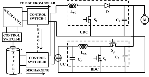
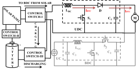
Figure 3 representing the Proposed scheme represented in block diagram, which includes different switches named as S1, S2, and S3. The BDC contain two switches S2, S3 to perform either boost or buck operation and UDC having only one switch S1 to perform boost operation. Three control switches are connected at different places among battery, solar panel, and converter. Here solar power is used to charge the battery depending upon the temperature availability and irradiance value. If battery SOC shows hundred percentage then the solar output is directly associated to UDC through control switch one.
Figure 3. Model representation with main converters and PV
To achieve the proposed control objective two different controllers are integrated and implemented to the main circuit. From those two controllers, MFB controller is the first one and acted as a universal controller and the second one is the conventional/intelligent controller.
4.1 MFB controller
The main intention of the considered MFB controller is to regulate the switching signals of unidirectional (UDC) and bidirectional converter (BDC) as per vehicle requirement. This has been considered with four individual math functions according to the speed of the motor. Each math function representing a certain range of speed of an electric motor. The MFB controller develops four outputs by taking speed as input, outputs of MFB can be represented as U1, U2, U3, and U4. This output sometimes is in ON condition sometimes is in OFF condition, which is based on the sensed input value by the MFB controller.
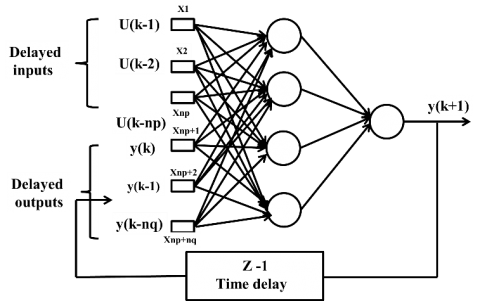
4.2 Artificial neural network controller (ANN)
In this work, the ANN controller is used to developing the switching signal to the switches present in DC-DC converters. Here two converters BDC, as well as UDC both, are trained using a neural network. Finally, the required output is found according to the load requirement.
Figure 4. General model representation of an artificial neural network
4.3 PI Controller
The required of a PI controller is find from error value, which is obtained from a difference between setpoint (SP), and process variable (PV) is given as
e(t)=SP-PV (5)
Figure 5. Conventional representation of PI controller
And the controller final output value is found from bellow relation
$u(t)={{u}_{bias}}+{{K}_{c}}e(t)+\frac{Kc}{{{\tau }_{i}}}\int\limits_{0}^{t}{e(t)}dt$ (6)
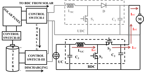
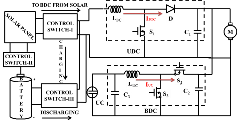
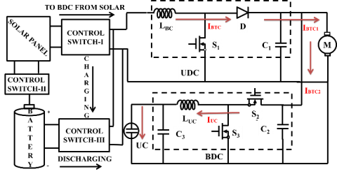
Figures 6, 7, 8 and 9 are representing the main circuit working condition at different load conditions. Figure 6 is associated to heavy load condition on the electric motor, which shows BDC operation under boost mode. This indicates that UC only supplies the whole power demanded by the motor. From Figure 7, it is clear that UDC and BDC both collectively gives the required power to the motor, which shows that UC supporting the base source. Figure 8 is associated to the rated load applied, due to which UDC only in operation and battery can supply entire power to the load. Finally, Figure 9 shows the no load on the motor, in this state BDC (buck) and UDC (boost) both are in operation [12].
Figure 6. Model representation with main converters and PV, mode one
Figure 7. Model representation with main converters and PV, mode two
Figure 8. Model representation with main converters and PV, mode three
Figure 9. Model representation with main converters and PV, mode four
How the controlled pulse signal is developing corresponding to the speed of the motor by the designed MBF with PI/ANN controller is representing in a simple way with Figure 10. Total four modes are considered to know the performance of the electric vehicle with different load conditions. Each mode is designed corresponding to the speed and applied the load to the electric motor. Four modes operation related to a speed of the motor can be represented as
Figure 10. Flowchart of the proposed control strategy
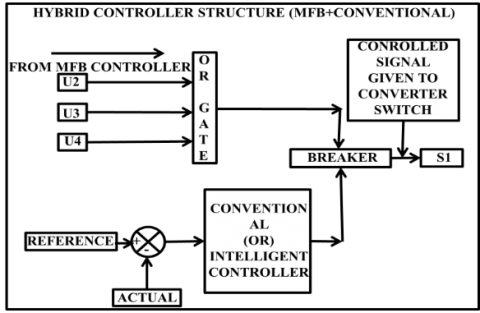
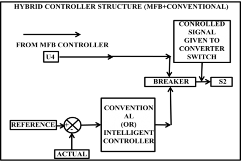
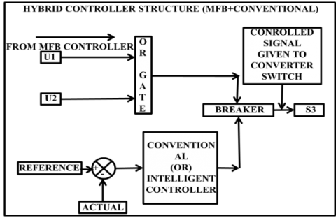
Figures 11, 12 and 13 are representing the overall control structure, which includes how the controlled switching signals are producing to specific switch in UDC and BDC. Here the combination of MFB with PI/ANN can be producing the controlling signal to switches, which is purely, related to the speed of the motor.
The controlled pulse signals will generate to particular switch as follows by the designed hybrid controller
For switch S1: The controlled switching signals are given to S1 if the output signal of MFB controller is either U2, U3, U4.
For switch S2: The output signals of the MFB controller will generate U4, at this particular condition the controlled switching signals are given to switch S2.
For switch S3: The MFB controller output is U1, U2 then the controlled switching signals are provided to the switch S3.
Figure 11. Controlled switching signals produced structure to switch ONE
Figure 12. Controlled switching signals produced structure to switch TWO
Figure 13. Controlled switching signals produced structure to switch THREE
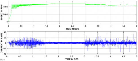
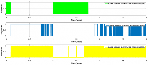
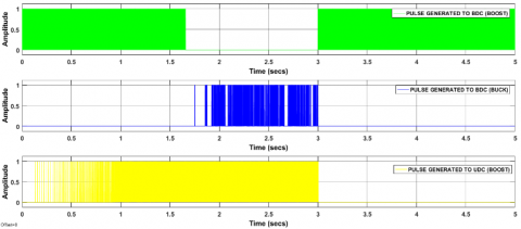
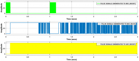
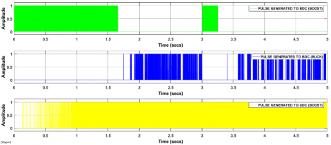
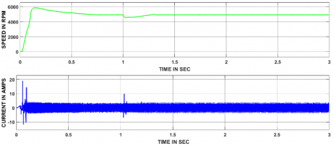
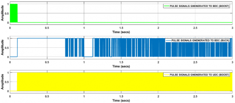
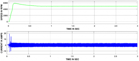
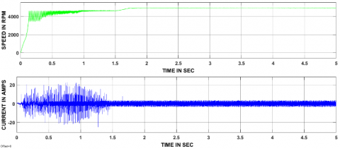
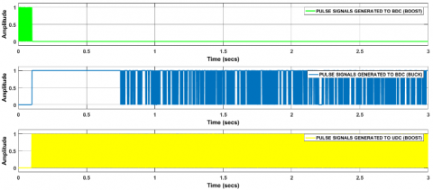
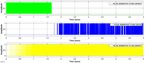
In this section, four modes simulation results are plotted. Figures 14, 18, 22 and 26 are the speed and current responses of related to MFB with ANN controller. In the same way figures 15, 19, 23 and 27 are the speed and current responses corresponding to MFB with PI controller. Figures 16, 20, 24 and 28 are representing the controlled switching pulses produced to BDC and UDC by MFB with ANN controller. In the same way figures 17, 21, 25 and 29 are the controlled switching pulses produced by the MFB with PI.
7.1 Mode-I results
Figure 14. Outcomes of the motor corresponding to MBF with ANN controller during mode one operation
Figure 15. Outcomes of the motor corresponding to MBF with PI controller during mode one operation
Figure 16 Controlled switching signals produced to UDC and BDC by the MBF with ANN controller during mode one operation
Figure 17 Controlled switching signals produced to UDC and BDC by the MBF with PI controller during mode one operation
7.2 Mode-II results
Figure 18. Outcomes of the motor corresponding to MBF with ANN controller during mode two operation
Figure 19. Outcomes of the motor corresponding to MBF with PI controller during mode two operation
Figure 20. Controlled switching signals produced to UDC and BDC by the MBF with ANN controller during mode two operation
Figure 21. Controlled switching signals produced to UDC and BDC by the MBF with PI controller during mode two operation
7.3 Mode-III results
Figure 22. Outcomes of the motor corresponding to MBF with ANN controller during mode three operation
Figure 23. Outcomes of the motor corresponding to MBF with PI controller during mode three operation
Figure 24. Controlled switching signals produced to UDC and BDC by the MBF with ANN controller during mode three operation
Figure 25. Controlled switching signals produced to UDC and BDC by the MBF with PI controller during mode three operation
7.4 Mode-IV results
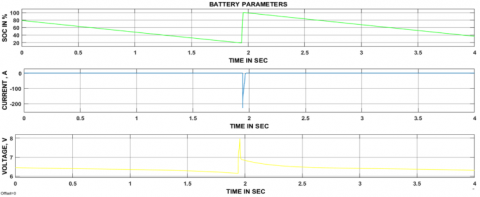
The battery charging and discharging periods are controlled based on the SOC of the battery. Here battery will charge whenever its SOC range is less than 20% on the other hand discharges the equal energy to the vehicle. From above Figure 30, it is clear that whenever the battery SOC decreased by less than 20% then battery gets charged from the solar energy; during that period battery current shows a negative value. In the same battery, current shows positive value during discharging periods.
Figure 26. Outcomes of the motor corresponding to MBF with ANN controller during mode four operation
Figure 27. Outcomes of the motor corresponding to MBF with PI controller during mode four operation
Figure 28. Controlled switching signals produced to UDC and BDC by the MBF with ANN controller during mode four operation
Figure 29. Controlled switching signals produced to UDC and BDC by the MBF with PI controller during mode four operation
7.5 Battery charging and discharging periods with parameters
Figure 30. Various paprmeters of the battery
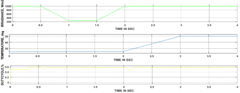
7.6 Solar panel input parameters with variations
Figure 31 shows that the duty cycle applied to the converter connected between the battery and solar panel, solar panel input irradiance, and temperature. In this work, power is obtained corresponding to different irradiance value as well as temperatures. The duty cycle provides to the converter is also varied based on the irradiance and temperature values. The temperature value changed from 250c to 500c and changed the irradiance values from 1000 w/sm to 300 w/sm, obtained power at different voltage levels.
Table 1 representing that the different time periods taken by the two controllers to attain steady state after applying the load to the motor during different modes of operation. During mode one, two and three MFB with ANN controller has taken 0.75 sec, 0.25 sec and 0.1 sec time to reach steady state. On the other hand, MFB with PI controller case in mode one operation, the motor does not reach the steady state within a given time period, wherein mode two and three cases 0.5 sec, 0.15 sec time taken to attain stable state. In both the controller's case, during mode four operation no load is applied. During starting of the motor, in case of MFB with ANN controller has taken 0.15 sec to attain a stable state whereas MFB with PI controller has taken 1.6 sec time.
Figure 31. Various parameters of PV module
Table 1. Performance analysis between two controllers after applying load on the electric motor
|
Controller type |
The steady-state time corresponding to different loads (sec) |
|||
|
Mode-I |
Mode-II |
Mode-III |
Mode-IV |
|
|
MFB with ANN |
0.75 |
0.25 |
0.1 |
No load applied |
|
MFB with PI |
Not setelled |
0.5 |
0.15 |
No load applied |
|
S.No |
Type of mode |
State of UDC |
State of BDC |
Power flow direction |
|
1 |
Mode-I |
Off |
Boost |
UC $\to$ motor |
|
2 |
Mode-II |
Boost |
Boost |
Battery + UC $\to$ motor |
|
3 |
Mode-III |
Boost |
Off |
Battery $\to$ motor |
|
4 |
Mode-IV |
Boost |
Buck |
Battery $\to$ UC+motor |
Table 3. Performance analysis of controllers based on time domain specifications
|
Controller type |
Delay time (sec) |
Rise time (sec) |
Peak time (sec) |
Settling time (sec) |
Maximum peak overshoot (%) |
|
MFB with ANN |
0.05 |
0.08 |
0.1 |
0.6 |
12 |
|
MFB with PI |
0.25 |
1.6 |
1.7 |
1.8 |
7 |
The solar-powered electric vehicle is implemented with a new control strategy approach. The designed MFB controller is implemented with ANN and PI and obtain the satisfactory results from both the controllers. Among all the controllers, MFB played an important role during a transition of energy source from one to another related to the speed of the motor. Other controllers ANN and PI are used to produce the switching pulses to switches in UDC and BDC. In the proposed control strategy MFB controller controlled the switching signals developed by conventional/intelligent controller related to the speed of the motor. Finally, controlled pulses are developed and given to the switches in BDC and UDC. Comparative analysis has been done between two controllers based on different time domain specifications and all are tabulated in the conclusion section.
Table 4. Performance analysis between controllers with and without load condition
|
Controller type |
Steady-state time at starting (sec) |
Steady-state time at rated load (sec) |
|
MFB with ANN |
0.15 |
0.1 |
|
MFB with PI |
1.6 |
0.15 |
[1] Lovatt HC, Ramsden VS, Mecrow BC. (1998). Design of an in-wheel motor for a solar-powered electric vehicle. IEE Proceedings-electric Power Applications 145(5): 402-408. https://doi.org/10.1109/SGBC.2016.7936074
[2] Bendjedia B, Hadjadj A, Benhouia A, Temmir M. (2015). Energy management and control of a solar electric vehicle. In Electrical Engineering (ICEE), 2015 4th International Conference on IEEE, pp. 1-5. https://doi.org/10.1109/INTEE.2015.7416702
[3] Tani A, Camara MB, Dakyo B, Azzouz Y. (2013). DC/DC and DC/AC converters control for hybrid electric vehicles energy management-ultracapacitors and fuel cell. IEEE Transactions on Industrial Informatics 9(2): 686-696. https://doi.org/ 10.1109/TII.2012.2225632
[4] Wu D, Todd R, Forsyth AJ. (2015). Adaptive rate-limit control for energy storage systems. IEEE Transactions on Industrial Electronics 62(7): 4231-4240. https://doi.org/10.1109/TIE.2014.2385043
[5] Lustenader EL, Guess RH, Richter E, Turnbull FG. (1977). Development of a hybrid flywheel/battery drive system for electric vehicle applications. IEEE Transactions on Vehicular Technology 26(2): 135-143. https://doi.org/10.1109/T-VT.1977.23670
[6] Yin H, Zhou W, Li M, Ma C, Zhao C. (2016). An adaptive fuzzy logic-based energy management strategy on battery/ultracapacitor hybrid electric vehicles. IEEE Transactions on Transportation Electrification 2(3): 300-311. https://doi.org/10.1109/TTE.2016.2552721
[7] Shen J, Khaligh A. (2016). Design and real-time controller implementation for a battery-ultracapacitor hybrid energy storage system. IEEE Transactions on Industrial Informatics 12(5): 1910-1918. https://doi.org/10.1109/TII.2016.2575798
[8] Wu J, Ruan J, Zhang N, Walker PD. (2018). An optimized real-time energy management strategy for the power-split hybrid electric vehicles. IEEE Transactions on Control Systems Technology 1-9. https://doi.org/10.1109/TCST.2018.2796551
[9] Zhang J, Shen T. (2015). Energy management strategy design for plug-in hybrid electric vehicles with continuation/GMRES algorithm. In 2015 European Control Conference (ECC), pp. 2964-2969. https://doi.org/10.1109/ECC.2015.7330988
[10] Horrein L, Bouscayrol A, Cheng Y, Dumand C. (2015). Hybrid energy management Strategy for hybrid electric vehicle. In 2015 IEEE Vehicle Power and Propulsion Conference (VPPC), pp. 1-6. https://doi.org/10.1109/VPPC.2015.7352963
[11] Averbukh M, Lineykin S, Kuperman A. (2015). Portable ultracapacitor-based power source for emergency starting of internal combustion engines. IEEE Transactions on Power Electronics 30(8): 4283-4290. https://doi.org/10.1109/TPEL.2014.2355422
[12] Xiang C, Wang Y, Hu S, Wang W. (2014). A new topology and control strategy for a hybrid battery-ultracapacitor energy storage system. Energies 7(5): 2874-2896. https://doi.org/10.3390/en7052874