Abderrahmane Boudribila*![]() | Abdelouahed Tajer
| Abdelouahed Tajer![]() | Zakaria Boulghasoul
| Zakaria Boulghasoul![]()
© 2025 The authors. This article is published by IIETA and is licensed under the CC BY 4.0 license (http://creativecommons.org/licenses/by/4.0/).
OPEN ACCESS
Developing control programs for manufacturing systems is time-consuming and requires expert control designers. While manual programming is common, it becomes complex as systems grow, leading to long development times, frequent errors, and difficult maintenance. To address these issues, researchers have introduced formal methods like Supervisory Control Theory (SCT) and model checking to improve precision and verification. Although these are some of the most advanced approaches, they are difficult to use in practice because they are time-consuming, require high mathematical expertise, and face scalability problems such as combinatorial explosion in large systems. This study aims to overcome these limitations by presenting an AI-based system that automatically generates programmable logic controller (PLC) code from natural language requirement specifications. The approach uses AutoFactory, a dataset of annotated specifications, and fine-tunes two Bidirectional Encoder Representations from Transformers (BERT)-based models to extract actuators, pre-actuators, and sensors before generating International Electrotechnical Commission (IEC) 61131‑3 Structured Text (ST) code. BERT‑Base achieved an F1 score of 0.9711, showing reliable component extraction. The study proves that transformer models can accurately detect control components and initiate logic generation. These results confirm that AI can assist and augment control designers by automating extraction and initial coding. Future work will complete the pipeline to deliver verified IEC 61131‑3 code ready for industrial deployment.
code generation, IEC 61131-3, industrial automation, large language models (LLMs), manufacturing systems, named entity recognition (NER), natural language processing (NLP), programmable logic controllers (PLCs)
Manufacturing systems have changed over time as new technologies have been introduced. The First Industrial Revolution used steam power to operate machines [1]. The Second added electricity and allowed for mass production [2]. The Third brought automation with the help of computers [3]. Today, in the Fourth Industrial Revolution, known as Industry 4.0, machines are connected to computers and networks [4]. These systems are called Cyber-Physical Manufacturing Systems. They combine physical equipment with sensors, controllers, and software. This allows for real-time monitoring and control of production [5]. These changes have made manufacturing more efficient and flexible [6]. However, they have also increased the complexity of control. Writing control programs for such systems is now more difficult. It requires precise, reliable, and fast solutions that can handle complex and dynamic processes [7, 8].
As manufacturing systems have become more complex, the task of creating reliable control programs has become more demanding [9, 10]. In many cases, engineers still rely on heuristic methods to perform this task. This approach is based on the expert’s intuition, experience, and manual effort [11, 12]. The process begins with writing a requirement specification that describes the expected behavior of the system. Based on this specification, the expert designs a control program using their knowledge of the system. The program is then tested in a simulator to check if it behaves as expected. If the simulation reveals errors, the expert must go back, modify the program, and test it again. Once the simulation confirms that the program is correct, the code is transferred to the programmable logic controller. Although this method is simple and widely used in practice, it is slow, difficult to maintain, and prone to human error. Each update requires repeating the same steps, which makes the approach inefficient, especially for systems that change frequently or involve many components.
To address the limitations of heuristic methods, some researchers and engineers use formal methods to design control programs. Unlike heuristic approaches, which rely on intuition and manual programming, formal methods are based on mathematical models and systematic reasoning [13]. In this approach [11], the expert begins by identifying the components of the system and defining the constraints. These constraints describe both the desired actions and the conditions that must be avoided. The expert builds two separate models: one for the global behavior of the system and another for the constraints. These models are then combined to produce a single formal representation of the control logic. Techniques such as Supervisory Control Theory and model checking are commonly used at this stage. The formal model is then verified to ensure that it satisfies all requirements. If errors are found, it must be corrected and verified again. Once validated, the model is used to generate the control program that will be transferred to the PLC. Although formal methods improve precision and reduce ambiguity, they require strong mathematical knowledge and significant development time. As a result, they are difficult to apply in industrial settings, especially when the system is large or complex [14, 15].
In this work, we present a first step toward a new vision: enabling computers to understand manufacturing requirements written in natural language and generate control programs automatically. Our goal is to give computers the ability to identify key components such as actuators, pre-actuators, and sensors from a written specification. We aim to use the speed, consistency, and processing power of computers to reduce the time and effort needed for manual programming. This vision supports the idea of fully automating the code generation process, where the user only needs to describe the system’s behavior in simple terms. The computer will then extract the necessary information and generate the control logic without requiring expert intervention. Our pilot study is focused on building the foundation for this approach by training models that can extract key components from manufacturing specifications.
After identifying the components of the system, the next step is to generate the control logic for each one. In our approach, each detected component is linked to a predefined code function that describes its behavior. These functions are stored in a library and are called when the corresponding component is found in the specification. This method makes the system modular and easy to scale. It follows a divide-and-conquer logic, where the overall control program is built by combining the code of each part. This approach helps reduce development time and improves code structure and consistency. The rest of this paper is organized as follows. Section 2 presents related work. Section 3 explains the methodology, including dataset creation, model fine-tuning, and code generation. Section 4 discusses the results. Section 5 concludes the paper and outlines future work, highlighting how this dataset and tool can support researchers in automating code generation for manufacturing systems.
Control program development in manufacturing has traditionally followed two main approaches: heuristic methods and formal methods. Both have been used extensively in industry and academia. Each offers specific advantages but also presents important limitations. To better understand the motivations behind our proposed AI-based system, this section reviews the key principles and challenges of both methods. First, we describe the heuristic approach, which is based on the expert’s manual experience. Then, we present formal methods, which use mathematical modeling to ensure system correctness.
2.1 Heuristic methods
Heuristic methods refer to the traditional way of designing control programs based on the personal knowledge, intuition, and experience of the engineer. This approach does not rely on formal models or systematic reasoning. Instead, the expert interprets the system requirements and translates them into control logic manually. Heuristic methods are widely used in industrial environments because they are flexible and easy to apply in simple systems. They allow engineers to design solutions quickly when the system is small and well understood. However, as system complexity increases, relying only on intuition becomes more difficult and less reliable.
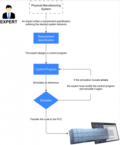
While heuristic methods are common in industrial settings, the process they follow is manual and iterative. It begins with the expert writing an informal requirement specification that describes the expected behavior of the system. Based on this description, the expert manually creates a control program using their experience and domain knowledge. The program is then tested through simulation to check whether it behaves as intended. If the simulation reveals errors, the expert revises the program and repeats the test. This cycle continues until the logic is considered correct. Finally, the validated program is transferred to the programmable logic controller (PLC), which is often referred to as the brain of the manufacturing system. The PLC executes the control logic using standard programming languages defined by the IEC 61131-3 standard [16]. These include three graphical languages, Ladder Diagram (LD), Function Block Diagram (FBD), and Sequential Function Chart (SFC) and two textual languages Instruction List (IL) and Structured Text (ST). The overall heuristic workflow is illustrated in Figure 1.
Figure 1. Workflow for control program development using heuristic methods
Heuristic methods are often used in universities and in small systems where the number of components is limited. In these simple cases, the expert can understand the requirement easily and write the control logic without difficulty. However, when the system becomes more complex, this method reaches its limits. It becomes harder to understand the interactions between components. Writing and testing the program takes more time. Since the process is manual, it is also more likely to include errors. Another limitation is related to maintenance. When changes are needed, it is often difficult to modify the program correctly, especially if it was written by someone else. In addition, learning to program in this way takes time and requires experience. For these reasons, heuristic methods are not suitable for large and dynamic systems that need reliability, consistency, and fast updates. This limitation has led to the development of formal methods, which aim to improve control program design through structured modeling and verification.
2.2 Formal methods
Formal methods offer a clear and structured approach for designing control programs. They rely on mathematical models to precisely describe how a system should behave and the rules it must follow [17, 18]. These methods are particularly valuable when safety, correctness, and reliability are important. Unlike heuristic methods, which depend mainly on human experience, formal methods allow the control logic to be verified and tested before the system is implemented. This verification step helps reduce errors during operation and makes the system easier to maintain and update later.
The process begins with a requirement specification, a clear description of what the system is expected to achieve. From this specification, an expert identifies the system components and defines two important types of constraints. Liveness constraints specify outcomes that the system must eventually achieve, such as moving a robotic arm to a precise location. Safety constraints define conditions that the system must avoid, such as activating two conflicting actions simultaneously [17, 18]. Using this information, two formal models are created. The first model, called the behavior model, describes step-by-step how the system operates. The second model, called the constraint model, clearly defines all the liveness and safety constraints. Together, these models provide a complete and precise description of the system’s allowed behaviors.
These models are often represented using formal tools such as finite automata, Petri nets, or GRAFCET diagrams. From these representations, controllers are developed in two main stages. First, local controllers are created for each component individually, ensuring they comply with their own specific constraints. Next, the local controllers are combined with global constraints to form distributed controllers, which coordinate the entire system. This combination process is known as controller synthesis and is commonly performed using Supervisory Control Theory or similar techniques. The result is a robust control strategy that only allows the system to behave in ways permitted by the original specification.
After creating these distributed controllers, they undergo a verification step to confirm that all requirements are met under every possible scenario. For complex systems that involve timing or multiple processes running simultaneously, model checking is performed. Model checking uses specialized tools such as UPPAAL or SUPREMICA to systematically explore the system’s state space and detect any problems, including potential deadlocks or violations of safety and liveness constraints. If any issues are found, the constraints or models are revised, and the synthesis and verification steps are repeated until the controllers satisfy all requirements fully.
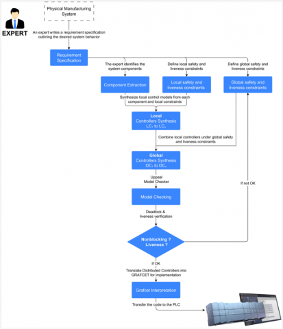
Once the verification step is successfully completed, the validated controllers are translated into Grafcet diagrams or other suitable programming formats. These diagrams can be directly deployed onto programmable logic controllers. This step ensures that the system operates exactly as designed, minimizing the need for further debugging during commissioning. The complete workflow for developing control programs using formal methods from initial specification through to final PLC implementation is shown in Figure 2.
Figure 2. Workflow for control program development using formal methods
Formal methods provide significant advantages for control system design. They enable the early detection of design errors, guarantee correctness by construction, and clearly trace the link between the original specifications and the implemented control code. They are particularly valuable for safety-critical systems, such as robotic work cells and transport automation, where unexpected behaviors could lead to serious hazards or costly operational failures.
However, formal methods also have limitations. Building accurate formal models is time-consuming and requires specialized skills in system modeling and formal logic. As the complexity of a system grows, the number of possible states that need to be checked increases rapidly. This rapid increase, known as combinatorial explosion, can make the verification process slow or even infeasible. Due to these challenges, formal methods are most commonly applied in academic research or in smaller industrial systems where the modeling effort is manageable.
In previous research, our team has successfully applied formal methods in practical settings, specifically for discrete-event modeling and controller synthesis using model-checking tools like SUPREMICA and UPPAAL [17, 18].
Although formal methods continue to offer a reliable approach for ensuring correctness, their complexity and scalability issues have limited wider adoption in industry. Recent research therefore explores combining formal methods with artificial intelligence techniques. AI-based approaches can reduce manual modeling effort, improve scalability, and increase flexibility in the control design process. The next section examines these promising new directions, focusing on how AI can automate key stages of control program development.
Control designers often face significant challenges when developing programs for Automated Production Systems. These systems consist of many components that must operate together in a coordinated way. This complexity often makes programming the entire system as a whole impractical. Designers commonly apply the divide and conquer principle: they break down the system into smaller units and control each component separately. However, applying this strategy requires identifying all components described in the requirement specification. While humans find this task relatively easy, it poses a significant challenge for computers, which necessitates advanced AI techniques.
To address this challenge, we propose a structured AI-based pipeline. This pipeline transforms a natural language requirement specification into a set of extracted components, each linked to its predefined control behavior. Our goal is to convert unstructured, human-written text into structured control logic elements for reuse and assembly. This approach reduces dependence on manual interpretation and forms the foundation for generating control programs. Figure 3 illustrates the pipeline’s structure. It presents the complete process, from requirement specifications through data preparation, model training, and component extraction. The pipeline then uses predefined logic blocks to define the control behavior of each identified element.
Figure 3. Overview of the proposed pipeline
Our work focuses on the early stages of this pipeline. It involves creating a labeled dataset, designing a custom annotation tool, and fine-tuning BERT models in both Base and Large configurations for component extraction. We evaluate these models for their ability to identify key control components such as sensors, actuators, and pre-actuators. We then use the extracted components to generate their associated control logic using predefined templates. This structure supports the long-term goal of automating control program generation from natural language input.
Developing this capability requires training data that accurately represents how control designers express system behavior and describe industrial components. To obtain such data, we first searched for existing datasets containing requirement specifications used in industrial automation. Our objective was to find examples that reflect the language and structure typically used in practice. However, most available datasets are designed for general-purpose language tasks, they do not include technical vocabulary or structured descriptions of industrial devices. To address this gap, we developed the AutoFactory dataset [19]. We specifically designed it to support training models that translate natural language specifications into control programs.
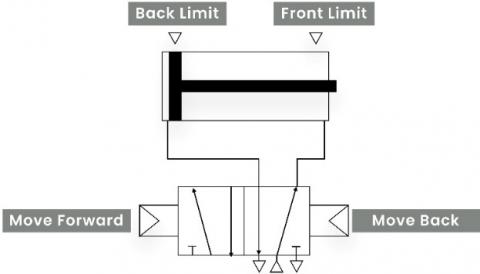
Manufacturing systems consist of multiple components that work together to perform specific tasks [20]. These components include actuators, pre-actuators, and sensors. Each component performs a distinct function, and its behavior must be clearly described in the requirement specification. To create training data suitable for this study, a collection of requirement specifications was manually written based on realistic industrial examples. Each specification was drafted by experienced control designers using structured language and precise technical terminology. One example describes a double-acting cylinder that extends until it reaches the front limit switch, then retracts to the back limit switch. A visual representation of this operation is shown in Figure 4.
Figure 4. Visual representation of a double-acting cylinder operation
After creating the initial set of requirement specifications, we expanded the dataset using large language models. Although each specification was written manually by a control designer, we observed that the same system behavior can be written in many different ways. In real projects, control designers often describe systems using their own wording and writing style. Some may write long descriptions, others may keep them short or omit certain details. Our goal is to give the control designer full freedom to write the requirement specification in English without having to follow strict rules. Even if the text contains small mistakes or inconsistent phrasing, the model should still be able to understand the meaning and generate the correct control logic. To prepare the system for this variability, we used language models to generate multiple versions of each specification with different writing styles.
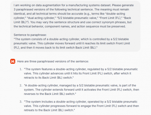
To generate these variations, we used three large language models [21]: ChatGPT Pro, Claude Pro, and Mistral Pro. These models were selected because they produce more accurate and consistent outputs than free versions. They are better at preserving the technical meaning of the original specification while allowing changes in sentence structure or vocabulary. For each requirement specification written by the control designer, we provided a prompt asking the models to produce multiple variations of the same description. This step is important because machines need to see many forms of the same idea in order to learn how to generalize. An example of the prompt and the generated variations is shown in Figure 5. Each version keeps the same system behavior but uses a different way of expressing it.
Figure 5. Prompt and example outputs generated by LLM
After generating the variations, we performed a cleaning step to remove duplicates and incorrect outputs. Since the models generate text by prediction, repeating the process multiple times for the same input can sometimes produce identical or nearly identical results. To reduce redundancy, we used a Python script to automatically detect and eliminate repeated requirement specifications. This helped ensure that each entry in the dataset was unique and meaningful. Once this step was complete, we selected a portion of the dataset for manual review. Each specification was checked by a control designer to confirm that the content was accurate, the terminology was correct, and the structure was consistent. Any specification that did not meet these criteria was either corrected or removed.
After preparing the dataset, the next step was to annotate the key components in each requirement specification. This labeling process involved identifying entities such as actuators, pre-actuators, and sensors, which serve as essential input for training the extraction model. While several annotation tools exist, we encountered significant limitations. Many tools operate on external servers, which raises concerns about data privacy. Others restrict tag customization, offer limited export options, or rely on complex interfaces that are difficult to use in practice. Some are not open-source, while others require a paid license, making them unsuitable for our workflow.
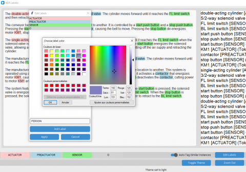
To address these issues, we developed a dedicated labeling tool called AutoLabel-NER, designed specifically for manufacturing requirement specifications. The tool allows users to import raw text, define and customize tags, and annotate components efficiently. When an entity is labeled, the tool automatically highlights similar terms across the text, which accelerates the annotation process. It also provides progress tracking and supports multiple export formats. The interface of the tool is shown in Figure 6.
Figure 6. Interface of AutoLabel-NER
Once the labeling process was completed, the annotated dataset was used to train a model for component extraction. The goal was to enable the system to automatically identify entities such as actuators, pre-actuators, and sensors in new requirement specifications. For this task, we fine-tuned the BERT model [22], which has shown strong performance in sequence labeling tasks such as named entity recognition. BERT was chosen for its ability to capture contextual relationships in text using a deep bidirectional transformer architecture. As shown in Table 1, BERT-Base includes 12 layers, 768 hidden units, and 12 self-attention heads, with a total of 110 million parameters. These settings offer a balance between model capacity and computational efficiency. The model was fine-tuned using our labeled dataset with a token-level classification objective, allowing it to learn how technical terms map to their corresponding component categories across a range of writing styles.
Table 1. Characteristics of pre-trained BERT base and large
|
Feature |
Description |
|
Release Date |
October 11, 2018 |
|
Parameters |
Base: 110M Large: 340M |
|
Layers / Hidden Dimensions / Self-Attention Heads |
Base: 12 / 768 / 12 Large: 24 / 1024 / 16 |
|
Training Time |
Base: 8 × V100 × 12d Large: 280 × V100 × 1d |
|
Performance |
Outperforming SOTA in Oct 2018 |
|
Pre-Training Data |
BooksCorpus + English Wikipedia = 16 GB |
|
Method |
Bidirectional Transformer, MLM and NSP |
To make the fine-tuning of BERT effective and reliable, the main training settings, called hyperparameters, were carefully optimized for this task. These include the learning rate, batch size, and number of training epochs. We used a grid search, which systematically tests different combinations, to identify the settings that offered the best balance between accuracy, stability, and efficiency. The final values, summarized in Table 2, were determined based on ablation experiments performed on the AutoFactory dataset.
The learning rate was tested across several values, and 5×10⁻⁵ consistently delivered the most stable convergence and highest F1 scores during these experiments. Batch sizes of 16 and 32 were selected because they provided efficient use of memory while maintaining stable model updates, which is important given the variable sentence lengths in the dataset. Although five training epochs were initially tested, the ablation results showed that three were sufficient to reach peak performance while avoiding overfitting. These optimized settings allowed the fine-tuned models to adapt effectively to the AutoFactory dataset while maintaining strong performance on unseen specifications.
Table 2. Hyperparameters and their values used in fine-tuning
|
Hyperparameter |
Description |
Values |
|
Learning Rate |
The step size for model updates during training. It controls how much to change the model in response to the estimated error each time the model weights are updated. |
[1e-4, 1e-5, 5e-5] |
|
Train Batch Size |
The number of samples processed before the model is updated. A larger batch size means more memory is required but can lead to more stable updates. |
[16, 32] |
|
Eval Batch Size |
The number of samples processed during evaluation. Similar to the train batch size, but used during the validation phase. |
[16, 32] |
|
Number of Training Epochs |
The number of complete passes through the entire training dataset. More epochs can lead to better learning but also risk overfitting. |
3 |
|
Tensorboard Logging Directory |
The directory for storing TensorBoard logs, which are used for visualizing the training process. |
"runs" |
|
Evaluate During Training |
A setting to enable evaluation of the model during the training process to monitor its performance. |
TRUE |
|
Early Stopping |
A technique to stop training when the model’s performance stops improving, to prevent overfitting. |
TRUE |
After training, the models were evaluated on a separate portion of the labeled dataset. Four metrics were used to assess performance: evaluation loss, precision, recall, and F1 score. Evaluation loss indicates how well the model fits the validation data. Precision is defined as the proportion of correctly predicted labels among all predicted labels:
Precision $=\frac{T P}{T P+F P}$ (1)
Recall measures the proportion of correctly predicted labels among all actual labels:
Recall $=\frac{T P}{T P+F N}$ (2)
The F1 score combines precision and recall into a single measure:
F1 Score $=\frac{2 \times \text { Precision } \times \text { Recall }}{\text { Precision }+ \text { Recall }}$ (3)
These metrics were computed at regular intervals during training and used to identify the best-performing model. Both BERT-Base and BERT-Large were fine-tuned using a fixed learning rate of 5 × 10⁻⁵ and a batch size of 16. These values were selected to ensure stable learning and efficient convergence. The evaluation results were stored in summary tables, and training curves were generated to visualize how performance metrics evolved across training steps.
After the components were detected in the requirement specification, the system assigned a function to each one. These functions were selected from a predefined library. Each entry in the library describes how a specific component behaves in an industrial system. For example, a cylinder may be linked to a function that defines how it extends and retracts, while a sensor may be linked to a function that checks its state. By assigning the correct function to each detected component, the system was able to recreate the behavior described in the original text.
Once all functions were assigned, the system combined them in the correct order to build the control logic. The final logic was then converted into Structured Text, following the IEC 61131-3 standard used in programmable logic controllers. This approach was designed to be modular. Each function can be reused, and new ones can be added without changing the rest of the system. This makes the method flexible and scalable. Control designers can describe different systems in natural language, and the same pipeline can generate structured and consistent code for each one.
This completes the core of the proposed pipeline. The component detection stage has been fully implemented and evaluated, and the results confirm that the system can reliably identify the key elements in natural language specifications. The final stage, which involves assembling complete logic structures and generating executable code for different types of industrial tasks, is still in development. We are currently building a diverse set of reusable control functions to cover a wide range of manufacturing scenarios.
The results presented in this section highlight the effectiveness of the proposed approach for extracting key components from natural language specifications in manufacturing systems. Using a dataset of over 2000 annotated descriptions written by control designers, we evaluate the ability of pretrained language models to identify entities such as actuators, pre-actuators, and sensors with high precision. Our analysis focuses on the structure of the dataset, the distribution of entity classes, the setup of the training process, and the comparative performance of BERT-Base and BERT-Large models. Through a series of figures and tables, we discuss the progression of training, the quality of predictions, and the trade-offs observed between model complexity and performance.
The dataset used in this study comprises 2135 natural language specifications written in English, each describing the intended behavior of components in automated manufacturing systems. To enable machine learning models to process this information, each specification was manually annotated using the BIO (Begin, Inside, Outside) tagging scheme. This format, consistent with the CoNLL-2003 standard [23], allows each token in the text to be tagged as either part of an entity (such as an actuator or sensor) or as general descriptive content. Three functional entity types were considered: actuators, pre-actuators, and sensors. All other tokens were labeled as "O", indicating that they do not represent a technical component. The final dataset contains over 76000 tokens distributed across training, validation, and test sets. The detailed breakdown is provided in Table 3.
Table 3. Annotated data distribution across training, validation, and test sets
|
Category |
Train |
Validation |
Test |
Total |
|
Specifications |
1708 |
213 |
214 |
2135 |
|
Sentences |
3416 |
426 |
428 |
4270 |
|
Tokens |
61065 |
7686 |
7669 |
76420 |
|
Actuators |
1708 |
213 |
214 |
2135 |
|
Pre-Actuators |
1708 |
213 |
214 |
2135 |
|
Sensors |
3416 |
426 |
428 |
4270 |
|
Others |
40385 |
5101 |
5073 |
50559 |
This distribution reveals that sensors are the most frequently occurring labeled entities, while actuators and pre-actuators appear in equal numbers. However, more than two-thirds of the tokens are labeled as "others", reflecting the descriptive nature of industrial specifications where control logic is embedded within broader contextual instructions.
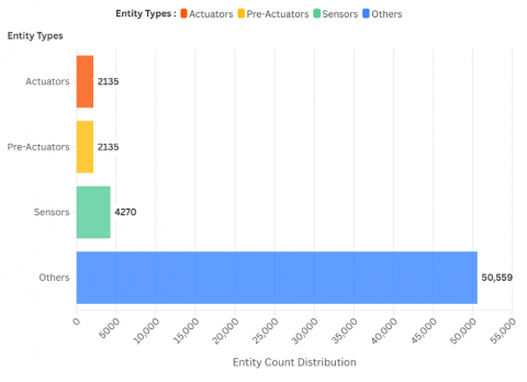
To further illustrate the entity composition of the dataset, Figure 7 presents the distribution of labeled tokens across the four categories: actuators, pre-actuators, sensors, and others. As the figure shows, the "others" category dominates the dataset, accounting for over 66% of all tokens. This is expected, as requirement specifications in manufacturing often contain auxiliary information such as conditions, timings, and structural details that are not tied to specific components. Among the functional entities, sensors appear most frequently, followed by balanced counts of actuators and pre-actuators. This distribution poses a learning challenge, as models must accurately distinguish relatively sparse entities within a majority of general-purpose language.
Figure 7. Distribution of labeled tokens by entity class
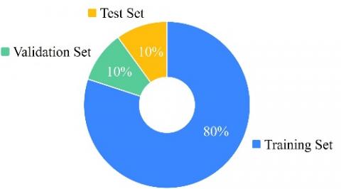
To ensure consistent evaluation and reliable generalization, the dataset was randomly divided into three subsets: 80% for training, 10% for validation, and 10% for testing. This split preserves the distribution of entity types across all partitions, which is essential to avoid bias during model assessment. The training set exposes the model to a diverse set of examples, while the validation and test sets allow for monitoring generalization and evaluating performance on unseen data. The proportions allocated to each subset are shown in Figure 8.
Figure 8. Proportions of training, validation, and test sets in the dataset
Table 4. Token-level annotations with part-of-speech and named entity labels [19]
|
Token |
POS |
POS ID |
NER Label |
NER ID |
|
This |
DT |
4 |
O |
0 |
|
setup |
NN |
8 |
O |
0 |
|
involves |
VBZ |
19 |
O |
0 |
|
a |
DT |
4 |
O |
0 |
|
double-acting |
JJ |
7 |
B-ACTUATOR |
1 |
|
cylinder |
NN |
8 |
I-ACTUATOR |
2 |
|
controlled |
VBZ |
18 |
O |
0 |
|
by |
IN |
6 |
O |
0 |
|
a |
DT |
4 |
O |
0 |
|
5/2-way |
JJ |
7 |
B-PREACTUATOR |
3 |
|
solenoid |
NN |
8 |
I-PREACTUATOR |
4 |
|
valve |
NN |
8 |
I-PREACTUATOR |
4 |
|
. |
. |
1 |
O |
0 |
|
|
|
|
|
|
|
The |
DT |
4 |
O |
0 |
|
cylinder |
NN |
8 |
O |
0 |
|
moves |
VBZ |
19 |
O |
0 |
|
forward |
RB |
13 |
O |
0 |
|
to |
TO |
14 |
O |
0 |
|
the |
DT |
4 |
O |
0 |
|
FL |
NNP |
9 |
B-SENSOR |
5 |
|
limit |
NN |
8 |
I-SENSOR |
6 |
|
switch |
NN |
8 |
I-SENSOR |
6 |
|
and |
CC |
2 |
O |
0 |
|
then |
RB |
13 |
O |
0 |
|
retracts |
VBZ |
19 |
O |
0 |
|
to |
TO |
14 |
O |
0 |
|
the |
DT |
4 |
O |
0 |
|
BL |
NNP |
9 |
B-SENSOR |
5 |
|
limit |
NN |
8 |
I-SENSOR |
6 |
|
switch |
NN |
8 |
I-SENSOR |
6 |
|
. |
. |
1 |
O |
0 |
To illustrate how specifications were annotated, Table 4 presents a labeled example taken directly from the dataset [19]. Each token is associated with its corresponding part-of-speech (POS) tag and named entity label using the BIO scheme. This format enables the model to identify not only the type of component (e.g., actuator or sensor) but also its span within the sentence. While the structure is compatible with CoNLL-2003 conventions, the vocabulary and domain-specific terms reflect the language commonly used by control designers. This approach allows the model to learn technical patterns in realistic industrial contexts.
After building and annotating the dataset, the next step was to set up the training and evaluation process. This part of the study aimed to test whether the models could correctly identify the main components mentioned in the specifications. These components include actuators, pre-actuators, and sensors. To perform this task, two models were used: BERT-Base and BERT-Large. BERT was chosen because it is designed to understand the meaning of words in context, which is important when identifying technical terms in full sentences. It has also shown strong performance in tasks where each word in a sentence must be labeled, such as named entity recognition. Both versions of BERT were fine-tuned on the annotated dataset. Fine-tuning means taking a model that has already learned from general English texts and continuing its training on a specific dataset, so it can adapt to the language and structure of the domain.
To fine-tune the models on the annotated dataset, a systematic grid search was conducted to identify the optimal training configuration. We explored different combinations of learning rates and batch sizes for both BERT-Base and BERT-Large while keeping the number of training epochs fixed at three. This setup ensured a fair comparison of model capacity under consistent training conditions. The learning rates tested were 1e-5, 3e-5, and 5e-5, and batch sizes of 16 and 32 were evaluated. Each model was trained to minimize evaluation loss and maximize precision, recall, and F1 score.
Table 5 presents the full results of the grid search. BERT-Base achieved its best performance with a learning rate of 5e-5 and batch size of 16, reaching an F1 score of 0.9711, precision of 0.9778, and recall of 0.9688. BERT-Large also performed well, with its highest F1 score of 0.9667 under the same learning rate and batch size. These results confirm that both models can accurately detect components in manufacturing specifications, with BERT-Base showing slightly more stable performance across configurations.
Table 5. Grid search results for BERT-Base and BERT-Large fine-tuned on the AutoFactory dataset
|
Model |
Epochs |
Learning Rate |
Batch Size |
Evaluation Loss |
F1 Score |
Precision |
Recall |
|
BERT Base |
3 |
0.00001 |
16 |
0.0931 |
0.9494 |
0.9421 |
0.9569 |
|
0.00003 |
16 |
0.0651 |
0.9642 |
0.9594 |
0.9670 |
||
|
0.00005 |
16 |
0.0446 |
0.9711 |
0.9778 |
0.9688 |
||
|
0.00001 |
32 |
0.0998 |
0.9453 |
0.9371 |
0.9536 |
||
|
0.00003 |
32 |
0.0566 |
0.9663 |
0.9634 |
0.9672 |
||
|
0.00005 |
32 |
0.0634 |
0.9659 |
0.9631 |
0.9678 |
||
|
BERT Large |
3 |
0.00001 |
16 |
0.0973 |
0.9528 |
0.9463 |
0.9595 |
|
0.00003 |
16 |
0.0582 |
0.9637 |
0.9679 |
0.9597 |
||
|
0.00005 |
16 |
0.0746 |
0.9667 |
0.9628 |
0.9707 |
||
|
0.00001 |
32 |
0.0931 |
0.9498 |
0.9464 |
0.9532 |
||
|
0.00003 |
32 |
0.0684 |
0.9613 |
0.9618 |
0.9608 |
||
|
0.00005 |
32 |
0.0810 |
0.9582 |
0.9594 |
0.9571 |
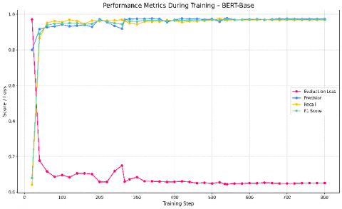
During training, we monitored key performance metrics to evaluate how well the model was learning over time. These metrics included evaluation loss, precision, recall, and F1 score. Figure 9 shows how BERT-Base progressed across these indicators throughout 801 training steps. In the early stages, the model exhibited rapid improvements in both recall and precision, reflecting its ability to capture component patterns from the training data. Around step 200, performance stabilized, and the F1 score consistently remained above 0.96 in the later stages of training. The evaluation loss decreased steadily, indicating improved generalization. These results suggest that BERT-Base effectively adapted to the domain and was able to extract relevant entities from technical language with high accuracy.
Figure 9. Performance metrics during training – BERT-base
To assess the influence of model capacity, we also tracked the performance of BERT-Large using the same training configuration. As shown in Figure 10, BERT-Large reached high scores early in training and exhibited stable improvements over time. While its F1 score surpassed 0.96 after approximately 200 steps, the overall curve showed more fluctuation compared to BERT-Base, particularly in the earlier and middle phases of training. Despite these variations, the model achieved competitive results, with its final F1 score nearing that of BERT-Base. The evaluation loss also followed a downward trend, confirming the model’s ability to generalize well. These results indicate that BERT-Large benefits from its greater capacity to model complex patterns, but this also comes with a slightly less stable training curve.
Figure 10. Performance metrics during training – BERT-large
To provide a clear summary of performance, we compared the best evaluation metrics achieved by each model using a grouped bar chart. As shown in Figure 11, BERT-Base slightly outperformed BERT-Large across most metrics. It reached the highest F1 score of 0.9711, along with strong precision, recall, and a lower evaluation loss. While BERT-Large also delivered competitive results, its peak scores remained slightly lower under the same training conditions. This outcome suggests that BERT-Base offers a strong balance between performance and stability for the task. However, it is worth noting that BERT-Large has greater capacity and may yield better results if trained with a different learning rate, batch size, or number of epochs. Further hyperparameter tuning and model-specific adjustments could improve its performance in future work.
Figure 11. Best evaluation metrics: BERT-base vs BERT-large
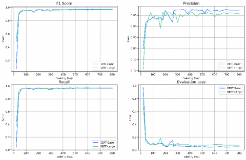
Figure 12. Overlay comparison of BERT-base and BERT-large across four metrics
To better understand how the two models evolve over time, we plotted their training curves together for all key metrics: F1 score, precision, recall, and evaluation loss. Figure 12 provides this side-by-side visualization. The results show that both models followed similar learning patterns, with BERT-Base displaying slightly more stable trajectories across most metrics. BERT-Large showed stronger performance in some early stages but exhibited greater variability, especially in precision and recall. Despite these fluctuations, its scores converged closely with those of BERT-Base by the final training steps. This overlay comparison confirms that both models are capable of capturing the structure of technical language in manufacturing specifications, but BERT-Base maintained a more consistent learning behavior throughout the training process.
The results obtained from the component extraction step demonstrate that the BERT models are capable of accurately identifying actuators, pre-actuators, and sensors from structured technical descriptions. This confirms that the system can process manufacturing requirements written in natural language and extract the functional elements necessary for automation. The extraction process is now stable and precise, providing a reliable foundation for the next phase of our work.
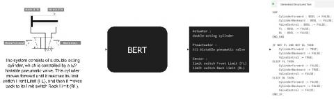
Figure 13. Pipeline showing component extraction and code generation from natural language specification
As shown in Figure 13, once the key components are identified by the model, the system can proceed to structure them into meaningful control logic. We are currently developing the module responsible for generating function definitions and control routines based on these extracted elements. This step aims to automatically produce Structured Text code that conforms to industrial standards. By extending the system in this direction, we move closer to fully automating the translation of requirement specifications into executable PLC programs scenarios.
Writing control programs for manufacturing systems requires time, precision, and expert knowledge. This process often begins with a requirement specification written in natural language and ends with manually developed code for programmable logic controllers. As systems become more complex, this manual approach becomes difficult to scale and maintain. The work presented in this study addresses this challenge by exploring how artificial intelligence can support control designers by interpreting natural language specifications and automating part of the code generation process.
In this study, we introduced a step-by-step approach that allows computers to understand and process natural language specifications in manufacturing. The system starts by identifying important components such as actuators, pre-actuators, and sensors. To do this, we trained two BERT models on a dataset created specifically for this task. Once the components are detected, each one is linked to a function that describes how it should behave. These functions are then combined to form a complete control program. The final code is written in Structured Text, a language used in industrial automation. This method reduces manual effort, improves consistency, and prepares the way for future automation of control program development.
The results showed that both BERT-Base and BERT-Large were able to detect components from specifications with high accuracy. BERT-Base achieved the highest F1 score of 0.9711, while BERT-Large reached 0.9667 under the same training settings. Both models performed well in terms of precision and recall, confirming their ability to generalize across different writing styles. BERT-Base demonstrated a more stable learning curve, while BERT-Large showed greater capacity but with some variation during training. These results confirm that pretrained language models can understand technical language and extract useful information from it with very good performance.
While the system successfully detects key components such as actuators, pre-actuators, and sensors from natural language specifications, the full pipeline is not yet complete. At this stage, the system stops after identifying components and assigning corresponding functions. It does not yet build the complete control logic or generate fully structured and validated control code. Another limitation is that the dataset, although built from realistic examples, may not cover all ways control designers write specifications in different industrial settings. These limitations define the current boundary of the work and highlight areas for future improvement.
The next stage of this work will complete the development of the pipeline so that it can produce fully validated control programs ready for industrial use. The pipeline will take a natural language requirement specification as input and automatically generate Structured Text code as output. It will include logic assembly, simulation, and formal verification to ensure the generated programs are correct and reliable. The Structured Text will comply with the IEC 61131-3 standard and will be exported as project files compatible with Siemens TIA Portal and Schneider EcoStruxure. This will allow engineers to test, simulate, and deploy the generated programs directly in their existing industrial workflows, making the system easy to adopt.
Following these improvements, the dataset will be expanded to cover all manufacturing scenes available in Factory I/O, a 3D simulation platform for industrial automation. For each scene, multiple requirement specifications will be written by different designers. These will include augmented variations for linguistic diversity, detailed tag tables, screenshots from multiple angles, and the original 3D scene files. This expansion will allow the pipeline to be tested from end to end, starting with natural language input and ending with deployment-ready code that can be validated in simulation and industrial development environments.
In parallel, the AutoLabel-NER tool will be upgraded to include semi-automatic annotation. This feature will allow the tool to suggest labels based on model predictions, which human annotators can quickly confirm or correct. This upgrade will speed up dataset creation and improve labeling consistency, helping accelerate model training and evaluation.
In the longer term, we plan to develop a full prototype tool that integrates all stages of control program generation into a single system. This tool will combine component extraction, logic mapping, simulation, and formal verification in one unified interface. These developments will lead to a robust toolchain that converts natural language specifications into tested, ready-to-use control code for both virtual and real manufacturing systems.
The models were fine-tuned on a local machine equipped with an NVIDIA GeForce RTX 5080 GPU, an Intel Core i9 14th-generation processor, 64 GB of DDR5 RAM, and a 1 TB SSD. The experiments were conducted on Windows 11 using Python 3.12.7. Training was performed using the Simple Transformers library built on top of Hugging Face Transformers.
[1] Boppana, V.R. (2024). Industry 4.0: Revolutionizing the future of manufacturing and automation. Available at SSRN 5135027. https://doi.org/10.2139/ssrn.5135027
[2] Winch, G.M. (2022). Projecting for sustainability transitions: Advancing the contribution of Peter Morris. Engineering Project Organization Journal, 11(2): 16. https://doi.org/10.25219/epoj.2022.00101
[3] Groumpos, P.P. (2021). A critical historical and scientific overview of all industrial revolutions. IFAC-PapersOnLine, 54(13): 464-471. https://doi.org/10.1016/j.ifacol.2021.10.492
[4] Aoun, A., Ilinca, A., Ghandour, M., Ibrahim, H. (2021). A review of Industry 4.0 characteristics and challenges, with potential improvements using blockchain technology. Computers & Industrial Engineering, 162: 107746. https://doi.org/10.1016/j.cie.2021.107746
[5] Ryalat, M., ElMoaqet, H., AlFaouri, M. (2023). Design of a smart factory based on cyber-physical systems and Internet of Things towards Industry 4.0. Applied Sciences, 13(4): 2156. https://doi.org/10.3390/app13042156
[6] Javaid, M., Haleem, A., Singh, R.P., Suman, R. (2022). Enabling flexible manufacturing system (FMS) through the applications of Industry 4.0 technologies. Internet of Things and Cyber-Physical Systems, 2: 49-62. https://doi.org/10.1016/j.iotcps.2022.05.005
[7] Xia, C., Liu, Y., Xia, T., Jin, X., Xu, C., Zeng, P. (2022). Control-communication-computing co-design in cyber-physical production system. IEEE Internet of Things Journal, 10(6): 5194-5204. https://doi.org/10.1109/JIOT.2022.3221932
[8] Napoleone, A., Negri, E., Macchi, M., Pozzetti, A. (2023). How the technologies underlying cyber-physical systems support the reconfigurability capability in manufacturing: A literature review. International Journal of Production Research, 61(9): 3122-3144. https://doi.org/10.1080/00207543.2022.2074323
[9] Oluyisola, O.E., Bhalla, S., Sgarbossa, F., Strandhagen, J.O. (2022). Designing and developing smart production planning and control systems in the Industry 4.0 era: A methodology and case study. Journal of Intelligent Manufacturing, 33(1): 311-332. https://doi.org/10.1007/s10845-021-01808-w
[10] Sahoo, S., Lo, C.Y. (2022). Smart manufacturing powered by recent technological advancements: A review. Journal of Manufacturing Systems, 64: 236-250. https://doi.org/10.1016/j.jmsy.2022.06.008
[11] Boudribila, A., Tajer, A., Boulghasoul, Z. (2024). From natural language to code: AI automation in cyber-physical manufacturing systems. In 2024 World Conference on Complex Systems (WCCS), Mohammedia, Morocco, pp. 1-6. https://doi.org/10.1109/WCCS62745.2024.10765530
[12] Boudribila, A., Chadi, M.-A., Tajer, A., Boulghasoul, Z. (2023). Large language models and adversarial reinforcement learning to automate PLCs programming: A preliminary investigation. In 2023 9th International Conference on Control, Decision and Information Technologies (CoDIT), Rome, Italy, pp. 650-655. https://doi.org/10.1109/CoDIT58514.2023.10284185
[13] Deshmukh, J.V., Sankaranarayanan, S. (2019). Formal techniques for verification and testing of cyber-physical systems. In Design Automation of Cyber-Physical Systems, pp. 69-105. https://doi.org/10.1007/978-3-030-13050-3_4
[14] Lecomte, T., Déharbe, D., Prun, É., Mottin, E. (2017). Applying a formal method in industry: A 25-year trajectory. In Formal Methods: Foundations and Applications Methods. Springer, Cham, pp. 70-87. https://doi.org/10.1007/978-3-319-70848-5_6
[15] Garavel, H., Ter Beek, M.H., Van De Pol, J. (2020). The 2020 expert survey on formal methods. In International Conference on Formal Methods for Industrial Critical Systems, pp. 3-69. https://doi.org/10.1007/978-3-030-58298-2_1
[16] Fischer, J., Vogel-Heuser, B., Huber, C., Felger, M., Bengel, M. (2021). Reuse assessment of IEC 61131-3 control software modules using metrics - An industrial case study. In 2021 IEEE 19th International Conference on Industrial Informatics (INDIN), Palma de Mallorca, Spain, pp. 1-8. https://doi.org/10.1109/INDIN45523.2021.9557357
[17] Qamsane, Y., Tajer, A., Philippot, A. (2017). Towards an approach of synthesis, validation and implementation of distributed control for AMS by using events ordering relations. International Journal of Production Research, 55(21): 6235-6253. https://doi.org/10.1080/00207543.2017.1333648
[18] Qamsane, Y., Tajer, A., Philippot, A. (2017). A synthesis approach to distributed supervisory control design for manufacturing systems with Grafcet implementation. International Journal of Production Research, 55(15): 4283-4303. https://doi.org/10.1080/00207543.2016.1235804
[19] Boudribila, A. (2025). AutoFactory. Hugging Face. https://doi.org/10.57967/hf/5011
[20] Leng, J., Wang, D., Shen, W., Li, X., Liu, Q., Chen, X. (2021). Digital twins-based smart manufacturing system design in Industry 4.0: A review. Journal of Manufacturing Systems, 60: 119-137. https://doi.org/10.1016/j.jmsy.2021.05.011
[21] Brown, T., Mann, B., Ryder, N., Subbiah, M., et al. (2020). Language models are few-shot learners. Part of Advances in Neural Information Processing Systems 33 (NeurIPS 2020).
[22] Devlin, J., Chang, M.W., Lee, K., Toutanova, K. (2019). BERT: Pre-training of deep bidirectional transformers for language understanding. In Proceedings of the 2019 Conference of the North American Chapter of the Association for Computational Linguistics: Human Language Technologies, Minneapolis, Minnesota, pp. 4171-4186. https://doi.org/10.18653/v1/N19-1423
[23] Sang, E.F.T.K., De Meulder, F. (2003). Introduction to the CoNLL-2003 shared task: Language-independent named entity recognition. arXiv preprint cs/0306050. https://doi.org/10.48550/arXiv.cs/0306050