Ayushi Jain![]() | Durgesh Nandan*
| Durgesh Nandan*![]() | Pramoda Meduri
| Pramoda Meduri![]()
(This article is part of the Special lssue Technology Innovations and AI Technology in Healthcare)
© 2023 IIETA. This article is published by IIETA and is licensed under the CC BY 4.0 license (http://creativecommons.org/licenses/by/4.0/).
OPEN ACCESS
As know, the autonomy level grows up, and the number of data exchanged between cars will be more. Several electronic parts have recently been added to automobiles, increasing the data and storage of cars. An internal network that communicates pertinent information status about the vehicle and is aware of a specific signal is built by the electronic components. The automobile has taken action to address this data and storage issue by making the CAN database (also known as a DBC format file), which contains the signal information assigned in the CAN data payload, secure. This paper demonstrates a method for gathering data from ECU, making it understandable to humans, and sending data or a wireless internet communication using an IOT platform. As a result, we suggest a solution: data must be compressed for quicker and more secure transmission. Data compression is performed before data transmission, it is used for reducing the number of bits used for each piece of data. Moreover, source encoding is necessary to restrict the size of data storage files. The three stages of this research are “CAN-bus data gathering, CAN data compression, and data transmission to cloud storage.” By research, three objectives to identify the compression ratio, Graphical User Interface (GUI), and integration will be achieved. Unlike an existing method that is designed based on messages and signals with the Bit start, Bitlength, and CAN data payload in this study, we demonstrate that our method outperforms the current way of using a publicly accessible DBC format file named Open DBC as a reference.
connected car, data compression, MQTT cloud, CAN DBC format file, Graphical User Interface (GUI)
Introducing the “connected vehicle (CV) guidance system”, a brand-new category of guiding system. This system makes use of connected car [1] technology to achieve dynamic vehicle guidance. The “CV guidance system” enables dynamic guiding for “ECU network flow” through “’real-time Signal information” and is based on “vehicle-to-vehicle [2] (V2V), vehicle-to-infrastructure (V2I), and vehicle-to-smart terminal (V2T) technologies”. The connections in modern cars can be internal (like the bus systems that link the sensors and processors inside, for example) or external (like the protocols that allow connectivity between passing vehicles). The connected car [3], which is a vehicle with Internet connectivity, communication capabilities with other vehicles and road infrastructure, and the ability to gather real-time data from multiple sources, is predicted to be a key player in the future Internet of Things [4]. With the support of hardware and software that facilitate widespread knowledge transfer rapidly via the internet, around the world, technology is developing [5] quickly. Information technology professionals can effortlessly by sending information over the internet. Not all data can be sent easily, though. A method of transforming data from one representation to another compressed (in bits) representation that retains the same information but is as small as possible is known as data compression. By deleting unwanted or duplicated information, the size of the data is decreased. Reduced storage and/or communication costs allow for the storage [6] or transmission of the data. By compressing a file to half its original size, the storage medium's capacity is increased. When this occurs, it might be possible to store the data higher up in the storage hierarchy, which would ease the load on the system's input/output channels. Lossless and Lossy compression are two different compression methods. The input image and the reconstructed image are identical in a lossless compression [7] strategy. Techniques for lossless picture compression first divide the images into their component pixels. Comparing lossy and lossless compression, lossy compression offers a higher compression ratio. With this process, there is some information loss in the compressed image, which makes it different from the original image. The entire transmission of information at a specific time is the basic objective of digital communications. If the data being transferred is huge, it will be challenging to accomplish this goal because larger data take longer to transmit fully. The “Huffman Algorithm, Lempel-Ziv Algorithm, Shannon-Fano Elias Encoding, Arithmetic Coding [8], and Adaptive Coding” are only a few of the source coding methods that are accessible. The bulk of ECUs shares important status information about the vehicle using the “controller area network (CAN) protocol”, which is the de facto standard for in-car network connectivity. To prevent hackers from learning about CAN [9] messages that control crucial commands, automakers have made the data in the “CAN database confidential (i.e., DBC format file)”. Some studies have tried to recreate a DBC format file to lessen this. Invasive and non-invasive strategies can be used to classify these attempts. The intrusive technique involves disassembling cars to directly examine an ECU and check its programming. The non-invasive method may be preferable for reconstruction because the intrusive procedure can easily be stopped by any preventative measure, like turning off a debugging port. This paper's major objective is to create an embedded system that can connect to an M2M broker, connect with other integrated devices using a cloud server, and be changeable using a cloud-based web service. The MQTT protocol was selected for this study's aims because it seemed to best fit the requirements presented. Using a publish-subscription architecture, MQTT [10] is an open-source TCP protocol. Clients "subscribe" to desired subjects in publish-subscribe ("pub-sub") by connecting to a central broker. Any client nodes that have subscribed to that topic will get any messages that a client "publishes" to. Since it is a TCP-based protocol, MQTT has a comparatively high overhead but also offers a high level of guaranteed [11] Quality of Service (QoS) and allows both one-to-one and one-to-many messages. MQTT is reasonably simple to utilize for apps thanks to its many open-source libraries and active support community.
For effective graphic user interface design and development, intelligent software and tools are needed. These tools are utilized when creating designs, beautifying the GUI [12], and acquiring necessary data. Utilizing these technologies has advantages such as a streamlined design tool that enables you to ship better designs more quickly. better typography, redlines, colors, measurement, and other tools. This survey offers a thorough examination of the instruments. Different frameworks and tools, including Figma, Whimsical, and Open Dataset, are examined based on their features and intended uses. We developed the Connected-Car Prototyping [13] Framework and repeatable program templates to enable the prototype of informatics services. The platform and templates speed up the time to market and make it easier to produce prototypes. They are constructed using cloud concepts to reduce the initial setup costs for prototypes and boost scalability. It is now simple to provide connected services that are online applications for desktops thanks to a range of tools and back-end technologies. For numerous Web platforms and programming languages, these frameworks and platforms provide software development kits. They frequently offer services like data storage, data compression, and enhancement of application development. Time-to-market and flexibility become essential when future client demand is unknown. We created the Connected-Car Prototyping [14] Platform to overcome these issues and make telematics and cloud service development simpler. It offers a back end for programs communicating with an automobile's ECU.
In this paper [15], For most of the text files, the combination of the RLE and LZW compressors will result in somewhat better compression than either RLE or LZW alone. Since both the RLE and the LZW algorithms take benefit of common redundancy in text-based files (i.e., repetitiveness or multiple examples of phrases), combining this is beneficial. An aspect of the two algorithms into one algorithm can lead to better results than the individual performance, but in the end, they find that individual performance gives more compression ratio.
In this paper [16], their text data was limited, so they evaluated only three lossless data compression algorithms. In the future, they plan to test lossless and lossy compression algorithms on audio, video, and image data. LZW performs better than the other two algorithms when it comes to de-compressed file size, but when it comes to compression, they discovered that LZW takes a lot longer to compress a file than the other two methods. IoT application principles are discussed in this study. In terms of “power, security, QoS, communication, and durability”, we also put more of emphasis on benchmarking and contrasting [17] “HTTP, MQTT, DDS, XMPP, AMQP, and CoAP”. Some ap-plications are introduced using the benefits and drawbacks of each protocol in connection to other user rules to simplify this comparison. Comparatively speaking, MQTT is a very efficient protocol [18].
In this paper [19], the Author used ESP8266 for their high-end application i.e., a smart irrigation system using the Internet of things; to operate the system wirelessly using an application called Blynk.
According to them [20], the “MCP2515 TJA1050 CAN-bus converter” board is the optimum method for gathering data from ECUs due to data clocking for each frame of data packets. Data from the ECU is sent to the cloud utilizing the REST architectural approach and an ESP8266 Wi-Fi module. By using software that can create algorithms and transfer data using the HTTP request Protocol.
In this paper [21], they presented GUI Fetch, a code-search method that makes use of the rising number of open-source applications available in public repositories to give users access to code that may be utilized as a starting point for the apps they want to create. In addition to supporting early prototyping and giving developers a place to start when creating GUI-based apps, GUI may also assist designers in determining whether or not there are already apps that are similar to the one they want to create. They put GUI Fetch into practice for Android apps and tested it out empirically.
To help you understand our process more clearly, we've included some background information in this section.
3.1 In-vehicle network
Many car features are electronically regulated for the comfort and safety of the driver. A modern automobile has several ECUs fitted to run the digital features. The status of a vehicle is periodically measured by ECUs, and some operations are controlled based on these observations. The ECU either starts the engine on its own or sends instructions to another ECU to start the engine based on the measurement. Vehicles can function more safely and effectively thanks to this automated control system, and more are being created all the time. Modern luxury cars frequently have a number of ECUs fitted. A group of ECUs creates an internal network within the vehicle where they can communicate. The internal network can be further subdivided into sub-networks based on comparable functions. An ECU communication protocol, such as LIN, CAN, or Flex Ray, is re-quired for in-vehicle networks. The CAN protocol, which offers a limited transmission delay between ECUs, is the most popular of them.
3.2 CAN protocol
The two distinct frame formats that are provided in the CAN standard are the “standard frame format and the extended frame format (only described in CAN 2.0 B) [22]”. In contrast to the regular frame format, which only supports an “11-bit identifier, the extended frame format supports a 29-bit identification that is made up of the 11-bit identity plus an 18-bit extended identifier”. Most ECUs in a car is smaller than 2 power 11 and communicate with one another using the common frame format. “Data, remote, error, and overload frames” are the four main frame types used by ECUs to exchange data inside an “in-vehicle CAN network”. Data frame messages are the most typical CAN communications that ECUs send. A CAN data frame includes fields including an “identifier (ID), data length code (DLC), data, and cyclic redundancy check (CRC)”, as seen in Tables 1 and 2. The three stages involved in the process are as follows:
Table 1. Standard CAN frame format
|
SOF |
11 Bit Identifier |
RTR |
IDE |
R0 |
DLC |
|
DATA up to 8 Bit |
CRC |
ACK |
EOF |
IFC |
|
Table 2. Extended CAN frame format
|
SOF |
11 Bit Identifier |
S RR |
IDE |
18 Bit Identifier |
RTR |
R1 |
|
R0 |
DLC |
DATA UPTO 8 Bit |
CRC |
ACK |
EOF |
IFS |
Instead of the receiver's identifier, the identifier field relates to the transmitters. In general, it is expected that ECUs do not share the same identifier and that a single ECU has several identifiers. Typically, manufacturers go to tremendous lengths to maintain the secrecy of which identifiers correspond to which functions.
3.3 Structure of data payload field
There must be at least one signal in a CAN data payload [23]. A signal is a bit of information that an ECU sends, like a car speed or the rotational speed of its wheels. The DBC format file for the appropriate vehicle specifies the length and quantity of the signals, which change depending on the CAN ID. Our method is intended to count the list of signals and their length in CAN data without the use of a DBC format file by analyzing CAN traffic. Additionally, signals include a variety of information types, including the following.
The values of a physical value signal, such as the speed of the wheels or the angle of the steering wheel, correspond to a physical state of a vehicle. As a result, various signals are transmitted over a CAN network inside the car. A signal called a counter always has a value that is one higher than the previous message. For a certain CAN ID, the counter allows “verification of the ECU transmitting messages”. Additionally, a receiving ECU can identify a retransmission of a previously received CAN message. A signal called a checksum contains the results of a checksum on a payload of data. Checksums frequently find transmission mistakes. Although the CRC field in the CAN data is specified, some manufacturers provide a second checksum field in the CAN data to enable a more robust, dependable CAN connection in their vehicles. An unchanging signal is one that is unused or constant. The DBC format file standard states that a signal's maximum and minimum values may be the same. It suggests a constant. Additionally, unused fields can be given to some bits in a data payload.
3.4 Data compression
Digital data transmission and reception are the focus of digital communications. These kinds of data can hold the data that must be conveyed. It can be in text, image, video, document, among other formats. Prior to transmission, the data must be transformed into digital format, which produces a stream of bits with a logic value of either 1 or 0. These details must always be transmitted in full at a specific time. Source encoding is employed in this situation to make up for it. Source encoding is a method for lowering the typical number of bits utilized for a particular file. To maximize data transfer, this is utilized to compress the data.
There are different kinds of source coding methods, including the “Shannon-Fano Algorithm, Lempel-Ziv Algorithm, and Huffman Algorithm”. “The Huffman and Lempel-Ziv algorithm” is the most often utilized of these since it produces code words with high compression ratios and a short average length. The entire transmission of information at a specific time is the basic objective of digital communications. If the data being transferred is huge, it will be challenging to accomplish this goal because larger data take longer to transmit fully.
The applications of the Huffman and Lempel-Ziv Algorithms, two source encoding methods, to many sorts of data formats, only text, are the main emphasis of this study. These algorithms were widely utilized because they produce code words with short average lengths and high compression ratios.
3.4.1 Huffman algorithm
The “Huffman code” is a variable-length, “prefix-free code” that can achieve the shortest codeword length for a given symbol that may be longer than its entropy. In this algorithm, the least frequent symbol is given the fewest bits, followed by the most frequent symbol given the most bits. ASCII character data compression is the focus of Huffman coding. Numerous types of data, including text, audio, video, and images, are compressed using it. This method is based on developing a complete binary tree for each symbol in the original file after figuring out the probability of each symbol and sorting the symbols by reducing probability. Lossless compression techniques are included in the Huffman compression algorithm [24]. A compression technique known as lossless compression does not alter the underlying data information to make it smaller.
Huffman's approach is that each ASCII character is typically represented by 8 bits. As an illustration, if a file has the character "UUVWX" in a row, it has 40 bits, 5 bytes, or 5 bits. We only require a file that is 10 bits in size (0010111110) if each character is assigned a code, such as U=0, V=10, W=111, or X=110. that specifies that codes must be identical, or that a code cannot be generated from some other code.
3.4.2 Run length encoding
RLE, also known as run-length encoding, is the most straightforward data compression approach. This algorithm distinguishes between runs and non-runs by identifying successive symbol sequences as runs. This algorithm handles a certain amount of redundancy. Based on their redundancies and their lengths, it evaluates whether there are any repetitive symbols. All other sequences are regarded as non-runs, while consecutive recurrent symbols are labelled as runs. For instance, if the file "AYAZZZZA" is chosen to optimize, the first three letters are regarded as a non-run with a length of 3, while the following four characters are regarded as a run with a length of 4 because the symbol Z is repeated. This algorithm's primary priority is to locate the runs in the source file and to mark each run's symbol and length [25]. While storing all the non-runs and not using any of those runs for the compression process, the RLE algorithm uses those runs to optimize the main research file.
The Run Length Encoding Algorithm and others are implemented and analyzed in a set of data files to calculate the performance of the lossless compression technique. The mentioned factors are evaluated to measure results.
3.4.3 Lempel Zev Welch algorithm
In general, the LZW method uses a dictionary and is a lossless compression algorithm. Dictionary-based techniques do this instead of having a statistical model as their core. A dictionary is a collection of all words that can be used in a language. Larger and more frequent dictionary words are represented by the entries' indexes, which are preserved in a table-like format. The most popular method is known as the LZW algorithm [26]. Instead of repeating string patterns, these index values are used during compression. Instead of using repetitive string patterns, these index values are used during compression. The dictionary is generated dynamically during the compression process; thus, it is not necessary to send it along with the encoded message for decompression. During decom-pression, the same dictionary is dynamically created.
3.4.4 Evaluate the performance of the different algorithms
Depending on the application, a compression algorithm's performance can be evaluated using a variety of factors. As a result, calculating effectiveness is challenging, and many measurements should be used to analyze the performance of those compression categories. The measurements used to evaluate how well lossless algorithms work are listed below.
Compression Ratio: It describes the proportion of the source file's size to the compressed file's size.
$C R=\frac{\text { Size after compression }}{\text { size before compression }}$
Saving percentage:
Saving %$=\frac{\text { size before compression }- \text { size after compression }}{\text { size before compression }}
$
Compression factor: It is the absolute opposite of compression ratio.
$C F=\frac{\text { Size before compression }}{\text { size after compression }}$
The relative compression ratios, compression factor, and saving percentage for each compression approach are shown in Table 3 and, as can be seen. Of all the data sets, the run length encoding has the most reasonable compression ratio. RLE is hardly ever used in lossless data compression today. The Huffman encoding approach, which focuses solely on minimizing input data redundancy, is the optimal alternative based on what is currently known about compression ratio. Although, Huffman encoding, which provides a moderate compression percentage and factor. The success of Lempel-Ziv-Welch encoding in obtaining higher compression ratios depends in large part on dictionary size.
Table 3. Shows the comparison between saving%, compression factor, and ratio
|
File size |
Run length encoding |
Huffman encoding |
LZW method |
|
|
4096 |
Compressed file |
1919 |
1650 |
1450 |
|
Compression ratio |
0.468 |
0.402 |
0.354 |
|
|
Compression Factor |
2.134 |
2.487 |
2.824 |
|
|
Saving Percentage |
53.14% |
59.71% |
64.59% |
|
|
16384 |
Compressed file |
7707 |
6707 |
5707 |
|
Compression ratio |
0.470 |
0.409 |
0.348 |
|
|
Compression Factor |
2.127 |
2.444 |
2.873 |
|
|
Saving Percentage |
52.96% |
59.06% |
65.16% |
|
|
1024 |
Compressed file |
500 |
450 |
314 |
|
Compression ratio |
0.488 |
0.439 |
0.306 |
|
|
Compression Factor |
2.049 |
2.277 |
3.267 |
|
|
Saving Percentage |
51.11% |
56.05% |
69.30% |
|
|
65536 |
Compressed file |
35530 |
29930 |
19646 |
|
Compression ratio |
0.542 |
0.456 |
0.299 |
|
|
Compression Factor |
1.847 |
2.192 |
3.344 |
|
|
Saving Percentage |
45.78% |
54.33% |
70.20% |
|
|
262144 |
Compressed file |
131144 |
92534 |
65300 |
|
Compression ratio |
0.500 |
0.352 |
0.249 |
|
|
Compression Factor |
2 |
2.840 |
4.016 |
|
|
Saving Percentage |
49.97% |
64.70% |
75.03% |
|
3.5 GUI design
As a starting point for designing our platform, we initially gathered high-level functional and non-functional requirements. A GUI's main objective is to free the user up to focus on the current task. The interface between a human and a computer must be flawless for this to happen. An effective GUI [27] design eliminates the barrier to user-computer communication and enables focus on the issue at hand. The market success of today's software applications relies on effective GUI design since a good GUI makes an application simple, useful, and efficient to execute. There are numerous ways to present information given a collection of data to display. The readability of the material is enhanced by proper grouping, which can also highlight connections between the information. Three selectable tabs have been used to organize the GUI information.
•Technical details and evaluation: The user must specify their name (for login credentials) and, if desired, the name of the testing organization. Other information about the car may be recorded, such its physical value, arbitration ID, hexadecimal value, vehicle identification (year of launched) etc. On the other hand, the vehicle model-dependent signal measurement parameters that are dynamically modifiable can be calibrated online.
•Real – Time data: Real-time data enables the user to view signal information immediately or as needed.
•Historical data record: Information from the database may be accessed and viewed, and it can also be compressed.
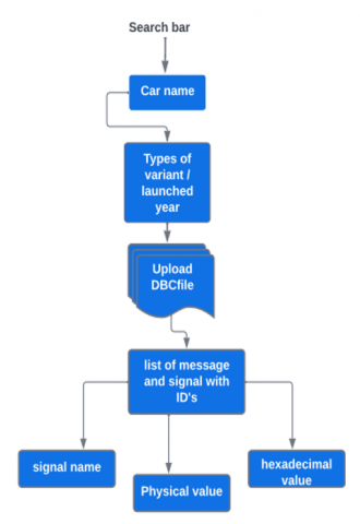
This Figure 1 shows the flowchart of GUI design, it describes how we design the GUI for our research so there are some steps:
• First, search for the Car name (for example i.e... Maruti) it will fetch the data from the database.
• After showing the data of the Car, it shows the data of the variant and launched a year of data.
• There is an option for uploading a DBC text file.
• After uploading the file, it will show the list of messages and signals with CAN ID.
• After getting lists, we can get Real-time data of all signals which we selected.
Figure 1. Flowchart of GUI web design
CAN DBC format file: DBC files are sometimes used to refer to database files for CAN.
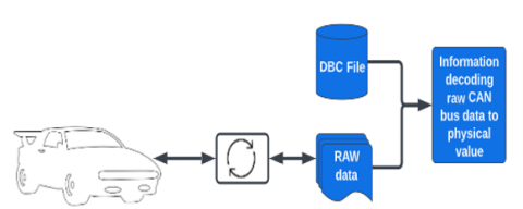
A straightforward text file called a DBC file offers instructions for turning raw CAN bus [28] data into numbers or into a human-readable format. The DBC file is offered since it is the most often used method of managing data identification and translation. In order to provide a mechanism to retain records in a CAN network, the DBC file [29] format was developed as shown in Figure 2.
Figure 2. CAN data using DBC file
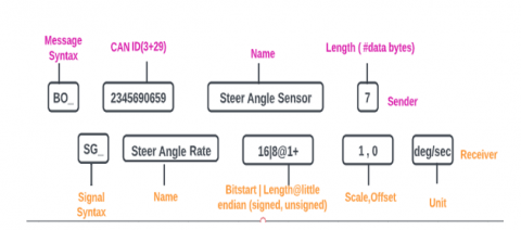
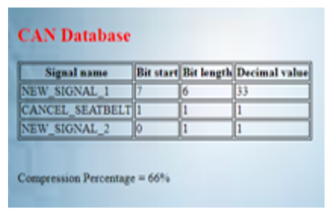
A text file known as a CAN DBC file (CAN database) contains instructions for translating raw CAN bus data into "physical. We have a file, which we have taken from the Open-source platform (Nissan leaf) that "extracts" parameters (signals) from the data bytes, we have a CAN DBC that has decoding rules for the CAN ID. Steer angle rate, Gas pedal inverted, and many more such signals. Figure 3, specifies how to decode CAN messages and signals at the core of a DBC file:
DBC message syntax explained
• The ID must be distinct and in decimal, and the message begins with BO_ (not hexadecimal).
• To act as an "extended ID" indication, the DBC ID adds three additional bits to 29-bit CAN IDs.
• The name should be distinct, 1-32 characters long, and allow for [A-z], numbers, and underscores.
• A number between 0 and 1785 must make up the length (DLC).
• The sender is the name of the transmitting node or, in the absence of a name, Vector XXX.
DBC signal syntax explained
• There are one or more signals that begin with SG_ in every message.
• The name may be up to 32 characters long, distinct, and may contain any combination of letters, digits, and underscores (a-z).
• Beginning with 0, the bit start signals the beginning of the signal in tqhe data payload.
• Signal length is equal to bit length.
• The @1 indicates the byte order.
• The plus symbol indicates that a value is unsigned (vs - for signed signals).
• The physical value linear equation uses the (scale, offset) values (more below).
• The receiving node's name is known as the receiver; once more, Vector XXX is used by default as shown in Figures 4 and 5.
Figure 3. DBC message and signal syntax
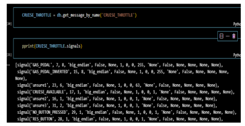
Figure 4. List of messages from the DBC file
Figure 5. List of signal from the DBC file
MQTT Cloud: MQTT is an OASIS standard messaging for IOT MQTT is utilized in many different industries today, including manufacturing, telecommunications, and the automobile sector. It utilizes one-to-one, one-to-many, and many-to-one communication mechanisms and has the highest overhead and QoS of TCP. The MQTT protocol is employed as a suitable protocol mechanism for the Internet of things and M2M claims. It makes use of a publish/subscribe protocol built for simple M2M protocol. An MQTT broker receives messages that an MQTT [30] client publishes and that other clients have subscribed to or have reserved for future subscriptions.
Benefits of using MQTT:
• Lightweight and efficient.
• Bi-directional communication.
• Reliable message delivery.
• Security enabled.
The widely used and well-supported Linux platform MQTT broker Mosquitto is simple to use. The cloud-based Mosquito [31] MQTT broker is in operation. As a result, it may receive messages from IoT devices everywhere. You can use that Cloud MQTT broker with many Telematics boards on various networks. To connect with the broker, each Telematics board needs to be attached to a router that provides internet access. The boards can communicate with one another by publishing and subscribing to the same topics because they use the same MQTT broker. You may have many IoT devices (such as ESP node MCU and Arduino Uno board) communicate with one another using a cloud MQTT broker even if they are on different networks by using a cloud based MQTT broker (different locations connected to different routers).
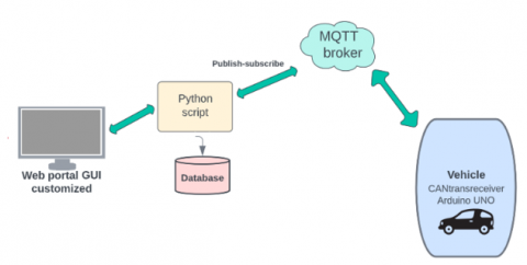
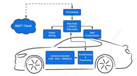
Figure 6 shows that we used Open DBC, a publicly accessible online database, as the baseline for evaluating our methodology. As previously indicated, it is challenging for researchers to secure a genuine DBC format because automobile makers keep them in strict confidence. One possible solution to this issue is Open DBC. SPI will be used to connect the CAN trans receiver to the Arduino, and CAN Hi/Low will be used to connect to the ECU. Using the software, we used a serial CAN trans receiver and Arduino to create an algorithm that transfers data to the cloud using the MQTT protocol. After transferring data and using an algorithm, compressed data will be shown in the GUI web application. In Figure 7, it shows the generalized system architecture of Raw data.
Figure 6. Integration between GUI design and hardware
Figure7. Generalized system architecture of cloud, raw data, and signals
Hardware Setup: The hardware configuration, shown in Figure 8, System Architecture consists of:
• Arduino uno (with external Wi-fi module connected).
• CAN trans receiver, the Arduino will be connected to the MCP2515 CAN-bus converter through the Serial Peripheral Interface (SPI).
• By using software, we use a serial CAN trans receiver and Arduino to create an algorithm that transfers data to the cloud using the MQTT protocol.
• After transferring data and using an algorithm, compressed data will be shown in the GUI web application.
Figure 8. Generalized system architecture of hardware
After the platform system experiment. The completed hardware setup is constructed, as shown in Figure 8. The Arduino UNO microcontroller will receive data in CAN communication from the ECU (Signal) via a CAN transceiver. SPI will be used to connect the CAN trans receiver to the Arduino, and CAN Hi/Low will be used to connect to the ECU. Data from the ECU will be in the form of a data packet, which will also include other data in hexadecimal format. Using the REST architectural technique and the Telematics Wi-Fi module, data obtained from the ECU will be sent to the cloud. By using software serial, the [32] MCP2515, and Arduino may create algorithms that transfer data using the MQTT protocol. For future works, this proposed system can be simulated in MATLAB & Simulink as this software by MathWorks has great capabilities [33, 34].
4.1 Hardware implementation
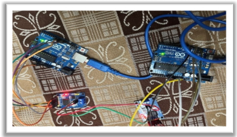
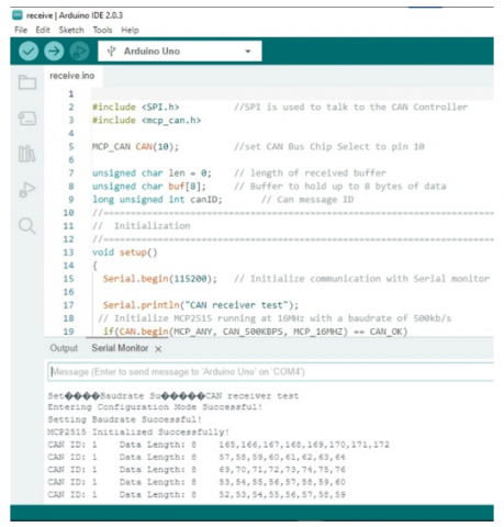
From the experiment, Creating the final hardware configuration is shown in Figure 9. We successfully used hardware implementation to send and receive CAN IDs and Data bytes. The outcome includes several CAN-bus data gathering, CAN-bus data conversion, and cloud-sending methods. There are some snapshots of the hardware module, which is shown in Figures 10 and 11. From this experiment, user interfaces (UI) for end users are also available, including web interfaces that include real-time data signals and UI provided by cloud storage providers. The experiment's output should resemble Figure 12 after completion. The outcome of data acquired from the ECU through CAN-bus is shown in the figure.
Figure 9. Hardware connection that consists of Arduino and CAN transreceiver
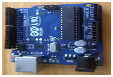
Figure 10. Arduino board connect with CAN bus converter
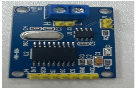
Figure 11. MCP2515 CAN-bus converter board
Figure 12. Output from Arduino and CAN transceiver
4.2 GUI design for web application using tool
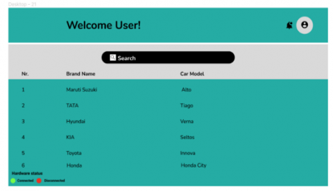
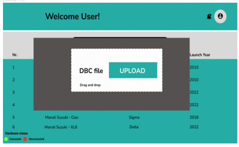
After Hardware implementation, our main objective is to free the user up to focus on the GUI. To give users an accessible and functional Web application, we used a tool. After entering the login credentials, the web program will provide a list of all vehicles along with their variants and the year they were released. The DBC text file will be requested for uploading in that web application, and after uploading, it will display a list of the messages and signals that are contained in the DBC file. Following the selection of signals, the real-time value of the vehicle for web design will be displayed.
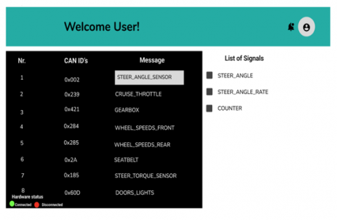
Figures 13, 14, 15, and 16 display the results of GUI design information obtained from the ECU and telematics via CAN-bus.
Figure 13. Welcome login page for a selection of vehicle
Figure 14. Upload DBC file
Figure 15. List of messages and signal
Figure 16. Real-time signal value from vehicle
The results of the experiment indicate that using an Arduino (with an external wi-fi module connected) and a CAN transceiver is the optimum method for gathering data from an ECU. Our study offers good end-to-end security and a compression ratio of up to 65-75% using the LZW compression method. This study provides real-time data visualization, reduces bandwidth needs, and effectively uses available bandwidth to lower costs per byte. We successfully developed a web application with a GUI for gathering signal data. We will upload data collected from the ECU to the cloud using a telematics Wi-Fi module. MCP2515 and Arduino developed algorithms that send data via the MQTT protocol by using software serial. We may enhance our research interests outside the automobile business to include sports medicine, healthcare, and many more. We employed the CAN database protocol for our research, but we might also use other protocols in the future, such as LIN or Ethernet.
[1] Berdigh, A., El Yassini, K. (2017). Connected car overview: Solutions, challenges and opportunities. In Proceedings of the 1st International Conference on Internet of Things and Machine Learning, pp. 1-7. https://doi.org/10.1145/3109761.3158382
[2] Darbha, S., Konduri, S., Pagilla, P.R. (2018). Benefits of V2V communication for autonomous and connected vehicles. IEEE Transactions on Intelligent Transportation Systems, 20(5): 1954-1963. https://doi.org/10.1109/TITS.2018.2859765
[3] Coppola, R., Morisio, M. (2016). Connected car: Technologies, issues, future trends. ACM Computing Surveys (CSUR), 49(3): 1-36. https://doi.org/10.1145/2971482
[4] Kim, Y., Oh, H., Kang, S. (2017). Proof of concept of home IoT connected vehicles. Sensors, 17(6): 1289. https://doi.org/10.3390/s17061289
[5] Yang, X., Sun, Z., Li, J., Yan, J., Li, T., Quan, W., Xu, D., Antichi, G. (2019). Fast: Enabling fast software/hardware prototype for network experimentation. In Proceedings of the International Symposium on Quality of Service, pp. 1-10. https://doi.org/10.1145/3326285.3329067
[6] Hossain, K., Roy, S. (2018). A data compression and storage optimization framework for iot sensor data in cloud storage. In 2018 21st International Conference of Computer and Information Technology (ICCIT), IEEE, pp. 1-6. https://doi.org/10.1109/ICCITECHN.2018.8631929
[7] Kavitha, P. (2016). A survey on lossless and lossy data compression methods. International Journal of Computer Science & Engineering Technology, 7(03): 110-114.
[8] Haque, M.J., Huda, M.N. (2017). Study on data compression technique. International Journal of Computer Applications, 159(5): 6-13.
[9] Fassak, S., El Idrissi, Y.E.H., Zahid, N., Jedra, M. (2017). A secure protocol for session keys establishment between ECUs in the CAN bus. In 2017 International Conference on Wireless Networks and Mobile Communications (WINCOM), November 01-04, 2017, Rabat, Morocco, IEEE, pp. 1-6. https://doi.org/10.1109/WINCOM.2017.8238149
[10] Mishra, B., Kertesz, A. (2020). The use of MQTT in M2M and IoT systems: A survey. IEEE Access, 8: 201071-201086. https://doi.org/10.1109/ACCESS.2020.3035849
[11] Sidna, J., Amine, B., Abdallah, N., El Alami, H. (2020). Analysis and evaluation of communication protocols for IoT applications. In Proceedings of the 13th International Conference on Intelligent Systems: Theories and Applications, pp. 1-6. http://dx.doi.org/10.1145/3419604.3419754
[12] Jansen, B.J. (1998). The graphical user interface. ACM SIGCHI Bulletin, 30(2): 22-26.
[13] Silva, T.R., Hak, J.L., Winckler, M., Nicolas, O. (2017). A comparative study of milestones for featuring GUI prototyping tools. Journal of Software Engineering and Applications, 10(6): 564-589.
[14] Moran, K., Bernal-Cárdenas, C., Curcio, M., Bonett, R., Poshyvanyk, D. (2018). Machine learning-based prototyping of graphical user interfaces for mobile apps. IEEE Transactions on Software Engineering, 46(2): 196-221. https://doi.org/10.1109/TSE.2018.2844788
[15] Moronfolu, D.O. (2009). An enhanced LZW text compression algorithm. Afr. J. Comp. & ICT, 2(2): 13-20.
[16] Bhattacharjee, A.K., Bej, T. and Agarwal, S. (2013). Comparison study of lossless data compression algorithms for text data. IOSR Journal of Computer Engineering (IOSR-JCE), 11(6): 15-19.
[17] Tukade, T.M., Banakar, R. (2018). Data transfer protocols in IoT—An overview. International Journal of Pure and Applied Mathematics, 118(16): 121-138.
[18] Singh, M., Rajan, M.A., Shivraj, V.L., Balamuralidhar, P. (2015). Secure mqtt for internet of things (IoT). In 2015 Fifth International Conference on Communication Systems and Network Technologies, IEEE, pp. 746-751. https://doi.org/10.1109/CSNT.2015.16
[19] Kumar, A., Ranjan, P., Saini, V. (2022). Smart irrigation system using IoT. In Agri-Food 4.0. Emerald Publishing Limited, Bingley, pp. 123-139. https://doi.org/10.1108/S1877-636120220000027009
[20] Hamid, A.F.A., Rahman, M.T.A., Khan, S.F., Adom, A.H., Rahim, M.A., Rahim, N.A., Ismail, M.H.N., Norizan, A. (2017). Connected car: Engines diagnostic via Internet of Things (IoT). Journal of Physics: Conference Series, 908(1): 012079. https://doi.org/10.1088/1742-6596/908/1/012079
[21] Behrang, F., Reiss, S.P., Orso, A. (2018). GUIfetch: Supporting app design and development through GUI search. In Proceedings of the 5th International Conference on Mobile Software Engineering and Systems, pp. 236-246. https://doi.org/10.1145/3197231.3197244
[22] Reuss, H.C. (1992). Extended frame format-a new option of the CAN Protocol. Product Concept & Application Laboratory Hamburg, FR Germany, HAI/AN, 92002.
[23] Choi, W., Lee, S., Joo, K., Jo, H.J., Lee, D.H. (2021). An enhanced method for reverse engineering CAN data payload. IEEE Transactions on Vehicular Technology, 70(4): 3371-3381. https://doi.org/10.1109/TVT.2021.3063261
[24] Kavousianos, X., Kalligeros, E., Nikolos, D. (2007). Multilevel Huffman coding: An efficient test-data compression method for IP cores. IEEE Transactions on Computer-Aided Design of Integrated Circuits and Systems, 26(6): 1070-1083. https://doi.org/10.1109/TCAD.2006.885830
[25] Bradley, S.D. (1969). Optimizing a scheme for run length encoding. Proceedings of the IEEE, 57(1): 108-109. https://doi.org/10.1109/PROC.1969.6899
[26] Moronfolu, D.O., Oluwade, D. (2009). An enhanced LZW text compression algorithm. Afr. J. Comp. & ICT, 2(2): 13-20.
[27] Vallerio, K.S., Zhong, L., Jha, N.K. (2006). Energy-efficient graphical user interface design. IEEE Transactions on Mobile Computing, 5(7): 846-859. https://doi.org/10.1109/TMC.2006.97
[28] Verma, M., Bridges, R., Hollifield, S. (2018). ACTT: Automotive CAN tokenization and translation. In 2018 International Conference on Computational Science and Computational Intelligence (CSCI), December 12-14, 2018, Vegas, NV, USA, IEEE, pp. 278-283. https://doi.org/10.1109/CSCI46756.2018.00061
[29] Choi, W., Lee, S., Joo, K., Jo, H.J., Lee, D.H. (2021). An enhanced method for reverse engineering CAN data payload. IEEE Transactions on Vehicular Technology, 70(4): 3371-3381. https://doi.org/10.1109/TVT.2021.3063261
[30] Manohar, H.L., Reuban Gnana Asir, T. (2018). Data consumption pattern of MQTT protocol for IoT applications. In Smart Secure Systems–IoT and Analytics Perspective: Second International Conference on Intelligent Information Technologies, Chennai, India, December 20-22, 2017, pp. 12-22, Springer, Singapore. https://doi.org/10.1007/978-981-10-7635-0_2
[31] Light, R.A. (2017). Mosquitto: server and client implementation of the MQTT protocol. Journal of Open Source Software, 2(13): 265. https://doi.org/10.21105/joss.00265
[32] Palomino, J., Cuty, E., Huanachin, A. (2021). Development of a CAN Bus datalogger for recording sensor data from an internal combustion ECU. In 2021 IEEE International Workshop of Electronics, Control, Measurement, Signals and their application to Mechatronics (ECMSM), June 21-22, 2021, Liberec, Czech Republic, IEEE, pp. 1-4. https://doi.org/10.1109/ECMSM51310.2021.9468837
[33] Saini, V., Shah, P., Sekhar, R. (2022). MATLAB and simulink for building automation. In 2022 IEEE Bombay Section Signature Conference (IBSSC), December 08-10, 2022, Mumbai, India, IEEE, pp. 1-6. https://doi.org/10.1109/IBSSC56953.2022.10037485
[34] Zhou, B., Chikkala, J., Schmitt, R. (2019). A load-adaptive and predictive control of energy-efficient building automation in production environment. Procedia CIRP, 79: 245-250. https://doi.org/10.1016/j.procir.2019.02.058