Subhash Tatale* | Vudatha Chandra Prakash
© 2022 IIETA. This article is published by IIETA and is licensed under the CC BY 4.0 license (http://creativecommons.org/licenses/by/4.0/).
OPEN ACCESS
Generation of test cases is one of the essential activities of the software testing process. The process of executing a programme to identify defects to improve the system's quality is known as software testing. Manually writing test cases takes time, effort, and money. On the other hand, generating test cases automatically is the solution to this problem. For this automation process, a model-based test case generation technique would be acceptable. A model is usually required to generate test cases in the model-based testing technique. Nowadays, researchers have relied on the activity diagram to generate test cases. Test cases for combinatorial logic systems are required. Combinatorial testing is essential for producing a small number of test cases and identifying errors occurred by interactions between system input parameters. Information about constraints, parameters and its values are required for generation of test cases. It is difficult to extract information regarding constraints, parameters, its values, and interactions between parameters from an Activity Diagram. A novel approach is proposed to extract this information from an Activity Diagram. The authors created a tool that automatically generates combinatorial test cases using UML Activity Diagrams. The proposed tool has two main parts. First, the combinatorial test design model is developed for extraction of input parameters. Second part is generation of optimized number of combinatorial test cases using Particle Swarm Optimization algorithm. Finally, the authors experimented on a real-world case study namely viz. Railway Reservation using the proposed tool, and it is shown that the proposed tool generated optimum number of combinatorial test cases.
covering arrays, combinatorial test case generation, behavioral UML diagrams, activity diagram, railway reservation system, concession management system, particle swarm optimization
Developing test cases during the design phase of the Software Development Life Cycle (SDLC) has significant advantages over the coding phase. The design models created can be used for generation of test cases during the design process. The generation of test cases from the design model assists in the early detection of flaws in the software development process. Even if we make a minor change to the code, the test cases developed during the design phase will still be valid [1]. It reduces testing time and cost dramatically. Unified Modelling Language (UML) models are simply graphical representations of software requirement specification documents. Test cases can be generated from UML diagrams. A final state, an initial state, constraints, and expected output comprise a test case, where constraints are pre and post conditions for the input values. It is challenging to extract information from a UML diagram, such as pre and post-conditions.
The solution to this problem includes pre-condition, post-condition, and system efficiency information in the design. As a result, test case generation from UML models is challenging [2].
Using UML Activity Diagrams, the various methodologies and techniques are used by many researchers to generate test cases automatically. Many systems use combinatorial logic, such as Tuition Fee Concession Subsystem, College Admission System, Concession Management SubSystem (CMSS) and so on. Combinatorial Testing (CT) is becoming very helpful to test such systems. Combinatorial testing has the significant advantage of reducing the number of test cases. As the number of test cases is reduced, the time required to execute those test cases is reduced. Additionally, test coverage has been increased (up to 100 per cent). As test coverage is increased, the product's quality improves. The increased coverage also increases the bug yield ratio. The overall cost of product testing is reduced.
The Combinatorial Test Design Model (CTDM) is widely used for generation of combinatorial test cases. Combinatorial test cases must be created for any system that requires combinatorial logic [3, 4].
Identifying the constraints, parameters and its values are the most difficult part of creating combinatorial test cases using Activity Diagram. Many times, an application will fail due to interaction between the application's input parameters. A pump, for example, may fail only when volume exceeds a certain amount and the pressure drops below a certain level, indicating a two-way interaction between volume and pressure. The code below shows how such a two-way interaction could occur. It should be noted that the failure will only occur if both pressure 100 are true. Without the other, neither of the conditions will be a problem.
if (pressure < 50) {
// do activity
if (volume >100) {
//wrong code
}
else {
//correct code
}
}
else {
// do activity
}
Identifying the values, parameters, and constraints by manually is error-prone and difficult task. Due to this, modelling these parameters is required to minimize the number of errors and improve the system quality. Combinatorial testing focuses on various parameter and value combinations [5]. A novel rule-based technique is provided for extraction of constraints, parameters, and its values from UML Activity Diagrams.
In the present research work, the authors proposed a technique for generating combinatorial test cases using the UML Activity Diagram. In the Test-Driven Development (TDD) model, test cases are to be developed before design and coding starts. In the case of systems that use combinatorial logic, our proposed work will be useful for generating combinatorial test cases. Similarly, in the case of Combinatorial Logic Oriented Acceptance Test-Driven Development (CLO-ATDD) model, customer has to generate User Acceptance Tests before the design and development starts. During the analysis phase, combinatorial test cases can also additionally be generated that are useful for CLO-ATDD model.
The authors presented a real-world case study i.e., Indian Railway Reservation System for generating combinatorial test cases in the current research. The results demonstrate that the proposed approach produces useful results. The concepts of Combinatorial Test Case Generation and UML Activity Diagram are described in the following section.
1.1 Combinatorial test case generation
For quality assurance of modern software systems, CT has become a vital and indispensable testing technique. CT has traditionally assumed that the input parameters of the Software under Test (SUT) are unrelated. However, input parameters of the system are frequently constrained in real world system. Such constraints may simply indicate that a particular interaction is not feasible in the test case (for example, in the concession management subsystem, a male passenger cannot avail “widow concession”) [6]. As a result, any CT application that fails to account for constraints may result in a large number of invalid test cases; CT may consequently be less effective than users would expect. The system inputs or configuration are modelled as sets of parameters and values in combinatorial testing; for each parameter (pi), a set of values (v1, v2,..., vn) is designed [7]. This methodology generates test cases by selecting a subset of the Cartesian product of all parameter values (based on some coverage criterion); a programme with five parameters, each with three values, has a total of 35 or 243 programme configurations.
For example, the car ordering application enables for the buying and selling of automobiles. It should be able to facilitate trade in Mumbai and Pune. The application should be able to trade Tata, Maruti, and Hundai automobiles. Input parameters and values of this application are shown in Table 1. To test all combinations of parameters and values, a total of 3*2*2 = 12 test cases are required.
Table 1. Input parameters and values
|
Values |
Parameters |
||
|
Car Product |
Order Category |
Payment Mode |
|
|
Tata |
Sell |
Online |
|
|
Maruti |
Buy |
Offline |
|
|
Hundai |
- |
- |
|
The test case size has been reduced from 12 to 6 in Table 2. The effectiveness of test cases can be validated by employing complex test input. For example, an input with ten parameters which are having ten values each. All combinations testing resulted in the creation of 1010 test cases. The number of test cases are reducing to 156 using pairwise testing.
Table 2. Generated test cases using 2-way testing techniques
|
Test Case Number |
Car Product |
Order Category |
Payment Mode |
|
1 |
Tata |
Sell |
Online |
|
2 |
Tata |
Buy |
Offline |
|
3 |
Maruti |
Sell |
Online |
|
4 |
Maruti |
Buy |
Offline |
|
5 |
Hundai |
Sell |
Online |
|
6 |
Hundai |
Buy |
Offline |
Designing the CTDM is an essential and significant pre-requisite for developing combinatorial test cases [8]. CTDM is made up of constraints, parameters, and its values that exist between them. Identifying parameters and values is a creative task which is not totally automated [9]. Because an activity diagram may be constructed from a high-level design to a low-level design, it is difficult to recognize CTDM elements from them. In complex systems, the number of parameters and its associated values are correspondingly large. Mixed Covering Arrays (MCA) and Covering Array (CA) are mathematical techniques to reduce test cases. CA(N; t; k; v) is a N x k array on v symbols in which each N x t sub-array includes at least one t-tuple from the v symbols. The parameters in CA have a fixed number of values whereas MCA have multiple different values of the parameters. A MCA (N; t; k; v1, v2,...,vn) is a N x k array on v symbols whose rows cover all t-tuples of value from the t columns at least once. The strength is referred to as t in CA and MCA, while the sample size is referred to as N. The parameter t specifies how actively to test the various configuration combinations. Pairwise interaction testing is used when t = 2.
1.2 Activity diagram
Activity diagrams are like traditional flowcharts but differ in the extra activities done by the system. Activity diagrams differ from flowcharts in that they can incorporate branching, parallel flow, swim lanes, and other features. To justify the diagram and its relevance, a thorough grasp of its main components is required. Knowing the main parts also aids in the correct development of the diagram. Following the identification of the activities, the following stage is to determine how they are related to limitations and circumstances.
The following key aspects should be identified before designing an activity diagram:
Activities
Association
Conditions
Constraints.
Once the pieces have been determined, an activity diagram is drawn using StarUML tool.
1.3 Railway reservation system – A case study
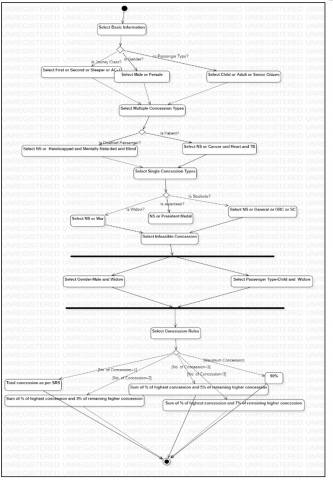
Indian Railways is one of the most recognized government organisations in India. The authors discussed the Indian Railway Reservation System's Concession Management SubSystem (CMSS) as a case study. Several concession categories like Senior Citizen, Child, Disabled Passenger, Patient, Student, Awardees, and War Widow are provided by Indian Railways. These concessions are available for a wide range of travel classes, including AC-I, Sleeper, First and Second Class. In the CMSS of Indian Railways, each concession category contains a variety of concession types.
Due to the large number of parameter and value combinations in the input, the number of combinatorial test cases generated for the journey class, concession categories, and their types may be enormous. The authors conducted a study on improving the ATDD Model using Combinatorial Logic. The authors [10] suggested a new Software Requirement Specification (SRS) for Indian Railways CMSS. When we apply an Exhaustive testing strategy to those concession parameters and values, we generate a total of 2x3x15x127x5x5x6x3x3x3x2 = 92583000 test cases. Generating and testing a huge number of test cases is difficult and impractical. Only a limited number of journey classes, concession categories, and types are considered to prevent a combinatorial explosion of test instances. Table 3 shows the different concession categories, types and percentage of concession as per the revised SRS of CMSS.
Figure 1 depicts UML Activity Diagram of Concession Management SubSystem as per considering revised SRS. The concession categories along with percentage of concession are considered.
The rest of the paper is structured as follows: Section 2 presents an overview of the related work. Section 3 outlines proposed work. Section 4 explains the experiments and evaluations of the proposed tool, while the conclusion and future scope is discussed in the section 5.
Table 3. Different concession categories, types and % of concession
|
Passenger Category |
Journey Class |
|||
|
First |
Second |
Sleeper |
AC-I |
|
|
Percentage of Concession |
||||
|
Patient |
||||
|
Cancer |
75 |
75 |
100 |
50 |
|
Heart |
75 |
75 |
75 |
50 |
|
TB |
75 |
75 |
75 |
50 |
|
Disabled Passenger |
||||
|
Mentally retarded |
75 |
75 |
75 |
50 |
|
Handicapped |
75 |
75 |
75 |
50 |
|
Blind |
75 |
75 |
75 |
50 |
|
Passenger Type |
||||
|
Senior Citizen |
50 |
50 |
50 |
50 |
|
Child |
50 |
50 |
50 |
50 |
|
Widow |
||||
|
War Widow |
50 |
50 |
75 |
0 |
|
Awardees |
||||
|
President Medal |
50 |
50 |
50 |
50 |
|
Student |
||||
|
General |
75 |
75 |
75 |
75 |
|
OBC |
50 |
50 |
50 |
50 |
|
SC |
25 |
25 |
25 |
25 |
Figure 1. Activity diagram of the revised CMSS
The authors provided an overview of the related work from the different perspectives, focusing on generation of test cases and the UML Activity Diagram-based combinatorial test design paradigm.
2.1 Generation of test cases from UML activity diagram
Many research articles are published by the researchers on generation of test case from Activity Diagrams using various approaches, like Graphical representation, Direct UML and formal specification, Heuristic, and Concurrent model.
Mu and Gu [11] presented a system test technique that employs formal specifications as well as the development of test coverage rules. Chen et al. [12] and Chen et al. [13] presented an approach to validate consistency between programme execution traces and behaviour. The authors suggested another technique to minimize validation efforts by lowering time of test case generation and needed test case size. As a result, meeting the functional coverage criterion is relatively simple. Teixeira and Braga e Silva [14] demonstrated a method to UML specification by presenting "Easy Test" tool based on the grey box approach.
Wang et al. [15] suggested the UMLTGF prototype tool, which was created using a grey box approach. Swain et al. [16] generated test sequences that met test adequacy criteria using Model Flow Graph (MFG) and Activity Flow Graph (AFG) as an intermediate model. Using the DFS method, all necessary information such as branches, conditions, executions, and loop expressions are retrieved. Samuel et al. [17] presented a dynamic slicing system that generates dynamic slices using an edge marking method. Each slice generates a set of test scenarios. Ray et al. [18] introduced a Flow Dependency Graph-based test case creation technique based on conditioned slicing.
Mingsong et al. [19] suggested an AGTCG prototype tool built with the DFS algorithm. This method verifies the correctness of requirements and accompanying programmes. As intermediate models, Boghdady et al. [20] and Boghdady et al. [21] employ Activity Dependency Table and Graph. By traversing graph with the Depth First Search method, all feasible test paths are produced. The test paths are automatically changed in the table to create the final test cases. Chouhan et al. [22] generated test cases using Activity Dependency Tables and Activity Dependency Graphs as intermediary methods.
Monim and Nor [23] presented a model-based testing technique for extracting, using, and preparing data from an Activity diagram for test case generation. Thanakorncharuwit et al. [24] presented a business flow constraint-based approach for test case generation. This paradigm employs several sets of rules for loop structures, as well as forks and joins. Hashim and Salman [25] proposed a more efficient technique of test case generation using an activity graph. Pechtanun and Kansomkeat [26] generated test cases using the Activity Convert grammar. Tiwari and Gupta [27] provided method for generating safety validation test cases using Software Fault and Software Success Tree.
To develop, optimise, validate, and prioritise test cases, Singla [28], Shanthi and MohanKumar [29] and Jena et al. [30] used Genetic algorithm. The test cases developed using these methodologies can be used to discover other errors such as synchronisation issues and loop faults. Nanda et al. [31] used a heuristic approach to choose the best test case from a set of existing path coverage. A heuristic rule is applied to the path coverage set after parsing an activity diagram. Shanthi et al. [32] employed the Tabu search approach to build, optimise, validate, and prioritise test cases from an activity diagram. To create an appropriate test path, Rhmann and Saxena [33] suggested Firefly algorithm. An Information Flow Metric is used to determine the adjacency measure of an activity graph. The proposed strategy is suitable for detecting system faults sooner. Arora et al. [34] developed concurrent test scenarios using a bio-inspired technique. The authors observed that the proposed bio-inspired technique performs better than the present genetic algorithm and ant colony optimization with respect to the size of test scenarios developed.
Oluwagbemi and Asmuni [35] used an activity diagram to create an Activity Flow Tree (AFT). To extract information from AFT, a parser is used. The activity sequences, related descriptions, and conditions of the constructed tree are used to produce test cases. By concentrating on the concurrency problem, Kamonsantiroj et al. [36] and Yimman et al. [37] created an activity graph. To create all the pathways from concurrent test cases, a dynamic programming method is used. This method satisfies the concurrent coverage criterion. The suggested technique's output is said to be more efficient than BFS and DFS methods.
Formal specification approach extracts information from SUT specifications rather than implementations. This approach is based on algebraic specifications. In the graphical representation approach, UML diagrams are transformed into tree or graph representations. These representations aid in the generation of test cases in a variety of ways. To generate test cases, various graph traversal methods and intermediate models are used. Several meta-heuristic techniques like simulated annealing, hill-climbing, genetic algorithm, tabu search, PSO, and others, can be used to generate optimized test cases. To exchange metadata information, the Object Management Group defined a standard process called XML Metadata Interchange (XMI). The use of XMI representations of UML models, parsers like Simple API of XML and Document Object Model has made direct processing of UML models easier. The Direct UML specification method generates test cases without the use of an intermediate model. In the Hybrid behaviour model approach, UML diagram may be used to obtain important information, followed by another UML diagram to obtain additional information to ensure that the generated test cases are complete. For example, an activity diagram may improve test-specific details derived from combined fragments of a Sequence diagram. A UML diagram can be used as input for a test case generation technique, and test cases can then be validated using another technique. Concurrent models are commonly used in mission-critical systems. The objective of this approach is to generate test suites that meet concurrency coverage criteria. Concurrent execution behaviour is provided in UML Sequence and Activity diagrams via concurrent asynchronous messages and fork-join constructs.
2.2 Combinatorial test design model
This section covers relevant research on the combinatorial test design model. In the combinatorial testing technique [38], a Neural Network approach [39] enhances combinatorial coverage. Multi-objective crow search and Fruit-fly optimization algorithms generates optimized number of combinatorial test cases in a constraints-handling setting [40]. Combinatorial test cases are generated from safety-critical embedded systems to check that the greater number of output combinations are appropriately investigated. A genetic algorithm is used to produce these test conditions [41, 42].
The combinatorial logic-oriented test case generation from UML artefacts is essential. Subhash Tatale and Prakash [43] conducted a review for generating test case from Sequence and Activity diagrams and presented technique for improving the ATDD model using combinatorial logic. To extract parameters and values, Esfandyari and Rafe [44] utilized model checking approaches. The directed graph is generated from the states of the system using this approach. Satish and Rangarajan [45] and Satish et al. [46] suggested a semi-automated rule-based technique to obtaining combinatorial test design model information. Bangare et al. and Pande et al. [47-52] have proposed object-oriented metrics for software quality measurement. Tatale et al. [53, 54] presented different approaches for generating combinatorial test cases using sequence diagram.
It takes time and effort to identify the exact number of constraints, parameters, and its values from UML diagrams manually. The authors described a method for extracting preparatory information from the Activity Diagram, such as constraints, parameters, and values. Combinatorial logic is used to generate combinatorial test cases from the extracted information.
The authors proposed Combinatorial Test Case Generator (CTCG) tool for generating combinatorial test cases. A model is created using StarUML as per the system requirements and CTDM elements are produced. To extract information from CTDM, a multi-stage algorithm is used.
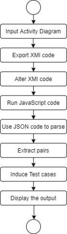
As an input to the proposed system, a test manager will provide Activity Diagram. The constraints, parameters and its values are derived from the Activity Diagram. The derived parameters and values are used to generate parameter and value combinations. The constraints are applied to list that is generated by combinatorial process. Following that, rules based on combinatorial logic are applied to generate combinatorial test cases. The activity diagram of the proposed CTCG tool is depicted in Figure 2.
Figure 2. Flow chart of CLTG tool
3.1 Extraction of CTDM elements from activity diagram
The steps to extract CTDM elements like parameters, their associated values and constraints are explained in this section.
3.1.1 Export XMI code
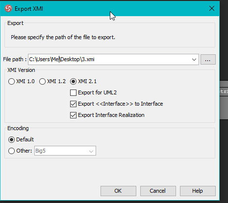
In the mentioned application, StarUML is used to draw an activity diagram and to export the XMI code corresponding to the same. StarUML is an advanced software modeller that aims to support agile and concise modelling. StarUML has XMI export as its key feature and support to import and export XMI (XML Metadata Interchange) which makes it more useful software. It is based on XMI 2.1 and UML 2.0 meta model. XMI is for metadata interchange among various software modeling tools.
Figure 3. XMI code generation in StarUML
The XMI code is generated in following ways in the StarUML. The Figure 3 shows the screen of StartUML tool for exporting XMI.
Select the menu: File > Export > XMI Export (v2.1).
3.1.2 Understanding the XMI
XMI defines few tags and attributes. The root element is always XMI. It must include the xmi.version property.
XMI.header is a placeholder for model information. The most significant of its descendants are XMI.metamodel and XMI.documentation.
XMI.content contains the actual model.
XMI.metamodel records the metamodel to which the XMI algorithm has been applied.
XMI.documentation holds end-user information as these children elements whose names are self-explanatory:
XMI.notice
XMI.exporterID
XMI.exporterVersion
XMI.exporter
XMI.contact
XMI.shortDescription
XMI.longDescription
XMI.owner.
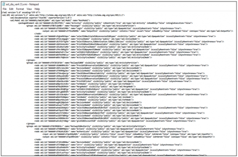
The attributes xmi.idref and xmi.id are used to encode connections. xmi.idref is a reference to an element by its identifier, and xmi.id is a unique element identification. The Figure 4 depicts the snapshot of XMI code of the application.
Figure 4. XMI code for the mentioned application
3.1.3 Alter the XMI code
It is necessary to group the tags under the same tag to get access of all of them to make is more reachable. The minor changes that are done are quite visible in the further screenshot of the modified XMI code. JavaScript code consists of an function called the parameterValusMapping() function. By using this function, the parameters and their associated values are extracted. The steps of the algorithm show the extraction of constraints, parameters, and values. XMI code is given as an input to this algorithm.
Step 1: Mark parameter “p” to the node with xmi:type = uml: OpaqueAction.
Step 2: Get the xmi:id of that node.
Step 3: Traverse the edges_array and find the edge withxmi:id of node = source of edge.
Step 4: Consider target of that edge.
Step 5: Again, traverse the edge_array, and find all the edges such that target of edge = source of edges. Collect ‘name’ attribute of all matching nodesand push into ‘v’.
Step 6: The 'v' array contains all the values of corresponding parameter.
Step 7: push 'p' and 'v' in finalConfig array.
Step 8: Repeat till all the XMI tags are covered.
Output: Extracted parameters, values and constraints.
3.1.4 Conversion of XMI to JSON using JavaScript
JSON stands for JavaScript Object Notation. It is necessary to convert XML code into JSON code in order to make use of the feature of JSON of preserving the code in pairs. It helps to deliver the output in the required format. The below JavaScript code converts defined XMI code to JSON code.
|
constconvertXMITOJSON = ( ) => { return new Promise((resolve, reject) => { xml2json( { input: "./test.xmi", output: "./check.json", }, function (error, output) { if (error) { console.error(error); reject(error); } else { resolve(output); } } ); }); }; |
3.1.5 Parse the JSON code
JSON is an incredibly lightweight syntax of data transmission between server and client which is simple and rapid to scan and create. It is a text-based syntax which is easy for both machines and humans to produce and understand; however, unlike XML, JSON data structures require less bandwidth than their XML counterparts.
With the aid of Java-script, JSON data received from the web server may be readily processed using the JSON.parse() function. This function parses JSON string and returns the JavaScript object. Syntax errors will be displayed if the provided string is not in the specified JSON format.
This JavaScript object is used to convert JSON string into a JavaScript object and access individual values using the dot notation (.). All parameter-value pairs are saved in.csv files, which are extracted via the JSON file. The output in the form of pairs of parameters and values is displayed on the console. Table 4 depicts extracted parameter-value pairs which are extracted from UML Activity Diagram.
As per Activity Diagram shown in Figure 1, the Patient and Disabled passenger categories have multiple selection options. It indicates that multiple value combinations are chosen for the Patient and Disabled Passenger parameters. As a result, an AC test cases provides N-wise coverage.
Values for All combination = ∑ 2v, where v is number of values.
All combination values for Patient and Disabled passenger parameters are as below:
All Combinations value (Patient) = {NS, Heart, Cancer, TB, Heart and Cancer, TB and Cancer, TB and Heart, Heart and Cancer and TB}.
All combination value (Disabled Passenger) = {NS, Blind, Handicapped, Mentally Retarded, Mentally Retarded and Handicapped, Handicapped and Blind, Mentally Retarded and Blind, Retarded and Handicapped and Blind}.
Table 4. Extracted parameter-value pairs
|
Parameters |
Type of Input |
No. of Value |
Values |
|
Journey Class |
Compulsory and Mutually Exclusive |
4 |
First, Second, Sleeper, AC-I |
|
Gender |
Compulsory and Mutually Exclusive |
2 |
Male, Female |
|
Passenger Type |
Compulsory and Mutually Exclusive |
3 |
Child, Adult, Senior Citizen |
|
Awardees |
Optional and Mutually Exclusive |
2 |
NS, President Medal |
|
Disabled Passenger |
Optional and All Combinations |
8 |
NS, Handicapped, Mentally Retarded, Blind |
|
Patient |
Optional and All Combinations |
8 |
NS, Cancer , Heart , TB |
|
Widow |
Optional and Mutually Exclusive |
2 |
NS, War |
|
Student |
Optional and Mutually Exclusive |
4 |
NS, General, OBC, SC |
Table 5. Extracted constraints
|
S. N. |
Concession Categories |
Concession types |
Invalid concession categories |
|
1 |
Passenger type |
Child |
Widow |
|
2 |
Gender |
Male |
Widow |
Table 6. Combinatorial logic-oriented concession rules
|
Rule No. |
1 |
2 |
3 |
4 |
5 |
|
Criteria |
No. of concession types selected= 1 |
No. of concession types selected= 2 |
No. of concession types selected= 3 |
No. of concession types selected > 3 |
% of total concession exceeds maximum allowed concession |
|
Total concession (in %) |
% Of total concession is applicable as per Table 3. |
% Of total concession = % of highest concession type + 5% of remaining concession type |
% Of total concession = % of highest concession type + 7% of remaining higher concession type |
% Of total concession = % of highest concession type + 10% of highest of the remaining concession type |
% Of total concession = maximum allowed concession (=100%) |
Table 7. Generated test cases using all combination strategy
|
TC No. |
Journey class |
Gender |
Passenger type |
Awardees |
Disabled passenger |
Patient |
Widow |
Student |
Expected concession (%) |
|
1 |
First |
Male |
Child |
NS |
NS |
NS |
NA |
NS |
50 |
|
2 |
First |
Male |
Child |
NS |
NS |
NS |
NA |
General |
50.75 |
|
. . . |
. . . |
. . . |
. . . |
|
. . . |
. . . |
. . . |
|
. . . |
|
16383 |
AC-I |
Female |
Senior Citizen |
President Medal |
Handicapped and Mentally Retarded and Blind |
TB and Heart and Cancer |
NS |
OBC |
56.18 |
|
16384 |
AC-I |
Female |
Senior Citizen |
President Medal |
Handicapped and Mentally Retarded and Blind |
Cancer and Heart and TB |
War |
SC |
78.68 |
The constraints values are identified in the diagram using fork and join synchronization bar in the activity diagram. The infeasible combinations of parameters and values are shown in Table 5.
The combinatorial logic rules are extracted from the JSON file which are shown in Table 6.
3.2 Combinatorial test case generation techniques
In this section, the authors proposed Pairwise Testing and All Combinations techniques for the generation of combinatorial test cases. The PSO algorithm is used to generate optimal pairwise test cases. In the construction of combinatorial test cases, combinatorial logic-oriented rules, constraints, parameters and its associated values are critical. The test cases in the preceding section were generated using All Combinations and the pairwise testing technique.
3.2.1 All Combinations (AC) testing technique
The AC testing technique generates every possible parameter value combination. This method generates all possible discrete parameter and value combinations. The authors extracted parameters and values from the CMSS. As shown in Table 4, the authors extracted eight parameters.
Number of test case combinations as per extracted parameters shown in Table 4.
= 4x2x3x2x8x8x2x4=24576 --------------(I)
The below are the invalid combinations of parameters and values: -
Child - Widow
Male - Widow
The redundant test cases are removed because of NS (Not Selected) and NA (Not Applicable) value of parameters.
The redundant test combinations generated because of invalid combinations of Child and Widow.
= 4x2x1x2x8x8x1x4= 4096 -------------(II)
The redundant test combinations because of invalid combinations of Male and Widow.
= 4x1x2x2x8x8x1x4= 4096 -------------(III)
Total redundant test combinations because of invalid combinations.
= 4096+4096 (From Eq.II, and III) = 8192 --------(IV)
Total distinct test combinations= 24576-8192 (from Eq. I and IV) = 16384.
As a result, using All Combinations technique, a total of 16384 test cases are generated from the Activity Diagram which are shown in Table 7. The expected concession in percentage is calculated as per combinatorial logic-oriented rules which are shown in Table 6.
These test cases also covers the constraints of parameter-value combinations. All invalid combinations are shown in the test case by a 'NA' value. For smaller parameter and value sizes, the all combinations testing strategy works well. It is a very time-consuming task to generating test cases using all combinations techniques for large number of input parameters and values. As a result, the number of test cases should be reduced while maintaining coverage. Pairwise testing is much faster than all combinations testing, which tests all possible combinations of all input parameters. Chandra Prakash and Kadiyala Priyanka [55] and Kondhalkar and ChandraPrakash [56] proposed pairwise plus testing strategy for generating combinatorial test cases.
3.2.2 Pairwise technique using PSO algorithm
Poli et al. [57] introduced the PSO algorithm, which is based on social behaviour observed in flocks of birds. A swarm is refered as the entire search space whereas a particle is refered as a single member of the search space. Each particle represents a single solution. Each particle has a velocity, which aids in navigating the multidimensional search space. This velocity provides a direction for travelling toward an approximate solution to the specified goal function. The fitness value of each particle is calculated by the fitness function. Chen et al. [58] proposed the PSO algorithm for generating combinatorial test cases. Bewoor et al. [59-61] used PSO algorithm to solve combinatorial optimization problem of No Wait Flow Shop Scheduling (NWFSSP). Chandraprakash et al. [62] surveyed various PSO variant algorithms. One of the PSO variant algorithms works as follows. The number of parameters, values and constraints are given as input to the algorithm. The below are the steps for generating combinatorial test cases using PSO algorithm.
1. Generate a set P of all unexplored pair combinations of parameter and values;
2. Initialise particles randomly with random velocities and positions.
3. while set P of pairs is not empty.
4. Assess the coverage of pair combinations using fitness function.
5. Select the particle with greatest coverage.
6. Determine the particles' fitness value.
7. Determine each particle's global best (gbest) and personal best (pbest).
8. Remove from set P all pairings that are covered by the best particle.
9. Update velocity according to Eq. (1).
10. Update position according to Eq. (2).
11. Repeat steps 4–9 until step 3 is satisfied.
Table 8. Generated test cases using particle swarm optimization
|
TC No. |
Journey class |
Gender |
Passenger type |
Awarsssdees |
Disabled passenger |
Patient |
Widow |
Student |
Expected concession (%) |
|
1 |
Sleeper |
Male |
Child |
NS |
NS |
NS |
NA |
NS |
50 |
|
2 |
AC-I |
Male |
Adult |
President Medal |
Mentally Retarded and Blind |
Cancer and TB |
NA |
OBC |
55.11 |
|
. . . |
|
. . . |
. . . |
. . . |
. . . |
. . . |
. . . |
|
. . . |
|
74 |
First |
Female |
Adult |
NS |
Blind |
Cancer and Heart and TB |
NS |
SC |
82.5 |
|
75 |
Sleeper |
Female |
Adult |
President Medal |
Handicapped and Blind |
Cancer and Heart |
War |
General |
100 |
The particles are initialized at random locations initially, and then they explore the search space by changing their positions in order to find a better solution. After each iteration, each particle changes its velocity to follow one of the two best possibilities. By maintaining its current velocity and position, each particle indicates a possible solution. Swarm keeps track of global best (gbest) and personal best (pbest) in addition to their unique solutions. To explore solution space, the position and velocity are changed repeatedly. The exploitation was considered by locating potential neighbours and is heavily reliant on the values of gbest and pbest. The termination criteria for this iterative technique are dependent on the maximum number of iterations and swarm convergence. To change the particle's position and velocity in the search space, various update criteria are used. Each particle velocity is adjusted based on the aforementioned algorithm for improved mobility throughout the search space. This updated velocity is used to determine the new position of the particles.
Eq. (1) indicates rule for the velocity updating of particles.
$\operatorname{Vel}_{i, d}(n)=w V e l_{i, d}(n-1)+c 1 r 1_{i, d}\left(g b e s t_{i, d}(n-1)-\operatorname{Pos}_{i, d}(n-1)\right)+c 2 r 2_{i, d}\left(p b e s t_{i, d}(n-1)-P o s_{i, d}(n-1)\right)$ (1)
Eq. (2) shows rule of updating of position of particles.
$\operatorname{Pos}_{i, d}=X-\operatorname{Pos}_{i, d}(n-1)+V e l_{i, d}(n)$ (2)
where, n denotes the number of iterations, i denotes the particle index and d is the dimension. w is the weight factor for inertia, r1 and r2 are random values, acceleration coefficients (c1 and c2) are used to alter the inertia weight.
The PSO method was applied to the inputs generated by Figure 1. The pairs are created using the input 23314282. The activity diagram generates a total of 75 test cases, resulting in a 100% coverage criterion. Table 8 displays the test cases created by PSO.
The authors developed CTCG tool to generate combinatorial test cases from an activity diagram to expedite and improve the testing process. The authors provided Pairwise Testing and All Combinations techniques for creating combinatorial test cases from an activity diagram. PSO algorithm is used to generate optimal combinatorial test cases. The input 23314282 shows that three parameters with two values, one with three values, two with eight values, and two with four values. The accuracy percentage denotes the proportion of pairs covered by the test cases that were created. Using All Combinations techniques, a total of 16384 test cases are generated. This strategy generates all possible input parameter combinations. Combinatorial explosion occurs when the number of input parameters is extremely large. To avoid the problem of combinatorial explosion, the pairwise testing technique is used. The pairs of input parameters are generated during pairwise testing. As mentioned in section 3.2.2, the PSO algorithm generates test cases. This algorithm will continue to run until all of the pairs have been covered. Using the pairwise and PSO algorithms, a total of 75 test cases are generated. 100% accuracy means all the pairs generated for the input 23314282 are covered by those 75 test cases. Table 9 displays the outcomes of the proposed approach.
Table 9. Summary of the results
|
Sr. No. |
Input size |
Techniques used |
No. of test cases generated |
Accuracy (%) |
|
1 |
23314282 |
All Combinations |
16384 |
100 |
|
2 |
23314282 |
Pairwise & Particle Swarm Optimization |
75 |
100 |
The authors demonstrated how to generate combinatorial test cases using a UML Activity Diagram. The authors demonstrated a two-stage method for extracting constraints, parameters, and values from UML Activity Diagrams. The various combined fragments, actions, and activity states are used to identify constraints, parameters and values.
The proposed Combinatorial Test Case Generation Tool is used to generate combinatorial test cases from an Activity Diagram. The All-Combinations method ensures complete coverage but has a greater number of test cases. Constructing combinatorial test cases using the All-Combinations technique is difficult and time consuming. However, in terms of size of test cases, the PSO algorithm gives better results than the All-Combinations technique.
The suggested approach produces combinatorial test cases from constraints, parameters, and its values extracted from the Activity Diagram, whereas previous approaches generate test cases from transition, activity, simple and concurrent paths, and so on.
The proposed technique for generating combinatorial test cases from UML Activity Diagrams can be particularly useful for TDD and CLO-ATDD models. If certain systems are built on Combinatorial Logic and developed using the TDD approach, the presented work will be highly valuable to such systems in order to produce combinatorial test cases. The authors claimed that the proposed tool is extremely efficient and reliable.
In the future, the different techniques can be proposed to extract CTDM information to generate combinatorial test cases from other UML diagrams like State Chart Diagram.
[1] Hartmann, J., Vieira, M., Foster, H., Ruder, A. (2005). A UML-based approach to system testing. Innovations in Systems and Software Engineering, 1(1): 12-24. https://doi.org/10.1007/s11334-005-0006-0
[2] Briand, L., Labiche, Y. (2002). A UML-based approach to system testing. Software and Systems Modeling, 1(1): 10-42. https://doi.org/10.1007/s10270-002-0004-8
[3] Nebut, C., Fleurey, F., Le Traon, Y., Jezequel, J.M. (2006). Automatic test generation: A use case driven approach. IEEE Transactions on Software Engineering, 32(3): 140-155. https://doi.org/10.1109/TSE.2006.22
[4] Grindal, M., Offutt, J., Andler, S. F. (2005). Combination testing strategies: A survey. Software Testing, Verification and Reliability, 15(3): 167-199. https://doi.org/10.1002/stvr.319
[5] Kuhn, R., Lei, Y., Kacker, R. (2008). Practical combinatorial testing: Beyond pairwise. It Professional, 10(3): 19-23. https://doi.org/10.1109/MITP.2008.54
[6] Kuhn, D.R., Kacker, R.N., Lei, Y. (2010). Practical combinatorial testing. NIST Special Publication, 800(142): 142. https://doi.org/10.1109/MITP.2008.54
[7] Kuhn, D.R., Bryce, R., Duan, F., Ghandehari, L.S., Lei, Y., Kacker, R.N. (2015). Combinatorial testing: Theory and practice. Advances in Computers, 99: 1-66. https://doi.org/10.1016/bs.adcom.2015.05.003
[8] Lott, C., Jain, A., Dalal, S. (2005). Modeling requirements for combinatorial software testing. ACM SIGSOFT Software Engineering Notes, 30(4): 1-7. https://doi.org/10.1145/1082983.1083281
[9] Nie, C., Leung, H. (2011). A survey of combinatorial testing. ACM Computing Surveys (CSUR), 43(2): 1-29. https://doi.org/10.1145/1883612.1883618
[10] Tatale, S.B., Prakash, V.C. (2020): Enhancing acceptance test driven development model with combinatorial logic. International Journal of Advanced Computer Science and Applications (IJACSA), 11(10): 268-278. https://doi.org/10.14569/IJACSA.2020.0111036
[11] Mu, K., Gu, M. (2006). Research on automatic generating test case method based on UML activity diagram. Journal of Computer Applications, 4(3): 15-22.
[12] Chen, M., Qiu, X., Xu, W., Wang, L., Zhao, J., Li, X. (2009). UML activity diagram-based automatic test case generation for Java programs. The Computer Journal, 52(5): 545-556. https://doi.org/10.1093/comjnl/bxm057
[13] Chen, M., Mishra, P., Kalita, D. (2010). Efficient test case generation for validation of UML activity diagrams. Design Automation for Embedded Systems, 14(2): 105-130. https://doi.org/10.1007/s10617-010-9052-4
[14] Teixeira, F.A.D., Braga e Silva, G. (2018). EasyTest: An approach for automatic test cases generation from UML activity diagrams. In Information Technology-New Generations, pp. 411-417. https://doi.org/10.1007/978-3-319-54978-1_54
[15] Wang, L.Z., Yuan, J.S., Yu, X.F., Hu, J., Li, X.D., Zheng, G.L. (2004). Generating test cases from UML activity diagram based on gray-box method. In 11th Asia-Pacific Software Engineering Conference, pp. 284-29. https://doi.org/10.1109/APSEC.2004.55
[16] Swain, R.K., Panthi, V., Behera, P.K. (2013). Generation of test cases using activity diagram. International Journal of Computer Science and Informatics, 3(2): 1-10. https://doi.org/10.47893/IJCSI.2014.1172
[17] Samuel, P., Mall, R. (2009). Slicing-based test case generation from UML activity diagrams. ACM SIGSOFT Software Engineering Notes, 34(6): 1-14. https://doi.org/10.1145/1640162.1666579
[18] Ray, M., Barpanda, S.S., Mohapatra, D.P. (2009). Test case design using conditioned slicing of activity diagram. International Journal of Recent Trends in Engineering, 1(2): 117.
[19] Chen, M.S., Qiu, X.K., Li, X.D. (2006). Automatic test case generation for UML activity diagrams. In Proceedings of the 2006 International Workshop on Automation of Software Test, pp. 2-8.
[20] Boghdady, P.N., Badr, N.L., Hashem, M., Tolba, M.F. (2011). A proposed test case generation technique based on activity diagrams. International Journal of Engineering & Technology IJET-IJENS, 11(3): 1-21.
[21] Boghdady, P.N., Badr, N.L., Hashim, M.A., Tolba, M.F. (2011). November. An enhanced test case generation technique based on activity diagrams. In The 2011 International Conference on Computer Engineering & Systems, pp. 289-294.
[22] Chouhan, C., Shrivastava, V., Sodhi, P.S. (2012). Test case generation based on activity diagram for mobile application. International Journal of Computer Applications, 57(23):4-9. http://dx.doi.org/10.5120/9436-3563
[23] Monim, M.A., Nor, R.N.H. (2018). An automated test case generating tool using UML activity diagram. International Journal of Engineering & Technology, 7(4.31): 58-63. http://dx.doi.org/10.14419/ijet.v7i4.31.23342
[24] Thanakorncharuwit, W., Kamonsantiroj, S., Pipanmaekaporn, L. (2016). Generating test cases from UML activity diagram based on business flow constraints. In Proceedings of the Fifth International Conference on Network, Communication and Computing, pp. 155-160. https://doi.org/10.1145/3033288.3033311
[25] Hashim, N.L., Salman, Y.D. (2011). An improved algorithm in test case generation from UML activity diagram using activity path. In: 3rd International Conference on Computing and Informatics (ICOCI 2011), pp. 226-231.
[26] Pechtanun, K., Kansomkeat, S. (2012). Generation test case from UML activity diagram based on AC grammar. In 2012 International Conference on Computer & Information Science (ICCIS), 2: 895-899. https://doi.org/10.1109/ICCISci.2012.6297153
[27] Tiwari, S., Gupta, A. (2013). An approach to generate safety validation test cases from UML activity diagram. In 2013 20th Asia-Pacific Software Engineering Conference (APSEC), 1: 189-198. https://doi.org/10.1109/APSEC.2013.35
[28] Singla, I., Amandeep, Pratibha. (2015). A semantic approach for the generation of test cases from activity diagram. International Journal of Computer Applications, 116(10): 12-16.
[29] Shanthi, A.V.K., MohanKumar, G. (2012). A novel approach for automated test path generation using tabu search algorithm. International Journal of Computer Applications, 48(13): 28-34. http://dx.doi.org/10.5120/7410-0449
[30] Jena, A.K., Swain, S.K., Mohapatra, D.P. (2014). A novel approach for test case generation from UML activity diagram. In 2014 International Conference on Issues and Challenges in Intelligent Computing Techniques (ICICT), pp. 621-629. http://dx.doi.org/10.1109/ICICICT.2014.6781352
[31] Nanda, P., Biswal, B.N., Mohapatra, D.P. (2008). A novel approach for test case generation using activity diagram. International Journal of Computer Science and Applications, 1(1): 60-63.
[32] Shanthi, A.V.K., Kumar, G.M. (2012). A heuristic technique for automated test cases generation from UML activity diagram. I-Manager's Journal on Software Engineering, 6(3): 13. http://dx.doi.org/10.26634/jse.6.3.1787
[33] Rhmann, W., Saxena, V. (2016). Optimized and prioritized test paths generation from UML activity diagram using firefly algorithm. International Journal of Computer Applications, 145(6): 16-22. http://dx.doi.org/10.5120/ijca2016910718
[34] Arora, V., Bhatia, R., Singh, M. (2017). Synthesizing test scenarios in UML activity diagram using a bio-inspired approach. Computer Languages, Systems & Structures, 50: 1-19. https://doi.org/10.1016/j.cl.2017.05.002
[35] Oluwagbemi, O., Asmuni, H. (2015). Automatic generation of test cases from activity diagrams for UML based testing (UBT). Jurnal Teknologi, 77(13): 37-48. http://dx.doi.org/10.11113/jt.v77.6358
[36] Kamonsantiroj, S., Pipanmaekaporn, L., Lorpunmanee, S. (2019). A memorization approach for test case generation in concurrent UML activity diagram. In Proceedings of the 2019 2nd International Conference on Geoinformatics and Data Analysis, pp. 20-25. https://doi.org/10.1145/3318236.3318256
[37] Yimman, S., Kamonsantiroj, S., Pipanmaekaporn, L. (2017). Concurrent test case generation from UML activity diagram based on dynamic programming. In Proceedings of the 6th International Conference on Software and Computer Applications, pp. 33-38. https://doi.org/10.1145/3056662.3056699
[38] Ramgouda, P., Chandraprakash, V. (2018). Neural network-based approach for improving combinatorial coverage in combinatorial testing approach. Journal of Theoretical and Applied Information Technology, 20(96): 6677-6687.
[39] Gouda, R., Chandraprakash, V. (2019). Optimization driven constraints handling in combinatorial interaction testing. International Journal of Open Source Software and Processes (IJOSSP), 10(3): 19-37. https://doi.org/10.4018/IJOSSP.2019070102
[40] Ramgouda, P., Chandraprakash, V. (2019). Constraints handling in combinatorial interaction testing using multi-objective crow search and fruitfly optimization. Soft Computing, 23(8): 2713-2726. https://doi.org/10.1007/s00500-019-03795-w
[41] Vudatha, C.P., Nalliboena, S., Jammalamadaka, S.K., Duvvuri, B.K.K., Reddy, L.S.S. (2011). Automated generation of test cases from output domain of an embedded system using Genetic algorithms. In 2011 3rd International Conference on Electronics Computer Technology, 5: 216-220. https://doi.org/10.1109/ICECTECH.2011.5941989
[42] Vudatha, C.P., Jammalamadaka, S.K., Duvvuri, B.K.K. (2011). Automated generation of test cases for testing critical regions of embedded systems through adjacent pair-wise testing. IOT based Test Bed, 2(2): 10-15. https://doi.org/10.1007/978-3-642-01653-0_5
[43] Tatale, S.B., Prakash, V.C. (2021). A survey on test case generation using UML diagrams and feasibility study to generate combinatorial logic oriented test cases. International Journal of Next-Generation Computing, 12(2). https://dx.doi.org/10.47164/ijngc.v12i2.781
[44] Esfandyari, S., Rafe, V. (2020). Extracting combinatorial test parameters and their values using model checking and evolutionary algorithms. Applied Soft Computing, 91: 106219. https://doi.org/10.1016/j.asoc.2020.106219
[45] Satish, P., Rangarajan, K. (2016). A preliminary survey of combinatorial test design modeling methods. International Journal Of Scientific Engineering Research, 7(7): 1455-1459.
[46] Satish, P., Sheeba, K., Rangarajan, K. (2013). Deriving combinatorial test design model from UML activity diagram. In 2013 IEEE Sixth International Conference on Software Testing, Verification and Validation Workshops, pp. 331-337. https://doi.org/10.1109/ICSTW.2013.44
[47] Bangare, S.L., Bangare, P.S. (2012). Automated testing in development phase. International Journal of Engineering Science and Technology, 4(2): 677-680.
[48] Bangare, S.L., Borse, S., Bangare, P.S., Nandedkar, S. (2012). Automated API testing approach. International Journal of Engineering Science and Technology, 4(2): 673-676.
[49] Bangare, S.L., Khare, A.R., Bangare, P.S. (2010). Code parser for object oriented software modularization. International Journal of Engineering Science and Technology, 2(12): 7262-7265.
[50] Bangare, S.L., Khare, A.R., Bangare, P.S. (2011). Quality measurement of modularized object-oriented software using metrics. In Proceedings of the International Conference & Workshop on Emerging Trends in Technology, pp. 771-774. https://doi.org/10.1145/1980022.1980190
[51] Bangare, S.L., Khare, A.R., Bangare, P.S. (2011). Measuring the quality of Object-oriented software Modularization: Defining metrics and algorithm. International Journal on Computer Science and Engineering, 3(1): 445-450.
[52] Pande, S.D., Patil, U.A., Chinchore, R., Chetty, M.S.R. (2019). Precise approach for modified 2 stage algorithm to find control points of cubic Bezier curve. In 2019 5th International Conference on Computing, Communication, Control and Automation (ICCUBEA), pp. 1-8. https://doi.org/10.1109/ICCUBEA47591.2019.9128550
[53] Tatale, S., Chandra Prakash, V. (2022). Combinatorial test case generation from sequence diagram using optimization algorithms. International Journal of System Assurance Engineering and Management, pp. 1-16. https://doi.org/10.1007/s13198-021-01579-w
[54] Tatale, S., Prakash, V.C. (2021). Generation of combinatorial logic oriented test cases from UML sequence diagram. Journal of Theoretical and Applied Information Technology, 99(21): 5201-5216.
[55] Prakash, V.C., Priyanka, K. (2016). Test case generation for pairwise + testing. Asian Journal of Information Technology, 15(23): 4800-4805. https://doi.org/10.3923/ajit.2016.4800.4805
[56] Kondhalkar, V., ChandraPrakash, V. (2018). Automated generation of test cases for conducting pairwise plus testing. Journal of Advanced Research in Dynamical and Control Systems, 1484-1492.
[57] Poli, R., Kennedy, J., Blackwell, T. (2007). Particle swarm optimization. Swarm Intelligence, 1(1): 33-57. https://doi.org/10.1109/SIS.2007.368035
[58] Chen, X., Gu, Q., Qi, J., Chen, D. (2010). Applying particle swarm optimization to pairwise testing. In 2010 IEEE 34th Annual Computer Software and Applications Conference, pp. 107-116. https://doi.org/10.1109/COMPSAC.2010.17
[59] Bewoor, L.A., Chandraprakash, V., Sapkal, S. (2019). Evolutionary hybrid particle swarm optimization algorithm to minimize makespan to schedule a flow shop with no wait. Journal of Engineering Science and Technology, 14(2): 609-628.
[60] Bewoor, L.A., Chandra Prakash, V., Sapkal, S.U. (2017). Evolutionary hybrid particle swarm optimization algorithm for solving NP-hard no-wait flow shop scheduling problems. Algorithms, 10(4): 121. https://doi.org/10.3390/a10040121
[61] Bewoor, L.A., Prakash, V.C., Sapkal, S.U. (2018). Production scheduling optimization in foundry using hybrid Particle Swarm Optimization algorithm. Procedia Manufacturing, 22: 57-64. https://doi.org/10.1016/j.promfg.2018.03.010
[62] Prakash, V., Tatale, S., Kondhalkar, V., Bewoor, L. (2018). A critical review on automated test case generation for conducting combinatorial testing using particle swarm optimization. Int. J. Eng. Technol, 7(3): 22. https://doi.org/10.14419/ijet.v7i3.8.15212