Alyaa Hisham | Aya Ahmed | Mariam Khaled | Nour Abdullatif* | Sally Kassem
© 2021 IIETA. This article is published by IIETA and is licensed under the CC BY 4.0 license (http://creativecommons.org/licenses/by/4.0/).
OPEN ACCESS
Crime records management is a system that helps police keep records of citizens’ complaints files, investigation evidence and processes. In addition, it helps police keep records of the criminals who have been arrested or who are to be arrested. This paper aims to model the Crime Record Management System (CRMS) using various Unified Modeling Language (UML) diagrams, to demonstrate an explicit visualization of the system. Also, showing the communication among different actors, and the sequence of activities and interactions. The perspective of modeling the CRMS is by covering four stages, which are Counter (Station Diary Constable), Crime Investigation, Prosecution, and Adjudication. It is concluded that applying UML diagrams facilitates understanding and perceiving the processes of recording crime files, as it illustrates detailed activities and interactions.
UML, crime record management system
Crime records management is a system in which the police keep the record of: complaints filed by citizens, investigation evidence and processes, and the Criminals who have been arrested, or to be arrested [1]. The objective of this paper is to provide explicit visualization of the Crime Record Management System (CRMS) by using UML modeling. Unified Modelling Language (UML) is used to help developers and non-developers understand any system and. It is known for its efficiency in modeling systems that are large and have high complexity within a wide range of applications [2]. There are several various actors in the crime record management system, as well as multiple crime cases and one of the essential requirements for the system is to be extremely secure. Accordingly, simple charts may not be able to display and represent such a high level of detail so the UML diagrams is used in this study to better illustrate and explain such a high degree of specifics.
UML consists of several models, each model has a set of diagrams, which help in visualizing, constructing, and documenting the system. These models are: (1) Functional Models, (2) Structural Models and (3) Behavioral Models [2]. A functional model is used to describe business processes and how the information system interacts with its environment. Structural model, also known as conceptual model, is used to describe how the objects of the business processes in an organization are structured. It consists of class diagrams, object diagrams, and class-responsibility collaboration cards (CRC). Behavioral models, describe and display the internal dynamic aspects of the system. Behavioral models consist of sequence, communication, and State machine diagrams.
UML models help with [3]: (1) improving communication of the required system structure and behavior between analysts, architects, developers, stakeholders, and users, (2) visualizing and controlling system architecture, (3) providing a deeper understanding of the system and opportunities for re-use and simplifying, (4) managing risks, (5) understanding complex systems part by part and (6) documenting decisions that were made.
Unified Modeling Language helps businessmen and system architects with modeling, designing, and analyzing complex applications that require collaboration and planning from different teams [4]. In addition, UML models help nonprogrammers communicate and understand important requirements and system functionalities without having to understand coding languages, which saves a lot of time.
The crime management system facilitates the process of investigation in criminal cases [1]. It is important that police processes for investigation and crime management are proactive and clear [5]. Through an efficient Crime records management system, the police can be more capable and efficient in detecting and inhibiting crimes by analyzing the data record of past crimes as the system provides detailed information about the crime cases and the accusers and criminals that have been arrested for committing crimes. Therefore, the police would be able to recognize the crime patterns, the hot spot locations of crimes, and people suspected of crime.
The UML models developed in this work demonstrate comprehensively the management of the crime case life cycle, from initiation and tracking to post-judgment activities. The paper focuses on complaints that are criminal in nature such as: rape, harassment, and forgery as there are other complaints that are not considered criminal in nature, for example; found property and medical assist (injured and sick). The paper illustrates the flow of the crime investigation department of a typical police station in which the system provides an end-to-end process for crime records management. The crime records management process in this case has four semi-autonomous stages called, reception, investigation, prosecution, and adjudication. The main actors of these stages are police investigation, the jurisdiction of the station diary constable, investigation officer, and crime investigator stages. Prosecution is the jurisdiction of resident state attorney while Adjudication is the jurisdiction of the judge and higher court. The description of responsibilities indicates the scoping of the envisioned Crime Records Management System.
In previous research, crime record management was modeled by various modeling techniques. The process of developing the CRMS, developed through phases which are requirement classification, the systems design, and system analysis. The tools adapted in previous studies were entity relationship diagrams (ERD) which express the entities and the relationships that exist among them and use case diagrams which describe main functions of the system [6, 7] Furthermore, according to Tabassum et al. the system keeps the records about the wanted criminals and their crimes which is more effective in updating the record as the system creates a backup for the record. However, the method that was used to develop the CRMS was also ERD [8]. Mostly the paper focuses on the reporting process which is the initiation section of the CRMS. It was implemented through online application that support both the entities either the police or the individuals to report and manage them complains the tool used to model the system was only use case as the it shows just the main activities [9]. Chemere et al. employed use case diagram for Criminal record management system and flowchart to exhibit the application process [10].
The crime record management system aspects are extremely diverse in which there are different actors, numerous crime cases, and a highly confidential system that requires excessive document security. Therefore, a simple flow chart may not capture such level of details and present them clearly. Accordingly, in this work, an activity diagram to better visualize and represent such level of details is utilized. Another way for modeling the CRMS in the literature was by using ERD, which is data-based representation. However, UML class diagrams, adopted in this work, represent a broader perspective of the system by showing operations of the classes, which is not present in the ERD. In addition, several other UML diagrams are used in this work to ensure all details are well presented. The motivation for utilizing UML modelling paradigm to model CRMS the success in utilizing it in several other fields of research, examples include Production Planning and Control Systems, Online Public Bus Reservation Systems, and Agent-Based Vehicle Routing, available in the refs. [11-13], respectively.
This paper is organized such that section I introduces UML and CRMS definitions, importance and some applications, Section II includes the problem statement and Section III illustrates the methodology, namely, UML diagrams that model CRMS, and finally Section IV concludes the paper.
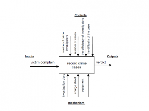
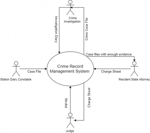
UML diagrams are used to model CRMS in order to show the system details. The paper illustrates the flow of the crime investigations department of a typical police station in which the system provides an end-to-end process for crime records management. Figure 1 is an IDEFO diagram showing details of the system inputs, outputs, controls, and mechanism. The crime records management process and the verdict are the output of the system. The controls that limit the process activities are the number of crime investigators assigned to cases, the difficulty of the case, the efficiency of investigators, and the number of cases filed. The mechanism is the method and tools used to execute the activities, which are investigating diary, charge sheet, and equipment. In order to clarify the system boundaries and to identify the flow of information between the system and external entities, a context diagram is used as shown in Figure 2. The diagram shows the whole system as a one single process. The Station Diary Constable sends the case file, which is then investigated and documented in the investigation diary by the Crime Investigation Department. After that, the Resident State Attorney presses charge based on the charge sheet. Finally, the verdict is given by the judge in court after receiving the charge sheet from attorney.
Figure 1. IDEF0 Diagram
Figure 2. Context Diagram for CRMS
3.1 Functional modelling
3.1.1 Use case diagram
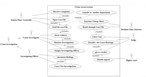
A use case is a methodology used in system analysis to identify, explain, and organize system requirements [14]. A use case helps in visualizing the requirements of the system that will be later used in design and implementation [15]. The use case diagram for CRMS illustrates the interactions between users and crime record system as shown in Figure 3, in which the actors of the system receive a complaint from the user and act accordingly to open a case file by station diary constable. After opening a file case, evidence is checked, and the investigations are monitored by crime investigator. The crime investigator assigns an investigating officer to the opened case. The investigating officer starts to document the findings and carry out investigations.
Resident state attorney sends sanction charge sheet and reads through case file. Finally, the judge presides the court hearings, gives a verdict and close the case and higher court handles appeals, if any. There are relationships which are used in the use case diagram and are represented by using <<extend>> and <<include>>. For example, an <<extend>> relation occurs when the case is not criminal in nature, the case file is then sent to another department. Another extend relation occurs when there is not enough evidence for the resident state attorney to press charges and when no more investigations are required, the cases are closed. Example of the <<include>> relationships is that receiving a complaint includes opening the case file, and checking evidence includes monitoring investigations. Table 1 depicts a definition of all the use cases and the associated actors while Table 2 defines all actors connected to the system.
Figure 3. Use case diagram
Table 1. Use case glossary
|
Use Case Name |
Use Case Description |
Actors (Roles) |
|
Send Case File |
The use case describes the event of sending the complaint file to the investigation department to collect evidence for the case |
Station Diary Constable |
|
Monitor Investigation |
This use case describes the event of investigating crime evidence and monitoring the investigations to gather all essential evidence |
Crime Investigator |
|
Carry out investigations |
This use case describes the event of carrying out investigations while documenting findings in the Diary of Investigations |
Investigating officer |
|
Sanction Charge Sheet |
This use case describes the event of reading through case files and checking evidence to sanction charge sheets. |
Resident State Attorney . |
|
Close Case |
This use case describes the event of giving a verdict and closing a case by the Judge. |
Judge |
Table 2. Actors glossary
|
Actor |
Synonym |
Description |
|
Station Diary Constable |
|
Responsible for receiving complaints, extracting information from victims, and sending case files to correlated departments. |
|
Crime Investigator |
OC/CID |
Responsible for assigning investigating officers, monitoring them, and validating evidence. |
|
Investigating officer |
|
Responsible for carrying out investigations and documenting findings in the Investigation Diary. |
|
Resident State Attorney |
Prosecutor |
Responsible for reading through case files and checking evidence to press charges and sanctioning charge sheet. |
|
Judge |
|
Responsible for presiding over court hearings and giving verdict. |
3.1.2 Activity diagram
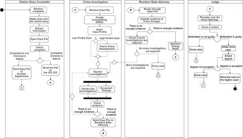
The activity diagram portrays the sequence of activities from a start point to a finish point showing the various decision paths that exist while the activity is being executed. In the crime record system, the activity diagram is divided into four lanes: the station diary constable, the crime investigation, resident state attorney, and judge. (Figure 4).
The system is initiated by the victim filing a complaint at the counter in the police station. The station diary constable receives the complaint and extracts the information required to open the case file. However, the constable checks first the incident type to check if the complaint is not criminal in nature, for example, vehicle accident. In case the incident is non-criminal, it is sent to another department. On the other hand, a criminal incident is transferred to the crime investigation department.
The crime investigation department accepts the file case and assigns a crime investigator to the case. Primarily, the case profile is checked if it is a high-profile case in order to inform the police headquarters, hence the crime investigator begins the inspection of the crime. At the same time, investigations’ findings and evidence are documented by the investigating officer. In order to send the case file to resident state attorney, the inspector checks if the evidence is enough, otherwise the investigation continues until evidence is validated and is found enough for the case. The resident state attorney obtains the case file to read through it and validate evidence to press chargers. Nonetheless, the evidence is checked in order to identify if the case requires more investigation. On the other hand, resident state attorney sanctions the charge sheet and transfers it to the judge. In the adjudication stage, the judge presides over the court hearings and then gives a verdict. The defendant can appeal judge verdict for the higher court to check, otherwise, the crime case is closed.
3.1.3 Structural models
Class Diagram. A class diagram defines a static representation to a system in which it shows the collaboration among classes and their attributes and operations.
Figure 5 illustrates a class diagram of the CRMS. In the class diagram, Stationary Diary Constable Crime Investigator, The Investigating Officer, Resident State Attorney, Judge, and Accuser are inherited from Person class with a generalization relationship. The Victim, Station Diary constable, Accuser classes are associated by aggregation relationship. The Crime Case File class is associated with various classes such as the Complaint, Investigation Diary and Accuser. For example, The Complaint class IsPartOf Crime Case File class with a many-to-one relationship, in which Crime Case File class can have more than one complaint to the same accuser. Moreover, Investigation Diary IsPartOf Crime Case File class with a one-to-one relationship because each crime case will have only one date. In addition, the Crime Investigator class DocumentIn in the Charge Sheet class the findings, his/her name and signature and charge ID, and these classes share a many-to-many relationship. Furthermore, a Charge Sheet class is Applied to the Accuser Class with many-to-one relationship (and vice versa), in which more than one accuser can have more than one charge sheet.
3.2 Behavioral models
3.2.1 Sequence Diagram
The sequence diagram illustrates the objects that participate in a use case and sequence of messages that pass between them over time for one use case [16]. The sequence diagram in Figure 6, is Send Case File. The diagram illustrates the sequence when the victim goes to the police station and files a complaint. The Station Diary Constable receives the complaint, extracts information of the victim, and makes entry into station diary, then, opens a case file and checks the nature of the complaint. If the complaint is criminal in nature, the crime case file is sent to the Crime Investigator. If the case is not criminal in nature, the Station Diary Constable sends the case file to another department.
The sequence diagram in Figure 7, represents the sequence of checking evidence. It starts with the Station Diary Constable who sends the crime case file to the Crime Investigator. The Crime Investigator assigns an Investigating Officer who checks the case profile. If the case is high profile, the Crime Investigator informs the police headquarters. However, if the case is low profile, the Crime Investigator monitors investigations. In addition, the Crime Investigator checks the evidence and sends them to the assigned Investigating Officer to carry out investigations and document the findings in the Investigating Diary. Finally, the Crime Investigator checks if the evidence is enough, he sends the crime case file to the Resident State Attorney. If evidence is not enough, the Crime Investigator continues monitoring investigations.
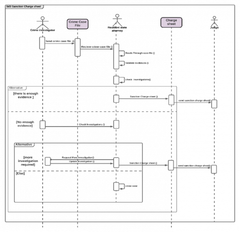
The sequence diagram in Figure 8 shows the interactions between Crime Investigator, Resident State Attorney and the Judge. The process starts with the Crime Investigator sending the Crime Case File class to the Resident State Attorney to read them. The Resident State Attorney then validates evidence. If there is enough evidence, the Resident State Attorney sanction charge sheet, which is a class, to the Judge. If there is not enough evidence, the Resident State Attorney checks investigations. There is another alternative for checking investigations. The Resident State Attorney may request more investigations if they are required, and the Crime Investigator sends a message with the updates, sanctions charge sheet, and sends it to the judge. If there is not enough evidence and no more investigations required, then the Resident State Attorney closes the case.
Figure 6. Sequence diagram of send case file
Figure 7. Sequence diagram for check evidence
Figure 8. Sequence diagram for sanction charge sheet
Figure 9. Sequence diagram for give verdict
The sequence diagram in Figure 9 shows the sequence of giving a verdict. It starts with the Charge Sheet being sent by the Resident State Attorney and received by the Judge. The Judge’s responsibility is to preside and oversee the court hearings then give verdict of the Accuser either guilty or not. If the Accuser is proven innocent, then the case is closed. If the accuser is guilty, the Judge initially closes the case. The Accuser has the right to request an Appeal. The Appeal is then checked by the Judge to see if it is accepted or not. If accepted, then the Judge sends the case to Higher Court, if rejected, then the case is closed.
3.2.2 Communication diagram
A communication diagram shows how objects interact with each other to achieve a behavioral goal [17]. The difference between communication diagram and sequence diagram is that the communication shows the structural relationships among objects. The numbers on the messages show the sequence of sending those messages, and arrows show the direction of flow. Figure 10 is a communication diagram of checking evidence. The path starts with the Station Diary Constable interacting with Crime Case File class by sending a message with the crime case file. The class then interacts with Crime Investigator, who self-delegates many messages which are 4, 4:1, 4:2 and 7:2, upon receiving the crime file. The Crime Investigator has interactions with both the Investigating Officer and the Resident State Attorney. The interaction between Crime Investigator and Investigating Officer is by sending messages about assigning Investigating Officer and checking evidence. Then Message 7:1 (sending case file) is sent by the Crime Investigator to the attorney after checking evidence. The Investigating Officer interacts with itself and with the Investigation Diary class by carrying out investigations and documenting findings in the Investigation Diary.
3.2.3 State-Machine diagram
State machine diagrams represent the behavior of an object. There are different states of an object within the system.
The state machine diagram in Figure 11, illustrates the state of the Crime Case File, which is the main object that has various states in the system. The state machine diagram is initiated by opening a case file. After that, “check case profile” state is triggered when the case file is sent to the crime investigator. If the case is high profile, the crime investigator informs police headquarter. Otherwise, when the case is low profile, the crime investigator starts the investigating process. During the investigation, the evidence is documented in the crime case file. The following state of the Crime Case File is “Reading Case File” by the resident state attorney.
The next state is validating case evidence, which triggers a decision of requesting more investigation or the evidence is enough, then, sanction charge sheet of the case. Hence, the “Case Court Hearing” state is triggered by sending the case file to the judge, which results in deciding the verdict. If the verdict is not guilty, the state of the crime case file is terminated. However, if the verdict is guilty, the case is initially closed. The “Check Case Appeal” is triggered when the accuser files an appeal. If the appeal is not accepted by the judge, the case would be finally closed. Otherwise, the case would be sent to the higher court to give the final verdict and close the case. A decision that is determined by crime investigator is whether to send the case file to the resident state attorney, or not, and that depends on whether there is enough evidence or not. If the evidence is not enough, the crime investigator shall continue investigations.
UML is a standardized modeling language consisting of an integrated set of diagrams, developed to help system and software developers for specifying, visualizing, constructing, and documenting the items of systems, as well as for business modeling. This paper used UML diagrams to represent the Crime Record Management system, by visualizing processes and interactions among actors of the system for the four stages. UML modeling provided a thorough, detailed, and clear picture of the system. This perspective is considered both, a clear visualization and documentation tool to guarantee accurate system operation and serves as a starting point to implement a software system, by providing a good understanding and representation of all the system details, information, and flows. The future of this system is to be implemented through case study to view the system capabilities and several details and aspects that could be added to it. As a result, this would facilitate in identifying the system’s limitations, which in return would assist in enhancing and updating the system to be more accurate and reliable.
[1] Tomas, G.J., Chen, J.S., Cruz, R.D., Pelacio, J.G. (2019). Development of an online crime management & reporting system. The Scientific World Journal, 131: 164-180.
[2] Grady, J.O. (2006). System Requirements Analysis. Elsevier Academic Press.
[3] Meryem, E., Nafil, K., Touahni, R. (2018). Automatic transformation of user stories into UML use case diagrams using NLP Techniques. Procedia Computer Science, 130: 42-49. https://doi.org/10.1016/j.procs.2018.04.010
[4] Rajagopal, D., Thilakavalli, K. (2017). A study: UML for OOA and OOD. International Journal of Knowledge Content Development & Technology, 7(2): 5-20. https://doi.org/10.5865/IJKCT.2017.7.2.005
[5] The British Council. (2015). Crime Management System.
[6] Awodele, O., Olufunmike, O. (2015). A real-time crime records management system for national security agencies. European Journal of Computer Science and Information Technology, 3(2): 1-12.
[7] Nawaz, S., Ghaffar, J., Siddique, A., Aslam, M. (2019). On-line crime records management system: A case of Pakistan. Information Engineering and Applications, 9(6): 11-20. https://doi.org/10.7176/JIEA/9-6-02
[8] Tabassum, K., Shaiba, H., Shamrani, S., Otaibi, S. (2018). E-Cops: An online crime reporting and management system for Riyadh city. 2018 1st International Conference on Computer Applications & Information Security (ICCAIS), pp. 1-8. https://doi.org/10.1109/cais.2018.8441987
[9] Khan, A., Singh, A., Chauhan, A., Gupta, A. (2019). Crime management system. International Research Journal of Engineering and Technology (IRJET), 6(4): 2115-2118.
[10] Chemere, M., Yibeltal, L., Aziz, Y., Bayih, T. (2010). Web Based Criminal Record System. Doctoral Dissertation Debre Markos University. https://www.scribd.com/document/514332013/Web-Based-Criminal-Recored-System.
[11] Yaser Nasr, S., Kassem, S. (2020). Modeling the production planning and control system using UML. 2020 2nd Novel Intelligent and Leading Emerging Sciences Conference (NILES), pp. 21-26. https://doi.org/10.1109/niles50944.2020.9257906
[12] Mohammed, A.R., Kassem, S.S. (2020). UML modeling of online public bus reservation system in Egypt. 2020 International Conference on Data Analytics for Business and Industry: Way Towards a Sustainable Economy (ICDABI), pp. 1-6. https://doi.org/10.1109/icdabi51230.2020.9325604
[13] Abdullatif, N., Kassem, S. (2020). Modelling of agent-based vehicle routing problem using unified modelling language. Journal Européen Des Systèmes Automatisés, 53(6): 781-789. https://doi.org/10.18280/jesa.530604
[14] Dobing, B., Parsons, J. (2003). The role of use cases in the UML: a review and research agenda. Advanced Topics in Database Research, 1: 367-382. https://doi.org/10.4018/978-1-930708-41-9.ch019
[15] Sengupta, S., Bhattacharya, S. (2006). Formalization of UML use case Diagram-a Z notation based approach. 2006 International Conference on Computing & Informatics, pp. 1-6. https://doi.org/10.1109/icoci.2006.5276507
[16] Dennis, A., Wixom, B.H., Tegarden, D. (2012). System Analysis Design UML Version 2.0: An Object-Oriented Approach. Wiley; 2nd edition.
[17] Samuel, P., Mall, R., Kanth, P. (2007). Automatic test case generation from UML Communication diagrams. Information and Software Technology, 49(2): 158-171. https://doi.org/10.1016/j.infsof.2006.04.001