Riad Saidi* | Nada Cherrid | Tarek Bentahar | Hicham Mayache | Atef Bentahar
© 2020 IIETA. This article is published by IIETA and is licensed under the CC BY 4.0 license (http://creativecommons.org/licenses/by/4.0/).
OPEN ACCESS
The transmission of images from satellites to earth is on the brink of many threats which can affect the confidentiality of the data as well as its quality. Several encryption algorithms are used to secure the transmitted images. The objective in this work is to analyze the sensitivity of a particular type of satellite image, which is an interferogram from interferometric imaging systems inSAR system. This image is encrypted by cryptosystem based on the Advanced Encryption Standard with key length of 256 bits (AES-256) standard and the asymmetric Rivest, Shamir & Adelman (RSA) encryption algorithm using Counter-mode encryption (CTR) mode and Output FeedBack (OFB) mode. The analysis made in this paper is carried out on two types of sensitivity. The first analysis is the sensitivity to change of a pixel in the original interferogram and the second is the sensitivity to the key. Two parameters are used to assess sensitivity: The Number of Pixel Change Rate (NPCR) and the Unified Average Changing Intensity (UACI). The obtained results show that the two modes AES-256-OFB and AES-256-CTR are favorable but cannot be implemented on board a satellite without providing a mechanism capable of compensating for the low resistance to error propagation. Metrics on the clear and encrypted interferogram are exploited such as the Structural Similarity Index (SSIM), Gradient-based Structural Similarity (GSSIM), The use of these metrics, allowed us to see that a change of one pixel in the interferogram and the change of the encryption key will affect the quality of the interferogram, as well as a statistical histogram analysis.
AES-256, inSAR crypt interferogram, RSA, UACI, NPCR, SSIM, GSSIM, encryption mode CTR, encryption mode OFB
Thanks to observation instruments installed on satellites, we can have so-called satellite images. Several fields exploit these images such as meteorology, agriculture, forestry, urban traffic, military, and other fields. They have become an obligatory means [1]. Due to their importance, they must be secured against unauthorized access (confidentiality), protected against unauthorized changes (integrity), and available to an authorized entity when necessary (Authentication) [2].
The research work of this article falls within the framework of the security of satellite images, in particular the interferograms resulting from an inSAR system. The originality of our work consists in the analysis of the sensitivity of an interferogram originating from an inSAR system encrypted by a cryptosystem based on two algorithms AES and RSA with two encryption modes OFB and CTR, to pixel change and change of encryption key, using the two parameters NPCR and UACI for the sensitivity test. An inSAR system interferogram is based on the independent scanning of light, therefore it illuminates the surface with its own source of electromagnetic waves [3]. This type of image is exploited in several fields such as: Earth observation, meteorology, and cartography [4, 5]. Two images are provided by an inSAR system: One amplitude image and the other phase. The two inSAR images are produced from the complex correlated signal using two acquisition antennas. The image of the inSAR phase, known as an interferogram, is naturally enveloped in [-π, + π], to recover the true phase value, an unwinding process must be carried out. This process consists in finding the cycle number which will be added to each pixel [6].
Several techniques exist for securing satellite images, we mention among them the symmetric public algorithm AES (Advanced Encryption Standard), it has been approved as an encryption standard by National Institute of Standards and Technology (NIST) is chosen by several organizations around the world. The AES algorithm is a symmetric block cipher process in which the transmitter and receiver use a single key for encryption and decryption. It processes 128-bit (16 bytes) data blocks using 128, 192, or 256-bit encryption keys [7]. As part of a practical implementation, the AES algorithm is combined with a series of simple operations to improve security without compromising the efficiency of the algorithm. This combination is called a cryptographic mode, such as the mode OFB-Output FeedBack, and the mode CTR-Counter-mode Encryption, used in this article. These modes are methods for using block ciphers, we speak of operating modes [8].
The Consultative Committee for Space Data Systems (CCSDS) recommends AES for data encryption in civil space missions. There are other encryption algorithms such as, the asymmetric RSA algorithm (Rivest, Shamir and Adleman) [9], and the IDEA algorithm (International Data Encryption Algorithm) [10]. Some satellite uses algorithm 3- DES to encrypt images. In our work the cryptosystem for interferogram encryption used is based on AES-256, which is the successor to Date Encryption Standard (DES) [11], for inSAR interferogram encryption. The RSA algorithm is used to ensure secure exchange of keys. The use of encryption technology in spacecraft lags far behind terrestrial systems [12], despite the availability and existence of several encryption algorithms. Knowing that it is difficult to establish a true state of the art on the encryption methods used on board satellites since most manufacturers and owners of satellites do not share this type of information. While, some document cites the encryption algorithms used in some space missions [13]. In image encryption, the two parameters NPCR and UACI [14, 15] are commonly used to analyze and test the encryption resistance to differential attacks. The NPCR and UACI are designed to test the number of changing pixels and the number of average modified intensity between ciphertext images, respectively, when the difference between the plain text images is subtle (usually a single pixel) [16].
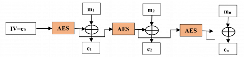
The algorithms used in this work are based on two encryption algorithms, one symmetrical which is AES-256, the other asymmetrical which is the RSA algorithm, which is illustrated in (Figure 1).
Figure 1. Cryptosystem transmission
AES is an algorithm based on a symmetric key block cipher, developed in 1998 by Joan Daemen and Vincent Rijmen. It is designed to process any type of data. The data block length is fixed at 128 bits, while the key can take a length of 128, 192, or 256 bits. The 128-bit length data in AES is divided into four basic operational blocks. The data is a byte array which is organized as a 4 × 4-dimensional matrix which is also called a state matrix and which in turn is subjected to various transformations. For a complete encryption, the number of rounds used is variable N = 10, 12, 14 according to the key length of 128 192, and 256 respectively. Each cycle of this algorithm uses the principle of permutation and substitution. It is suitable for both hardware and software implementation [17]. In our work, the algorithm used has a key length of 256 consequently the number of turns is 14 rounds. For civilian space missions, the Consultative Committee for Space Data Systems (CCSDS) recommends using AES as a symmetric encryption algorithm [18].
For more security and efficiency, the AES algorithm can be combined with a series of simple encryption modes to improve security without penalizing the efficiency of the algorithm itself [19, 20], such as:
Electronic Code Book (ECB)
Cipher Bloc Chaining (CBC).
Cipher FeedBack (CFB).
Output FeedBack (OFB).
Counter-mode encryption (CTR)
The main criteria for choosing between OFB mode and CTR mode for satellite image encryption are [21]:
• Propagation of errors.
• Material complexity.
3.1 AES OFB mode
In this mode, an initial vector is initially encrypted to start the process. The key flow at the output of this block will be reinjected at input to calculate the next key flow (refer to Figure 2).
Figure 2. OFB block cipher mode
Using this mode, the preprocessing of the key flow is possible because it does not depend on a clear message. This mode is useful in satellites for which minimizing the number of on-board circuits is crucial [22].
3.2 AES CTR mode
CTR mode is simple, it creates a stream of pseudo-random numbers independent of the plain text. Figure 3 shows Counter-mode encryption (CTR). In this mode, the key flow is obtained by encrypting successive values of a counter which is then XORE with the message in plain text to generate the encrypted message [23, 24]:
Figure 3. CTR block cipher mode
Counter values used with an encryption key must be nonces, because the key flow should never be repeated. because the key flow should never be repeated. In this mode, and unlike other mode, there is no feedback or sequential processing of the blocks. Therefore, it is possible to perform several ciphers in parallel which is a significant advantage in high performance applications [24]. This mode is recommended by the CCSDS for the encryption of telemetry (TM) and remote control (TC) [25].
The RSA algorithm was created in 1977, named after its creators Rivest, Shamir & Adelman. It is an asymmetric public key encryption algorithm. It uses two keys: public key for encryption and private key for decryption. The RSA algorithm consists of three steps. The first is key generation which is to be used as a key to encrypt and decrypt data. The second step is encryption, where the actual process of converting plain text to cipher text is in progress. The third step is decryption, where the encrypted text is converted to plain text on the other side. The size of the key is from 1024 to 4096 bits [9, 26].
The sensitivity analysis of the inSAR cipher interferogram proposed in this article is based on an AES-256 cryptosystem using two encryption modes (OFB, CTR). The image used is an interferogram from the inSAR system. The sensitivity analysis of the interferogram encrypts by the two modes aims to determine the most suitable mode for the encryption of this type of images. Two parameters are used to assess sensitivity: NPCR and UACI. The Structural Similarity Index (SSIM), and Gradient Based Structural Similarity (GSSIM), are used to confirm the influence of pixel change in the original interferogram, and the influence of key change in the cipher interferogram, as well as statistical analysis of original and cipher interferogram histograms, for both encryption modes of AES-256-CTR and AES-256-OFB.
Figure 4. Original interferogram int1
The two modes of the AES-256 are simulated and evaluated on a 2.53 GHz Pentium I-5 PC with Windows 7 and 4 GB of RAM. For the simulation part, Matlab 2016 software is used as well as interferogram encryption algorithms. The image processed is an interferogram from the inSAR system illustrated in the Figure 4, with different information and a geographical region which are indicated in Table 1.
Figure 4 represents a geographical part of the region of Sardinia taken in August 1991. It is a rolled image and after decryption it will undergo a phase unwinding operation, to see the image of the said region.
Table 1. Characteristics of the interferogram being studied
|
|
Imaged region |
Taken on |
|
Interferogram int 1 |
Sardinia |
Aug 2, 1991 |
|
Orbit |
Baseline(m) |
|
|
241 |
126 |
|
|
Residues rate (%) |
||
|
0.0621 |
||
We will present in this part the results of encryption of the interferogram for both OFB, and CTR, as well as the sensitivity analysis performs, with the structural similarity index (SSIM), and the structural similarity index at gradient base (GSSIM) as metrics and original interferogram histograms and figure as statistical analysis.
6.1 Sensitivity analysis
Two types of sensitivity must be analyzed. The first analysis is the sensitivity to the change of a pixel in the original interferogram (in clear). The second is the sensitivity to the key. Two parameters are exploited for this sensitivity analysis: NPCR and UACI.
6.2 Number of Pixel Change Rate (NPCR)
NPCRs are designed to test the number of changing pixels between two encrypted images (our case study images are inSAR interferograms), when the difference between clear (original) images is delicate (generally a pixel) [26, 27]. The optimum NPCR value is 99.61% [28]. The NPCR can be defined mathematically by the Eq. (1) [16]:
$N P C R=\frac{\sum_{i=1}^{M} \sum_{j=1}^{N} D(i, j)}{M * N} 100 \%$
$D(i, j)=\left\{\begin{array}{l}0, \text { if } C 1(i, j)=C 2(i, j) \\ 1, \text { if } C 1(i, j) \neq C 2(i, j)\end{array}\right.$ (1)
where:
M and N are the width and height of the encrypted interferogram.
C1(i,j): is the interferogram encrypted before a pixel change.
C2(i,j): is the encrypted interferogram after a pixel change.
D(i,j): is a bipolar network.
6.3 Unified Average Changing Intensity (UACI)
UACI is designed to test the number of mean intensities modified between two encrypted images (in our case the images are the interferograms), when the difference between the clear (original) images is subtle (generally a pixel) [1]. The optimal UACI value is 33.46% [28].
UACI can be defined mathematically by the Eq. (2) [16, 29]:
$U A C I=\frac{1}{M * N}\left[\frac{\sum_{i=1}^{M} \sum_{j=1}^{N}(C 1(i, j)-C 2(i, j))}{255}\right] 100 \%$ (2)
where:
M and N are the width and height of the encrypted interferogram.
C1(i,j): is the interferogram encrypted before a pixel change.
C2(i,j): is the encrypted interferogram after a pixel change.
6.4 Sensitivity to a pixel change in the original interferogram
An interferogram encryption system should be sensitive to a pixel change in the original interferogram (in plain text). This requirement is the most important to resist differential attacks. This sensitivity means that a small change in the clear interferogram must cause a significant change in the encrypted interferogram [28]. To analyze and test the influence of a pixel change on the encrypted interferogram, we used the Number of Pixel Change Rate (NPCR) and the Unified Average Changing Intensity (UACI). For a pixel change in the original int1 interferogram. The following procedure was applied:
(1). Encrypt the original interferogram (int1) to generate the first encrypted interferogram (C1).
(2). Change a bit in int1 to obtain a second original interferogram (int2). int1 and int2 are the same with a difference of only one bit, this bit is chosen at the beginning, in the middle or at the end of the first block.
(3). Encrypt the original interferogram (int2) to generate the second encrypted interferogram (C2).
(4). Finally, calculate the NPCR and UACI between the two interferograms (C1 and C2).
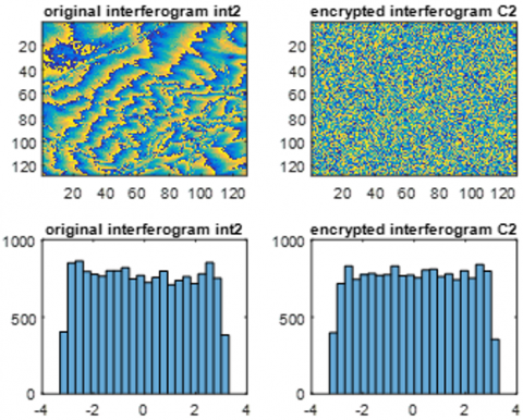
Figures 5 and 6 illustrate the original interferogram int1 and int2 before and after change of pixels respectively, int2 comes from the original interferogram int1 after change of pixels, with the ciphered interferograms C1 of int1 and C2 of int2, as well as their histograms for both modes AES-256-CTR and AES-256-OFB, show us the total dissimilarity between the histograms of C1 and C2, So a change of pixels caused a total dissimilarity.
From Figure 5, we clearly see the difference in histograms of the two interferograms int1 and int2, indicating their differences even with a single pixel.
(a)
(b)
Figure 5. Encrypted interferogram and AES_256-OFB mode histogram, (a) interferogram int1, (b) interferogram int2
(a)
(b)
Figure 6. Encrypted interferogram and AES-256-CTR mode histogram, (a) interferogram int1, (b) interferogram int2
Table 2. SSIM between original interferogram int 1 and int2
|
SSIM etween int1 and int2 |
AES-256-OFB |
AES-256-CTR |
|
0.0668 |
0.0669 |
Table 3. GSSIM between original interferogram int 1 and int2
|
GSSIM between int1 and int2 |
AES-256-OFB |
AES-256-CTR |
|
0.1299 |
0.1299 |
Table 4. Sensitivity to the change of a pixel in the original int1 interferogram
|
|
Interferogram int1 |
|
|
AES-256-OFB |
AES-256-CTR |
|
|
NPRC (%) |
0.0061 |
0.0061 |
|
UACI (%) |
0.0014 |
2.1232e-04 |
We used the structural similarity index (SSIM) [29] and the gradient-based structural similarity index (GSSIM) [30], to see the differentiation between int1 and int2, which is not noticed by l naked eye. The values obtained after simulation of the SSIM and of the GSSIM are transcribed in the two Tables 2 and 3 respectively, show us that the original interferogram int1 and the interferogram int2 resulting from int1 after change of pixels, are not identical, therefore a change of a pixel implies a completely different interferogram, which is very important for interferogram securing, which implies that practically the information contained in the two interferograms are different., due to the change of pixels.
As we can see, from Table 4, the values obtained from the two parameters NPCR and UACI by the modes AES-256-CTR and AES-256-OFB are almost zero. This implies that the two modes have a low capacity to resist differential attacks. Therefore, if there will be a change of pixels in the interferogram we want to secure that will bring us back to data loss after the decryption operation.
6.5 Sensitivity to the secret key
(a)
(b)
Figure 7. Encrypted interferogram int1 and histogram, (a) interferogram int1 mode AES-256-OFB with key1 and key2, (b) interferogram int1 mode AES-256-CTR with key1 and key2
Key sensitivity is extremely important for any cryptographic system [26]. A cryptographic system has a high level of security in terms of sensitivity to the key if a slight modification of the secret key produces an encrypted image (our case study the images are inSAR interferograms) completely different [31].
The scenario used to quantify the sensitivity to the key is as follows:
(1). Two different secret keys (namely, Key1 and Key2) with single bit, are used.
(2). Encrypt the original interferogram int1 by Key1 to get C1.
(3). Encrypt the original interferogram int1 by Key2 to get C2.
(4). Finally, Eqns. (1) and (2) are used to calculate the NPCR and the UACI.
Figure 7 shows the original int1 interferogram, and its C1 crypt interferogram with key 1 and its C2 crypt interferogram with key 2, as well as their histograms for the two encryption modes AES-256-CTR and AES-256-OFB, where we can clearly see on the histograms of C1 and C2 the influence of changing the encryption key, which caused a total difference.
With the naked eye we also cannot in this part make the difference between the two interferograms encrypted of int1 with two different keys key1 and key2, for this we use the two metrices: the structural similarity index (SSIM) and l Gradient-based structural similarity index (GSSIM) to see the difference.
The two Tables 5 and 6 respectively show the values of the SSIM and of the GSSIM between the interferograms C1 and C2, which shows that the two-digit interferograms C1 with key 1 and C2 with key2, are not identical. Even their histograms show it clearly, which implies that practically the information contained in the two interferograms are different, due to the change of the encryption key.
As can also be seen in the case of the sensitivity to the encryption key, from Table 7. The values obtained after simulation of the NPCR parameter are very close to the optimal values, this clarify that the number of changing pixels in the Interferogram encrypts either with key 1 or key 2 will not affect the interferogram obtained after decryption, while the values of the UACI parameter are low compared to the optimal value. This implies that, if the encryption key undergoes a change, the number of mean intensities is changed between the two crypt interferograms.
Table 5. SSIM between encrypted interferograms C1 and C2
|
SSIM between C1 and C2 |
AES-256-OFB |
AES-256-CTR |
|
0.0054 |
0.6625 |
Table 6. GSSIM between encrypted interferograms C1 and C2
|
GSSIM between C1 and C2 |
AES-256-OFB |
AES-256-CTR |
|
0.6637 |
0.6625 |
Table 7. Sensitivity to the key
|
|
Interferogram int1 |
|
|
AES-256-OFB |
AES-256-CTR |
|
|
NPRC(%)_ |
99.6521 |
99.6460 |
|
UACI(%) |
8.2516 |
8.2353 |
The work presented in this article is based on the analysis of the sensitivity of a particular type of satellite image, which is an interferogram from the inSAR system, encrypted by cryptosystem based on the AES-256 standard and the encryption algorithm asymmetric RSA using Counter-mode encryption (CTR) And Output FeedBack (OFB) mode.
In this article, a first analysis is made on the sensitivity to change of a pixel in the original interferogram and the second is the sensitivity to the key. For this analysis, two parameters are used to assess the sensitivity: the number of pixels of the rate of change (NPCR) and the unified mean intensity of change (UACI), The first analysis gave values of NPCR and UACI by Modes AES-256-CTR and AES-256-OFB which are almost zero. As a result, indicating the poor ability to resist differential attacks, hich brings us back to the loss of information after the decryption operation. For the second analysis. The values obtained for the NPCR parameter are very close to the optimal value for the two modes, which explains that the encryption process is sensitive to the encryption key, while the values of the UACI parameter are low compared to at the optimal value. This implies that, if the encryption key undergoes a change, the number of average intensities will change between the two interferograms encryption. From this we can say that the two modes are favorable, but given the importance of the detection and the correction of errors in the satellites to avoid faulty data transmissions, it is necessary to put a mechanism on board the satellite able to compensate for the low resistance to error propagation. Also remains to say, that OFB mode is most useful in satellites where minimizing the number of on-board circuits is crucial. Regarding the main criteria that can be used to choose between OFB and CTR for satellite imagery encryption is the error propagation and the complexity of the hardware.
Furthermore, we exploited metrics on the original interferogram (in clear) and quantified such as the structural similarity index (SSIM) and the gradient-based structural similarity (GSSIM), which showed that a pixel change, gives a completely different interferogram, which leads to the loss of information, which will threaten the security of the interferograms, the same for the case of a change of encryption key. Statistical analysis of the histograms allowed us to clearly see graphically the difference between the ciphered interferograms resulting from the pixel change in the original interferogram, as well as between the interferograms resulting from the key change cipher.
[1] Bensikaddour, E. (2019). Développement d'un cryptosystème basé sur le standard AES et la théorie du chaos pour le chiffrement des images satellitaires à bord d'un satellite d'observation de la terre. Doctoral thesis in Sciences, Faculty of Electrical Engineering, 30-33. http://hdl.handle.net/123456789/2491
[2] El-Samie, F.E.A., Ahmed, H.E.H., Elashry, I.F., Shahieen, M.H., Faragallah, O.S., El-Rabaie, E.S.M., Alshebeili, S.A. (2013). Image Encryption: A Communication Perspective. CRC Press. http://dx.doi.org/10.1201/b16309
[3] Keith, R. (2014). Radar, Altimeters, Encyclopedia of Remote Sensing. Springer. https://doi.org/10.1007/978-0-387-36699-9_134
[4] Rosen, P.A., Hensley, S., Joughin, I.R., Li, F.K., Madsen, S.N., Rodriguez, E., Goldstein, R.M. (2000). Synthetic aperture radar interferometry. IEEE Proceedings, 88(3): 333-382. https://doi.org/10.1109/5.838084
[5] Baumler, R., Hartl, P. (1998). Synthetic aperture radar interferometry Synthetic aperture radar interferometry. Inverse Problems, 14(4): 1-54. https://doi.org/10.1088/0266-5611/14/4/001
[6] Yu, H.Y, Lan. Y. Yuan, Z. Xu, J. Lee, H. (2019). Phase Unwrapping in InSAR: A review. IEEE Geoscience and Remote Sensing Magazine, 7(1): 40-58. https://doi.org/10.1109/MGRS.2018.2873644
[7] FIPS Publication 197. (2001). Advanced Encryption Standard (AES). National Institute of Standards and Technology, US Department of Commerce. http://csrc.nist.gov/publications/fips/fips197/fips-197.pdf.
[8] Dumont, R. (2009). Cryptographie et Sécurité informatique. Notes de cours. Université de Liège Faculté des Sciences Appliqués, 63-65. https://doc.lagout.org/security/Crypto/2010_cours_crypto.pdf.
[9] Rivest, R., Shamir, A., Adleman, L. (1978). A method for obtaining digital signatures and public-key cryptosystems. Communications of the ACM, 21(2): 120-126. http://dx.doi.org/10.1145/359340.359342
[10] Schneier, B. (1996). Applied Cryptography. John Wiley & Sons, Inc.
[11] Dworkin, M. (2001). Computer security. National Institute of Standards and Technology Special Publication, 800-38F. http://dx.doi.org/10.6028/NIST.SP.800-38F
[12] Robert, Pre. (2008). System DVB MSG. fontana roberto Software, EUMET Cast, 22. https://docplayer.it/storage/23/1785248/1605292827/zB8ZdLA27pqYOSz0EbUOOw/1785248.pdf.
[13] Peng, J., You, M.Y., Yang, Z.M., Jin, S.Z. (2007). Research on a block encryption cipher based on chaotic dynamical system. Third International Conference on Natural Computation, Haikou, China. https://doi.org/10.1109/ICNC.2007.612
[14] Chen, G., Mao, Y., Chui, C. (2004). A symmetric image encryption scheme based on 3D chaotic cat maps. Chaos, Solitons and Fractals, 21(3): 749-761. https://doi.org/10.1016/j.chaos.2003.12.022
[15] Zhu, Z.L., Zhang, W., Wong, K.W., Yu, H. (2010). A chaos-based symmetric image encryption scheme using a bit-level permutation. Information Sciences, 181(6): 1171-1186. https://doi.org/10.1016/j.ins.2010.11.009
[16] Wu, Y., Noonan, JP., Agaian, S. (2011). NPCR and UACI randomness tests for image encryption. Cyber Journals: Multidisciplinary Journals in Science and Technology, Journal of Selected Areas in Telecommunications (JSAT), 31-32.
[17] Sharing Earth Observation Resources. (2018). https://directory.eoportal.org/web/eoportal/satellite-missions.
[18] Pahal, R., Kumar, Vikas. (2013). Efficient implementation of AES. International Journal of Advanced Research in Computer Science and Software Engineering, 3(7).
[19] Abd El-Samie, F.E., Ahmed, H.E.H., Elashry, I.F., Shahieen, M.H., Faragallah, O.S., El-Rabaie, E.S.M., Alshebeili, S.A. (2013). Image Encryption A Communication Perspective. Boca Raton [Florida], CRC Press. https://doi.org/10.1201/b16309
[20] Nigel, P., Smart, Rijmen, V., Gierlichs, B., Paterson, K.G., Stam, M., Warinschi, B., Watson, G. (2014). Algorithms key size and parameters. European Union Agency for Network and Information Security (ENISA). https://doi.org/10.2824/36822
[21] Bensikaddoura, E., Bentoutoua, Y., Talebb, N. (2017). Satellite image encryption method based on AES-CTR algorithm and GEFFE generator. 2017 8th International Conference on Recent Advances in Space Technologies (RAST), Istanbul, Turkey, pp. 247-248. https://doi.org/10.1109/RAST.2017.8002953
[22] Dumas, J.G., Roch, J.L., Tannier, É., Varrette, S. (2007). Théorie des codes: Compression, Cryptage, Correction. Dunod, Paris, 38-41.
[23] Stavroulakis, P., Stamp, M. (2010). Handbook of Information and Communication Security. Springer Science & Business Media. https://doi.org/10.1007/978-1-84882-684-7
[24] Burr, W.E. (2003). Selecting the advanced encryption standard. IEEE Security & Privacy, 1(2): 43-52. https://doi.org/10.1109/MSECP.2003.1193210
[25] CCSDS. 350.9-G-1, (2019). CCSDS Cryptographic Algorithms. Blue Book.
[26] Preethi, M., Nithya, M. (2013). Study and performance of RSA algorithm. International Journal of Computer Science and Mobile Computing, 2(6): 126-139.
[27] Noura, H. (2012). Conception et simulation des générateurs, crypto-systèmes et fonctions de hachage bases chaos performants. Doctoral thesis, École doctorale Sciences et Technologies de l’Information et Mathématiques (STIM), Université de Nantes, France. https://core.ac.uk/download/pdf/52997889.pdf.
[28] Farajallah, M. (2015). Chaos-based crypto and joint crypto-compression systems for images and videos. Doctoral thesis, École doctorale: Sciences et technologies de l’information, et mathématiques universite de nantes, France. https://hal.archives-ouvertes.fr/tel-01179610/document.
[29] Wang, Z., Bovik, A.C., Sheikh, H.R., Simocelli, E.P. (2004). Image quality assessment: From error measurement to structural similarity. IEEE Trans, Image Processing, 13(4): 600- 612. https://doi.org/10.1109/TIP.2003.819861
[30] Guan, H.C., Yang, C.L., Xie, S.L. (2006). Cradient- based structural similarity for image quality assessment. International Conference on Image Processing, IEEE Xplore, Atlanta, GA, USA, pp. 2929-2930. https://doi.org/10.1109/ICIP.2006.313132
[31] Jolfaei, A., Wu, X.W., Muthukkumarasamy, V. (2014). Comments on the security of “Diffusion–substitution based gray image encryption” scheme. Digital Signal Processing, 32: 34-36. https://doi.org/10.1016/j.dsp.2014.05.011