Sunardi*![]() | Moch Agus Choiron
| Moch Agus Choiron![]() | Sugiarto
| Sugiarto![]() | Putu Hadi Setyarini
| Putu Hadi Setyarini![]()
© 2025 The authors. This article is published by IIETA and is licensed under the CC BY 4.0 license (http://creativecommons.org/licenses/by/4.0/).
OPEN ACCESS
This research aims to enhance the crashworthiness of fishing boat hulls, which are susceptible to collisions, by incorporating reinforcements in stiffeners installed transversely and longitudinally, referred to as impact side beams. Simulations with ANSYS and drop tests were conducted to investigate the impact of these side beams on deformation, stress, and energy absorption in the hull's crash area during a collision. The findings demonstrate that installing impact side beams significantly amplifies the fishing boats' hull energy absorption. Furthermore, the transverse installation of impact side beams with a bar profile emerges as the optimal choice, given its lighter additional material requirement and ease of manufacture and installation. This study provides valuable insights into the design of fishing boat hulls, contributing to safer and more efficient maritime operations.
crashworthiness, fishing vessel collision, simulation computer, drop test
Fishing vessel accidents are a significant concern due to the high number of fatalities they cause, emphasizing the need for improved safety measures in the fishing industry. Studies shed light on the patterns and factors influencing these accidents [1, 2] while other research specifically focuses on the operability of traditional small fishing boats in Indonesia, highlighting various operational aspects contributing to accidents [3, 4]. In the realm of ship construction and collision prevention, understanding various factors is crucial [5, 6]. Further research emphasizes the significance of determining the hull girder strength post-damage to assess collision resilience [7, 8]. Analyzing ship collision energy and structural damage across different scenarios provides insights for construction improvements [9, 10]. Additionally, factors like vessel speed and crew number play a role in collision accidents, guiding safety measures and structural enhancements [11, 12].
Preventing ship collisions is paramount for maritime safety [13]. Research focuses on collision damage and energy absorption analysis, while other studies delve into developing collision models for fishing boats and ferry car decks, respectively [14, 15]. These diverse perspectives underscore the multifaceted nature of ship collision prevention, encompassing technological, human, and structural dimensions [16]. This study introduces an innovative approach to installing stiffeners on the sides of ships susceptible to collisions [17]. In maritime applications, integrating such stiffeners on the sides of ships could increase the vessel's resistance to collision forces [18, 19]. This could minimize structural damage and ensure the safety of the crew and cargo. This research aims to explore this concept further, investigating the feasibility and effectiveness of such an approach in improving maritime safety. Future work will involve rigorous testing and analysis to validate the proposed design and assess its impact on overall ship safety. This study contributes to the ongoing efforts in maritime safety research, offering a novel perspective on ship design and collision prevention.
This study employed a combination of simulations using ANSYS and drop test experiments to investigate the design of the side beam impact installation model on the ship's side [20]. The primary objective was to identify a design that maximizes energy absorption, thereby enhancing the safety of fishing vessels during collisions. The ANSYS simulations provided a detailed understanding of the structural behaviour of the side beam impact installation under various collision scenarios [21]. These simulations facilitated the visualization of the design's stress distribution, deformation patterns, and energy absorption characteristics under different impact conditions [22].
Research on structural crashworthiness has been a focal point for many researchers, aiming to enhance the safety of structures under impact loading conditions [23]. Various studies have explored approaches to improve crashworthiness, such as utilizing thin-walled tubular components for energy absorption [24]. Additionally, investigations have been conducted on the crash mechanisms of structures, the impact of uncertainties on crash behaviour, and the optimization of crashworthiness designs for effectiveness and efficiency [25]. Moreover, advancements in crashworthiness applications have led to a shift towards using composite materials in energy-absorbing structures, showcasing their potential for enhancing crashworthiness [26]. Furthermore, specific materials like FRP composites have been studied for improving vehicle crashworthiness by serving as collapsible absorbers of crash energy [27]. Studies have also delved into the crashworthiness of hybrid structures, demonstrating that fibre/metal hybrid materials can offer improved crashworthiness compared to traditional metal structures [28]. Moreover, the crashworthiness of structures like composite hat shapes has been explored for applications in vehicle safety, highlighting their suitability for side-impact crashworthiness [29].
Complementing the ANSYS simulations, drop-test experiments were conducted to validate the simulation results and provide real-world insights into the performance of the side beam impact installation. These experiments involved weighting onto the side beam impact installation and measuring the resulting deformation and energy absorption. The combination of ANSYS simulations and drop test experiments comprehensively evaluated the side beam impact installation design. The findings from this study will contribute to the development of safer and more resilient fishing vessels capable of withstanding collisions and protecting the crew and cargo onboard. This research underscores the importance of innovative design and rigorous testing in enhancing maritime safety.
This study uses finite element analysis and drop test experiments to investigate the effect of adding stiffeners on fishing boat crashworthiness in collision scenarios. ANSYS software simulates fishing boat collisions at 20 and 30 knots with different configurations of stiffeners in the impact area. The Energy Absorption (EA) values of the fishing boat's hull with and without stiffeners under various collision conditions are compared. The finite element method (FEM) simulation of ship collision was performed using ANSYS Research License, which is a software application based on the FEM that can model and analyze various engineering problems [30]. The alloy fishing boat model was created with a length of 15 meters, a width of 4.8 meters, and a height of 2 meters, typical dimensions for small fishing vessels [31, 32].
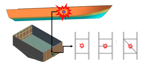
The hull plate was assumed to be made of alloy alloy 5083-H116, which is commonly used for marine applications due to its high strength and corrosion resistance [33]. The material properties of the hull plate and the steel object were taken from the literature [34]. The collision scenarios were set up with two speeds (20 and 30 knots) and angles (0°and 55°) between the boat's longitudinal axis and the impact's direction, as shown in the collision location at the middle of the boat as shown in Figure 1. The stiffener plates were added to the hull plate to increase its stiffness and strength. Two variations of stiffener plates with different shapes (T-shaped and Bar-shaped), as in Figure 2, were tested. The parameters of interest in this analysis were the hull plate's maximum stress, deformation, and energy absorption during the collision. These parameters were used to evaluate the crashworthiness of the alloy fishing boat hulls with the addition of stiffness plates and the existing conditions.
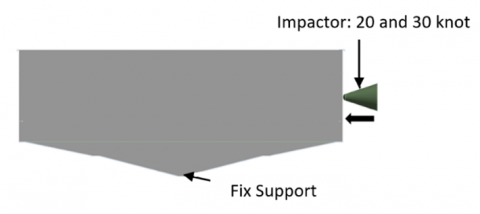
The selected approach for this study is a computer simulation using ANSYS LS-DYNA (see Figure 3). This nonlinear explicit finite element software is capable of modeling material reactions to brief instances of intense stress [35]. The simulated fishing boat's geometry is prepared using CAD software. The next process is material modelling. The mechanical properties and material models used for simulation are summarized in Table 1 [36]. The fishing boat hull (5083-H116 alloy) is modeled using bilinear isotropic hardening with strain-rate sensitivity based on the Cowper–Symonds formulation [37]. The impactor (structural steel) is treated as a rigid-plastic body. Material constants are determined from static and dynamic tests, ensuring accurate representation under impact loading conditions.
Figure 1. The collision of side hull to the sharp object and side beam positions (existing, transverse, and longitudinal)
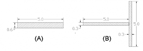
Figure 2. The Profil Bar 6x50 (mm) and T Profil 3x50+50x3 (mm) for side beam impacts shapes
Table 1. The mechanical properties and material models used for simulation
|
Property |
5083-H116 Alloy |
Structural Steel |
|
Density, ρ (kg/m³) |
2770 |
7850 |
|
Elastic Modulus, E (GPa) |
71 |
200 |
|
Poisson's Ratio, ν |
0.33 |
0.3 |
|
Yield Strength, σy |
280 |
450 |
|
Tangent Modulus, Ep (MPa) |
500 |
1450 |
|
Failure Strain, εf |
0.3 |
0.15 |
|
Cowper–Symonds C (s⁻¹) |
6500 |
2850 |
|
Cowper–Symonds P |
4 |
5 |
|
Strain-Rate Sensitivity |
Yes |
Yes |
The bilinear isotropic hardening behavior is described in Eq. (1).
$\sigma(\varepsilon)= \begin{cases}E \varepsilon, \quad\quad\quad\quad\quad\quad\text { for } \varepsilon \leq \varepsilon_y \\ \sigma_y+E_p\left(\varepsilon-\varepsilon_y\right), \text { for } \varepsilon>\varepsilon_y\end{cases}$ (1)
where, $\sigma(\varepsilon)$ is the stress as a function of strain $\varepsilon, \sigma y$ is the yield stress, E and $\mathrm{E}_{\mathrm{p}}$ is the tangent modulus after yielding. With $\sigma y=280 \mathrm{MPa}$ for $5083-\mathrm{H} 116$ alloy and 450 MPa for steel; the yield strain is calculated as $\varepsilon y=\sigma y / E$. The value of Ep (tangent modulus) was obtained from static tensile tests conducted at a low strain rate $(10-3<s<1)$. Strain rate effects using the Cowper-Symonds model, with parameters $\mathrm{C}=6500$ and $\mathrm{P}=$ 4.0, based on experimental data for marine-grade alloys. Dynamic stress amplification follows Cowper–Symonds (Eq. (2)):
$\sigma_d=\sigma_s\left[1+\left(\frac{\dot{\varepsilon}}{C}\right)^{\frac{1}{P}}\right]$ (2)
where, $\sigma_{\mathrm{d}}$ is the dynamic flow stress, $\sigma_{\mathrm{s}}$ is the static flow stress, and $\dot{\varepsilon}$ is the strain rate [38]. The failure strain was set to 0.30 . For the impactor material (structural steel), similar parameters were defined, with $\mathrm{C}=2850$ and $\mathrm{P}=5.0$, treating the impactor as a rigid body [39]. Load modelling uses the crash test method, which is widely used in these industries to model drop and impact simulation to understand product integrity and determine critical regions in the assembly [40].
Figure 3. Setting model in ANSYS analysis
In this modelling, the impactor has a speed of 20 knots and 30 knots with an interval of 0.005 seconds. Its shape is a cone with a ball-shaped tip. The meshing size in the crash box is set with an average skewness value of 5.91×10⁻² [39]. The mesh quality is checked using the aspect ratio and Jacobian criteria [41, 42]. The simulation results are analyzed in terms of stress, strain, deformation, and energy absorption.
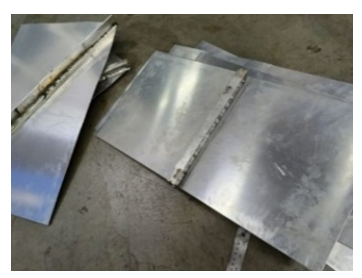
This study conducted drop test experiments using alloy test specimens, which were scaled down to half the actual size of plates with stiffener reinforcement. The primary objective was to assess the crashworthiness of fishing boat hulls, focusing on stiffness changes resulting from side beam impacts. The experimental design incorporated variations in the shapes of stiffeners, including flat bars and T-profiles, along with their respective transverse and longitudinal orientations. To mitigate noise caused by mismatched equipment capacity, high-speed cameras and appropriate filters were recommended [43]. Future tests will use a test rig more closely matched to actual load ranges to improve data reliability. The materials, shapes, and positions of the stiffeners used in the ship’s hull for the drop tests are detailed in Table 2.
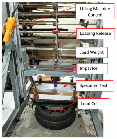
The drop test setup, illustrated in Figure 4, included parameters such as a total load of 39 kg and a drop height of 1.5 meters. The conversion of the load cell voltage readings facilitated the acquisition of force data for each model. The models were constructed at a 1:2 scale relative to the actual dimensions of the ship’s panels. The tested models featured longitudinal spacings of 0.6 meters and truss intervals of 0.3 meters, as depicted in Figure 5. Additionally, a higher-capacity load cell or improved dampening was proposed to reduce signal noise.
The experimental procedure involved subjecting each specimen to an impact generated by a 39 kg impactor hoisted to a height of 1.5 meters using an electric lift. Upon release from its support rope, the impactor descended freely, striking the test material above a load cell. The load cell was tasked with capturing the vibrations induced by the impact load and translating them into an electrical voltage signal. This signal was subsequently interpreted via the LabVIEW application, enabling voltage conversion into the corresponding impact force expressed in Newtons. One limitation of this drop test is the absence of a high-speed camera to investigate the amount of deformation at any given time. Future work will incorporate high-speed video recording to synchronize displacement and force data for more accurate EA analysis.
Figure 4. Specimens model for drop test
Figure 5. Drop test machine
Table 2. Materials, shapes, and positions of the stiffeners employed in the ship’s hull for the drop tests
|
Materials |
Thickness |
Stiffener Profil |
Direction |
Model ID |
|
Mahogany Wood |
40 mm |
- |
- |
Mahogany |
|
Alloy |
5 mm |
No Stif-feners |
- |
Existing |
|
Alloy |
5 mm |
Flat Bar |
Longitudinal |
Long_FB40 |
|
Alloy |
5 mm |
Flat Bar |
Transverse |
Trans_FB40 |
|
Alloy |
5 mm |
T 20x20 |
Longitudinal |
Long_T(20×20) |
|
Alloy |
5 mm |
T 40x20 |
Longitudinal |
Long_T(40×20) |
|
Alloy |
5 mm |
T 20x20 |
Transverse |
Trans_T(20×20) |
|
Alloy |
5 mm |
T 40x20 |
Transverse |
Trans_T(40×20) |
The crashworthiness of alloy fishing boats has been a focal point in research, particularly concerning hull performance and structural integrity during collision scenarios. Computational methods, such as finite element analysis, have significantly contributed to understanding ship hull performance under various conditions, leading to safer and more efficient ship designs [19, 44]. The utilization of computational simulations, especially with ANSYS LS-Dyna, has provided valuable insights into the crashworthiness of alloy fishing boats, offering a deeper understanding of maximum deformation in the crash area and enabling comparative analyses of different collision scenarios [45]
Recent studies have highlighted the effectiveness of incorporating stiffeners, such as longitudinals and brackets, in the hull design of alloy fishing boats to enhance structural integrity under diverse loading conditions. This aligns with findings emphasizing the importance of stiffeners in improving the crashworthiness of these boats. Moreover, the incorporation of stiffeners has been shown to enhance the ultimate compressive strength of panels, with different types of stiffeners like T-bar, flat-bar, and angle-bar being commonly used in shipbuilding. Using stiffeners, in conjunction with advanced computational tools, has proven crucial in optimizing alloy fishing boats' crashworthiness and structural performance under varying conditions. In conclusion, integrating stiffeners and advanced computational simulations, particularly with ANSYS LS-Dyna, plays a vital role in enhancing the crashworthiness of alloy fishing boats by improving hull performance and structural integrity under collision scenarios. These approaches offer valuable insights into deformation patterns, comparative analyses, and the safety of alloy fishing boats, contributing to developing more robust and efficient ship designs.
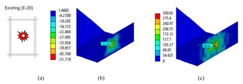
Figure 6. E-20 stiffener ID: (a) Crash area, (b) deformation in mm, (c) stress in MPa
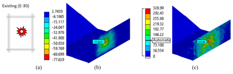
Figure 7. E-30 stiffener ID: (a) Crash area, (b) deformation in mm, (c) stress in MPa
Figure 8. B-20 stiffener ID: (a) Crash area, (b) deformation in mm, (c) stress in MPa
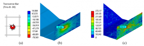
Figure 9. Trns-B-30 stiffener ID: (a) Crash area, (b) deformation in mm, (c) stress in MPa
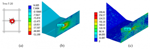
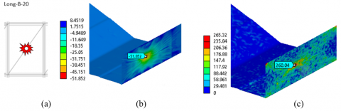
Figure 10. Trns-T-20 stiffener ID: (a) Crash area, (b) deformation in mm, (c) stress in MPa
Figure 11. Long-B-20 stiffener ID: (a) Crash area, (b) deformation in mm, (c) stress in MPa
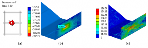
Figure 12. Trns-T-30 stiffener ID: (a) Crash area, (b) deformation in mm, (c) stress in Mpa
Figure 13. Long-B-30 stiffener ID: (a) Crash area, (b) deformation in mm, (c) stress in MPa
Table 3. Values of deformation, stress, reaction force and energy absorption in collision with alloy fishing vessel for simulation with ANSYS
|
Position Side Beam |
Profile Type |
Speed |
Stiffener ID |
Deformation Max (mm) |
Stress Max (Mpa) |
Energy Absorption (kJ) |
|
Existing |
20 |
E-20 |
51.441 |
309.82 |
250.75 |
|
|
Existing |
30 |
E-30 |
77.161 |
328.99 |
779.15 |
|
|
Longitudinal |
Bar |
20 |
Long-B-20 |
51.443 |
288.42 |
1018.37 |
|
Longitudinal |
Bar |
30 |
Long-B-30 |
77.161 |
277.81 |
1609.96 3) |
|
Longitudinal |
T |
20 |
Long-T-20 |
51.443 |
286.01 |
916.14 |
|
Longitudinal |
T |
30 |
Long-T-30 |
77.164 |
278.63 |
1654.94 1) |
|
Transversal |
Bar |
20 |
Trns-B-20 |
51.442 |
277.56 |
1051.84 |
|
Transversal |
Bar |
30 |
Trns-B-30 |
77.166 |
265.32 |
1590.81 |
|
Transversal |
T |
20 |
Trns-T-20 |
51.443 |
272.17 |
979.66 |
|
Transversal |
T |
30 |
Trns-T-30 |
77.161 |
279.29 |
1643.30 2) |
The presented study used computer simulations to analyze the deformation and stress magnitudes in various ship hull impact models. The results of these simulations are comprehensively illustrated in Figures 6-13. Several models were compared, including a ship hull model without side beam impact reinforcement (Figures 6 and 7) and an alloy fishing boat hull model reinforced transversely and longitudinally. The reinforced model was further examined under two distinct conditions, with impact speeds of 20 and 30 knots, respectively. This multi-faceted approach allowed for a thorough investigation of the influence of speed on the structural resilience of the reinforced ship hull. Insights gained from this study are expected to significantly contribute to ongoing discussions on ship hull design and safety, thereby paving the way for future research and practical applications.
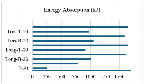
The simulation outcomes, obtained through the utilization of ANSYS, encompass a range of side beams impact variations. These results, which include the degree of deformation, maximum stress, and energy absorption, are comprehensively presented in Table 3 and Figure 14. EA is defined as the total energy absorbed, calculated as the integral of force over deformation. This data provides a robust understanding of the performance characteristics under different reinforcement conditions.
Figure 14. Energy absorption for variation of side beams impact
An investigation has established a direct correlation between collision speed and the ensuing deformation of a ship’s hull. Notably, a collision speed of 20 knots resulted in a deformation of approximately 51.5 mm, which escalated to an estimated 77 mm at 30 knots. While alterations in profile and angle of impact on the side beam had a lesser effect on deformation magnitude, they significantly influenced EA. This is particularly evident when comparing transverse vs. longitudinal installations, where reinforcement orientation alters load distribution and resulting energy dissipation. These distinctions reflect the theoretical EA model and validate simulation observations with experimental trends.
The study's objective was to evaluate the impact of various types of additional stiffeners on the EA of ship structures under impact loads. EA, the area under the reaction force curve versus deformation, represents the energy the ship structure can absorb before failure [46, 47]. Various ship structures with different configurations of additional stiffeners were analyzed using ANSYS software. The impact speed ranged from 20 to 30 knots, and the EA value was computed for each case. The results confirmed that EA increased with impact speed across all cases. Notably, a key finding is that the transverse installation of bar profiles achieves superior EA at 20 knots, whereas the longitudinal T profile yields the highest EA at 30 knots. This demonstrates a performance–speed synergy between profile type and installation direction, offering a practical optimization strategy [48, 49]. However, the current study was conducted on a scaled-down (1:2) model of the fishing boat hull, which limits the direct applicability to full-scale vessels. The generalizability of these findings to real-world, full-scale applications can be inferred, but further validation with actual-sized hulls is necessary. Furthermore, while 5083-H116 alloy proved optimal in this study, alternative materials (e.g., composites, hybrid alloys) could offer different energy absorption and durability characteristics, warranting future testing.
At a collision speed of 30 knots, the configurations that yielded the highest EA were Long_T-30, Trans_T-30, Long_B-30, and Trans_B-30. At an impact speed of 20 knots, the configurations were Trans_B-20, Long_B-20, Trans_T-20, and Long-T-20. These results suggest that at a collision speed of 30 knots, the optimal configuration is the longitudinal installation of a T profile. Conversely, at an impact speed of 20 knots, the transverse installation of a bar profile yields superior EA performance compared to other models. Additionally, environmental factors, such as wave motion and corrosion, were not considered in the current study but could affect beam performance over time, especially in real-world marine environments. Corrosion, in particular, might degrade material properties and reduce the long-term effectiveness of the impact side beams. Future studies should address these environmental factors, using full-scale models and long-term testing under simulated marine conditions [50].
Drop test experiments for structures have been extensively studied in the literature. Conducted experimental observations of an 8 m/s drop test of a metallic helicopter underfloor structure onto a hard surface, focusing on crashworthiness and structural engineering [51]. Investigated free-fall drop impact tests using various sensors and established a relationship between strain and impact energy correlated with drop height [52]. Performed an experimental and numerical crashworthiness study on a full-scale composite fuselage section, emphasizing aerospace applications [53]. Developed a new drop-weight impact machine for studying fracture processes in structural concrete, focusing on materials science and dynamic testing [54]. These studies provide valuable insights into methodologies, results, and implications of drop test experiments in structural engineering and materials science.
A drop test was conducted involving a pointed impactor with a mass of 37 kg being dropped from a height of 1.5 meters. The materials tested were Alloy 1101 and mahogany wood, both with a thickness of 4 mm. The experiment was performed at a 1:2 scale. The data obtained from this experiment was plotted in a graph (Figure 15). The graph exhibits an irregular line at the bottom, attributable to significant noise. This noise results from utilizing a drop test capacity of up to 5 tons for testing a load of less than 100 kg. This noise affected the clarity of the results due to the mismatch between the test capacity and the actual load applied [55]. The study by Ratner et al. [56] provided insights into improving the precision of dynamic mechanical properties determined from drop tower impact testing. The research suggests using a diaphragm to minimize transient shock loads, specialized impact absorbers to reduce noise, and high-speed cameras to observe displacement accurately. These measures can help mitigate the impact of noise on test results and enhance the reliability of data obtained from drop tests.
Figure 15. Noise on drop test experiment
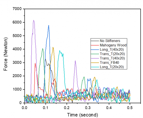
The comprehensive results of the drop test experiment, aimed at demonstrating the crashworthiness of wooden and alloy fishing boat materials both with and without side beam impact reinforcement, are depicted in Figure 16. The graph reveals that the larger the cross-sectional area of the stiffeners, the greater the reaction force of the ship's hull structure can withstand. A larger cross-sectional area results in a larger cross-sectional modulus and a more significant moment of inertia of the stiffener. The cross-sectional area of the stiffeners increases, and the ship's hull structure can withstand greater forces. This relationship is attributed to the larger cross-sectional modulus and increased moment of inertia of the stiffener [57, 58]. The order of magnitude of Force for stiffener ID is as follows: Trans_T(40×20), Long_T(20×20), Trans_T(20×20), Trans_FB40, Long_T(20×20), Long_FB40, Alloy without stiffeners (existing), and Mahogany wood 40 mm. The maximum Force is illustrated in Figure 16 and Table 4. This study provides valuable insights into the structural integrity of fishing boats under various conditions.
Figure 16. Reaction force for all the specimen on drop test experiment
Table 4. The maximum reaction force on drop test experiments
|
Model ID |
Max Force (N) |
|
Mahogany Wood 40 mm |
2956.91 |
|
Alloy (no stiffness) |
3305.70 |
|
Long_T(20x20) |
3906.76 |
|
Trans_T(20x20) |
4049.50 |
|
Trans_FB40 |
4147.10 |
|
Long_T(40x20) |
5785.00 |
|
Trans_T(40x20) |
6160.65 |
The incorporation of side beam impact significantly enhances the structural robustness of the ship’s hull, surpassing the performance of hulls constructed from wood or alloy without side beam impact. In particular, the maximum impact load that a ship’s hull with side beams can endure reaches 6161 Newtons for a transverse impact side beam design with a T cross section (40×20×5) and 5785 Newtons for a longitudinal impact side beam design with an identical T cross-section. By contrast, the maximum impact load for alloy and mahogany materials is 3306 Newtons and 2957 Newtons, respectively [59]. Consequently, the increase in load capacity that can be withstood is nearly 100%. A comparison of maximum force values for all drop test models is depicted in Figure 13 and Table 4.
A comparative analysis of the drop test results for wooden materials, representative of traditional fishing boat materials, and ship hulls with and without 40 mm flat bar side beam impact reinforcement is illustrated in Figure 17. The experimental results reveal distinct behaviours for each material during the drop test. In the mahogany wood case, there was only one peak in the force-time graph, indicating the absence of a second bounce from the impactor on the test specimen. The distance between the maximum force peaks ranged from 0.05 to 0.144, with the maximum force height in the first and second collisions being 2956.91 N and 1831.18 N, respectively. This suggests that the duration of the first collision and the subsequent second collision assisted by the impactor is 0.094 seconds. The maximum force in the first collision is greater than the second, with a difference of 1125.74 N. For the fishing boat hull without side beam impact reinforcement, the short distance between the peaks suggests that the second bounce transpires within a brief time frame, and the height of the impactor bounce is also short, indicative of a low reaction force of the test material. However, in a collision, the maximum force was 3305.70 N, and no second collision was observed, which explains that the plate was immediately deformed far downwards. There was no bounce from the impactor for the second collision to transpire.
Figure 17. Temporal discrepancy between the first and second collisions
Figure 18. Reaction force value based on the direction of side beams impact
In contrast, test specimens with 40 mm flat bar reinforced side beams exhibited the highest reaction force value, with the distance between maximum force peaks being longer, indicative of a more robust structure, which caused the impactor to bounce higher and subsequently a second impact. The maximum force value was 4147.10 N, and the time interval between the first and second collisions was 0.198 seconds, indicating a significant difference compared to the mahogany wood and the alloy ship hull without reinforcement [60]. In sequence, the most significant maximum force is the Alloy hull with flat bar reinforcement of 40 mm, followed by the Alloy hull without reinforcement and the mahogany wood ship material with a thickness of 40 mm.
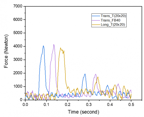
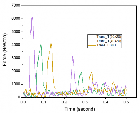
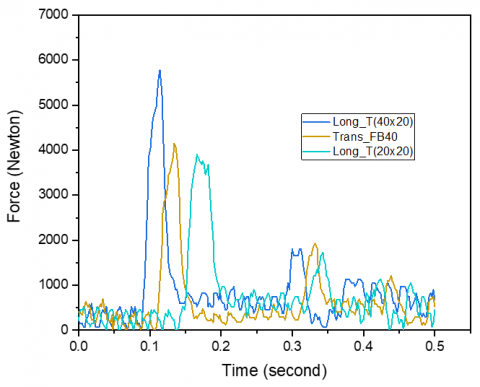
Figures 18-21 present a comparative study of the orientation of Impact Side Beams in mitigating collision loads in ship hull construction. A marginal variation is noticeable between Trans_T(40×20) and Long_T(40×20) designs, with peak impact load values oscillating between 5785 and 6161 Newtons, as depicted in Figure 18. Conversely, the impact of variations in profile shape with an identical cross-sectional area between the Trans_T(20×20) profiles and Trans_FB(20×20) or Long_T(20×20) is also examined. The performance of Trans_FB(20×20) demonstrates marginally higher reaction force values in comparison to the Trans_T(20×20) or Long_T(20×20) models, as illustrated in Figure 19 and Table 4.
Figure 19. Reaction force value based on the stiffener shape designs
Figure 20. Reaction force value based on the difference in sectional area and the shape design of the stiffener
Considering different cross-sectional areas, the Trans_T(40×20) and Trans_T(20×20) models exhibit a discrepancy in the maximum force endured, precisely 5785.00 Newtons and 4049.50 Newtons, respectively. Consequently, the T(40×20) cross-sectional profile yields a marginally superior reaction force compared to T(20×20). Conversely, for an identical cross-sectional area between Trans_FB40 and Trans_T(20×20), where FB 40 denotes reinforcement with flat bars of 40mm height, the maximum stress value that can be sustained is 3907 Newtons. This value surpasses the Trans_T(20×20) and Long_T(20×20) models, which possess the same sectional area. This is illustrated in Figures 19, 20, and 21.
Figure 21. Reaction force value based on the difference in sectional area, direction installation, and shape design of the stiffener
Significant findings have emerged from the drop test experiment. The drop test, conducted at a free fall speed of up to 5.42 meters per second, could generate tangible differences in maximum force across various ship hull reinforcement models (side beams impact). The optimal sequence for reinforcing the ship's hull, based on the maximum force value that the ship's hull model can withstand, is as follows: Long_T(40×20), Trans_FB40, Trans_T(20×20), Long_T(20×20), Alloy (without stiffness), and Mahogany Wood model with a thickness of 40mm. The experimental tests conducted in this research have yet to yield precise values that align with and can be compared to the deformation and stress magnitudes obtained from computer simulation tests (ANSYS). However, the experimental tests replicated the same phenomena and corroborated the simulation results obtained with ANSYS for several simulation test results.
Installing impact side beams, achieved by adding reinforcing profiles to the ship's hull, can augment the structure's reaction force by nearly 100%. This result was derived from comparing the maximum force without side beam impact (3305.70 N) with the installation of a longitudinal T profile (40×20) with the value of maximum reaction force 6160.65 Newton. A larger cross-sectional area of the profile, for instance, T(40×20) compared to T(20×20), produces a higher force resistance and greater EA. Moreover, transverse installations showed superior performance at lower speeds (under 20 knots) transverse layout and material lightweighting allows enhanced performance with reduced structural mass. This insight supports practical implementation in small fishing vessels requiring both safety and material efficiency.
Generally, the simulation results with ANSYS and drop test experiments for testing the side beam impact design yield several key insights. As the speed increases, so does the deformation, stress, and energy absorption (EA). The simulation test results corroborate this. Computer simulation tests demonstrate that the impact speed significantly influences the amount of deformation, stress, and energy absorption [61]. The energy absorption is the product of the deformation and stress experienced by the ship's hull [62]. The ability of the ship's hull to withstand deformation and stress indicates that the strengthening model with side beam impact can enhance the hull's EA. This is formulated as Eq. (3).
$E A=\int F d x$ (3)
where, F represents the Reaction Force, and dx denotes deformation.
Ship collision simulation tests reveal that the values for deformation and stress are not significantly different for different models with the same cross-sectional area and installation position. This is because the deformation and stress continue to occur within 0.05 seconds at the same speed and have not ceased. The cross-sectional area of the side beam impact influences the magnitude of the Reaction Force, Deformation, and EA stresses, where EA is linear with the cross-sectional area of the side beam impact. This was validated concurrently with computer simulations and drop tests.
The bar profile shape for the simulation test yields a more excellent EA value than the T profile for a collision speed of 20 knots. However, for a collision speed of 30 knots, the T profile exhibits superior performance with a more excellent EA value than the Bar profile. The drop test results with free fall speed for a collision speed of around 10 knots show that the EA value for Flat Bar is better compared to the T profile. Computer simulation tests substantiate this. Theoretically, this can be explained by the fact that the elastic modulus value of the flat bar is higher compared to the T profile, leading to a higher moment of inertia and thus being able to withstand a more significant force compared to a stiffener with a T profile in the direction of impact perpendicular to the construction plane.
The results show distinct EA performance patterns between 20 and 30 knot impacts, with corresponding trends observed in drop test experiments. These patterns validate simulation predictions and reinforce the theoretical correlation between impact velocity and structural energy dissipation. The consistent pattern across both methods highlights the robustness of the model and its suitability for design applications. Taking into account the slight difference in EA value between longitudinal and transverse installation and considering the material requirements and the weight of the construction, the choice of transverse installation is the best with alloy material, which can be saved by more than half, with the side beams impact length for transverse being 0.6 meters, while longitudinal installation is 1.34 meters. Considering that the difference is not significant, Flat Bar, based on computer simulation results, gives the most significant value for EA compared to the T profile at a collision speed of 20 knots. Therefore, the choice of Flat Bar is better, considering easier installation because there is no need to make a T profile to strengthen the hull construction. Drop test experiments support the idea that the transverse flat bar can provide a better reaction force than the T profile.
Further research is needed to explore the influence of impact speed on energy absorption results for the profile shape and installation position of impact side beams. For future research, it is suggested that high-resolution cameras record the deformation during drop tests. This would provide more precise data on deformation at any given time, which could be adjusted to the force data acting on the output load cell. This, in turn, would yield more accurate energy absorption data in the event of a collision between the construction and the impactor. The 1:2 scale used here provides a good preliminary understanding, but scaling up to full-sized models is essential to accurately assess the behavior under real-world impact conditions. Future work should also explore the use of alternative materials, including composites, and examine the influence of environmental factors such as waves and corrosion. These environmental variables can significantly affect the durability and performance of side beams in operational settings, especially in coastal and offshore environments. Overall, the findings of this study underscore the importance of innovative design and material choices in enhancing the crashworthiness of fishing boat hulls, ultimately leading to safer and more efficient maritime operations.
In conclusion, this research has significantly advanced the crashworthiness design of fishing boat hulls, which are highly vulnerable to collision damage. The installation of reinforcements in the form of transverse and longitudinal stiffeners, termed impact side beams, proved highly effective in increasing energy absorption (EA) and improving hull resilience. ANSYS simulations and drop tests consistently showed that the transverse installation of bar profiles offered superior performance at lower impact speeds (≤ 20 knots) while minimizing additional material mass. This highlights a key novel contribution: the synergy between transverse installation orientation and lightweight material use (alloy 5083-H116), enabling safer designs without substantially increasing hull weight. The findings deliver a practical, efficient solution for enhancing small fishing vessel safety through cost-effective structural modifications. Furthermore, the demonstrated correlation between impact speed, EA, and structural optimization offers valuable guidance for vessel designers and policymakers. This study thus lays a strong foundation for the future development of high-safety, lightweight fishing boats adapted to realistic operating conditions.
We would like thank the SPRS computer lab, mechanical engineering department, Universitas Brawijaya for providing us with the necessary facilities and equipment to carry out the simulations, drop test experiments and analyses. we appreciate their generosity and cooperation. We are also grateful to Eko Sulkhany for his technical assistance in the fabrication of test specimens, including cutting and welding work.
[1] Uğurlu, F., Yıldız, S., Boran, M., Uğurlu, Ö., Wang, J. (2020). Analysis of fishing vessel accidents with Bayesian network and Chi-square methods. Ocean Engineering, 198: 106956. https://doi.org/10.1016/j.oceaneng.2020.106956
[2] Jensen, O.C., Petursdottir, G., Holmen, I.M., Abrahamsen, A., Lincoln, J. (2014). A review of fatal accident incidence rate trends in fishing. International Maritime Health, 65(2): 47-52. https://doi.org/10.5603/imh.2014.0011
[3] Sunardi, Choiron, M.A., Sugiarto, Setyarini, P.H., Nurwahyudy, A. (2024). Fishing vessel safety in Indonesia: A study of accident characteristics and prevention strategies. International Journal of Safety and Security Engineering, 14(2): 499-511. https://doi.org/10.18280/ijsse.140217
[4] Iqbal, M., Terziev, M., Tezdogan, T., Incecik, A. (2023). Operability analysis of traditional small fishing boats in Indonesia with different loading conditions. Ships and Offshore Structures, 18(7): 1060-1079. https://doi.org/10.1080/17445302.2022.2107300
[5] Zhang, S., Villavicencio, R., Zhu, L., Pedersen, P.T. (2019). Ship collision damage assessment and validation with experiments and numerical simulations. Marine Structures, 63: 239-256. https://doi.org/10.1016/j.marstruc.2018.09.005
[6] Choiron, M.A., Setyarini, P.H. (2023). Development of fishing boat collision models in extreme weather using computer simulation. EUREKA: Physics and Engineering, (2): 149-159. https://doi.org/10.21303/2461-4262.2023.002601
[7] Gledić, I., Mikulić, A., Parunov, J. (2021). Improvement of the ship emergency response procedure in case of collision accident considering crack propagation during salvage period. Journal of Marine Science and Engineering, 9(7): 737. https://doi.org/10.3390/jmse9070737
[8] Liu, J., Zhao, B., Li, L. (2021). Collision avoidance for underactuated ocean-going vessels considering colregs constraints. IEEE Access, 9: 145943-145954. https://doi.org/10.1109/access.2021.3123449
[9] Zhang, S., Pedersen, P., Ocakli, H. (2015). Collisions damage assessment of ships and jack-up rigs. Ships and Offshore Structures, 1-9. https://doi.org/10.1080/17445302.2014.1003173
[10] Conn, P., Silber, G. (2013). Vessel speed restrictions reduce risk of collision-related mortality for north Atlantic right whales. Ecosphere, 4(4): 1-16. https://doi.org/10.1890/es13-00004.1
[11] Zhang, L., Wang, H., Meng, Q., Xie, H. (2019). Ship accident consequences and contributing factors analyses using ship accident investigation reports. Proceedings of the Institution of Mechanical Engineers Part O Journal of Risk and Reliability, 233(1): 35-47. https://doi.org/10.1177/1748006x18768917
[12] Guan, Z., Zhao, W., Ma, Z., Wang, C., Wang, Y. (2017). Multi-objective reliability design optimization of a novel side door negative poisson’s ratio impact beam. Proceedings of the Institution of Mechanical Engineers Part D Journal of Automobile Engineering, 232(9): 1196-1205. https://doi.org/10.1177/0954407017728159
[13] Zhang, S., Pedersen, P. (2016). A method for ship collision damage and energy absorption analysis and its validation. Ships and Offshore Structures, 12(sup1): S11-S20. https://doi.org/10.1080/17445302.2016
[14] Yahya, S.H.A.N.T.Y., Supomo, H., Nugroho, S. (2021). Risk analysis of ship collision in Indonesian water using house of risk. Journal of Engineering Science and Technology, 16(6): 5044-5059.
[15] Pawara, M., Alamsyah, A., Ikhwani, R., Siahaan, A., Arifuddin, A. (2022). A finite element analysis of structural strength of ferry ro-ro’s car deck. Invotek Jurnal Inovasi Vokasional Dan Teknologi, 22(1): 47-60. https://doi.org/10.24036/invotek.v22i1.959
[16] Huang, Y., Gelder, P. (2019). Time-varying risk measurement for ship collision prevention. Risk Analysis, 40(1): 24-42. https://doi.org/10.1111/risa.13293
[17] Argüelles, R., Maza, J., Martín, F. (2018). Specification and design of safety functions for the prevention of ship-to-ship collisions on the high seas. Journal of Navigation, 72(1): 53-68. https://doi.org/10.1017/s0373463318000553
[18] Alsos, H., Amdahl, J. (2009). On the resistance to penetration of stiffened plates, Part I – Experiments. International Journal of Impact Engineering, 36(6): 799-807. https://doi.org/10.1016/j.ijimpeng.2008.10.005
[19] Prabowo, A., Tuswan, T., Nurcholis, A., Pratama, A. (2021). Structural resistance of simplified side hull models accounting for stiffener design and loading type. Mathematical Problems in Engineering, 2021: 1-19. https://doi.org/10.1155/2021/6229498
[20] Paik, J. (2007). Practical techniques for finite element modelling to simulate structural crashworthiness in ship collisions and grounding (part ii: verification). Ships and Offshore Structures, 2(1): 81-85. https://doi.org/10.1533/saos.2006.0149
[21] Li, Y., Zhou, X., Li, W. (2024). Subsea jumper damage detection based on fractal analysis and modal characteristics. Brodogradnja, 75(2): 75201. https://doi.org/10.21278/brod75201
[22] Wu, W., Wu, W., Wang, Z., Yang, J. (2011). Effect of impact position and initial velocity on structure of collided tanker. Applied Mechanics and Materials, 84-85: 199-203. https://doi.org/10.4028/www.scientific.net/amm.84-85.199
[23] Xu, W., Soares, C. (2020). Numerical investigation on the ultimate strength of box beams with impact damage. Journal of Marine Science and Application, 19(4): 705-716. https://doi.org/10.1007/s11804-020-00177-9
[24] Baroutaji, A., Sajjia, M., Olabi, A. (2017). On the crashworthiness performance of thin-walled energy absorbers: recent advances and future developments. Thin-Walled Structures, 118: 137-163. https://doi.org/10.1016/j.tws.2017.05.018
[25] Qi, C., Ma, Z., Kikuchi, N., Pierre, C., Hui, W., Raju, B. (2005). Fundamental studies on crashworthiness design with uncertainties in the system. Technical Paper. https://doi.org/10.4271/2005-01-0613
[26] Kumar, A. (2023). Impact crushing response of additively manufactured hybrid metal-composite structures—a state of the art review. Functional Composites and Structures, 5(3): 032001. https://doi.org/10.1088/2631-6331/acfa7f
[27] Taher, S., Oshkour, A., Zahari, R., Mustapha, F., Basri, S. (2008). On the crush behavior of an ultra light multi-cell foam-filled composite structure under axial compression. Journal of Reinforced Plastics and Composites, 29(3): 391-408. https://doi.org/10.1177/0731684408097779
[28] Ma, Q., Zha, Y., Dong, B., Xi, G. (2020). Structure design and multiobjective optimization of CFRP/alloy hybrid crash box. Polymer Composites, 41(10): 4202-4220. https://doi.org/10.1002/pc.25705
[29] Abdulqadir, S., Tarlochan, F. (2022). Composite hat structure design for vehicle safety: Potential application to b-pillar and door intrusion beam. Materials, 15(3): 1084. https://doi.org/10.3390/ma15031084
[30] Wen, S., Huang, P. (2012). Principles of Tribology. John Wiley & Son. https://doi.org/10.1002/9781118062913
[31] Persson, B.N.J. (2023). Surface roughness-induced stress concentration. Tribology Letters, 71(2): 66. https://doi.org/10.1007/s11249-023-01741-4
[32] Tian, L., Zhu, C. (2011). Numerical simulation of ship-bridge collision based on LS-DYNA technique. Advanced Materials Research, 243: 6230-6236. https://doi.org/10.4028/www.scientific.net/AMR.243-249.6230
[33] Kim, S.H., Lee, C.K., Lee, S.M. (2021). Estimation of maneuverability of fishing vessel considering hull-form characteristics. Journal of Marine Science and Engineering, 9(6): 569. https://doi.org/10.3390/jmse9060569
[34] Sebastian, M. (2022). Designs of typical small-scale fishing vessels and gears in Nagapattinam-Kanyakumari coast of Tamil Nadu, India. Fishery Technology, 59: 154-164.
[35] Ferraris, S., Volpone, L.M. (2005). Aluminium alloys in third millennium shipbuilding: Materials, technologies, perspectives. In The Fifth International Forum on Aluminium Ships, Tokyo, Japan.
[36] Ranganathan, R., Verdant, B., Zhao, R. Bilinear isotropic hardening behavior. Cornell University, New York.
[37] Buchely, M.F., Marañon, A. (2015). An engineering model for the penetration of a rigid-rod into a Cowper–Symonds low-strength material. Acta Mechanica, 226(9): 2999-3010. https://doi.org/10.1007/s00707-015-1359-6
[38] Gyliene, V., Ostasevicius, V. (2011). Cowper-Symonds material deformation law application in material cutting process using LS-DYNA FE code: turning and milling. In LS-DYNA® 8th European User’s Conference, pp. 1-12.
[39] Ma, X., Zhang, D.Z., Zhao, M., Jiang, J., Luo, F., Zhou, H. (2022). Mechanical and energy absorption properties of functionally graded lattice structures based on minimal curved surfaces. The International Journal of Advanced Manufacturing Technology, 118: 995-1008. https://doi.org/10.1007/s00170-021-07768-y
[40] Basaran, B. (2017). CFD simulation for the erosion on electrical submersible pump due to viscosity and air presence. Doctoral dissertation, The Office of Graduate and Professional Studies of Texas A&M University
[41] Bhushan, B. (2013). Principles and Applications of Tribology. John Wiley & Sons.
[42] Yusof, N.S.B., Sapuan, S.M., Sultan, M.T.H., Jawaid, M., Maleque, M.A. (2017). Design and materials development of automotive crash box: A review. Ciência & Tecnologia dos Materiais, 29(3): pp.129-144. https://doi.org/10.1016/j.ctmat.2017.09.003
[43] Ahmad, M., Ismail, K.A., Mat, F., Nawi, M.A.H.M., Hanid, M.H.M. (2019). Velocity measurement of a sports ball during the drop test by a high-speed camera. International Journal of Mechanical Engineering and Robotics Research, 8(2): 273-278. https://doi.org/10.18178/ijmerr.8.2.273-278
[44] Hacihamud, E., Dahl, K., Gabrielsen, O., Lemu, H.G., Siriwardane, S.C. (2023). Non-linear buckling analysis of ship hull stiffened panels. IOP Conference Series: Materials Science and Engineering, 1294(1): 012030. https://doi.org/10.1088/1757-899x/1294/1/012030
[45] Kim, D., Paik, J. (2017). Ultimate limit state-based multi-objective optimum design technology for hull structural scantlings of merchant cargo ships. Ocean Engineering, 129: 318-334. https://doi.org/10.1016/j.oceaneng.2016.11.033
[46] Zahran, M., Xue, P., Esa, M., Abdelwahab, M., Lu, G. (2017). A new configuration of circular stepped tubes reinforced with external stiffeners to improve energy absorption characteristics under axial impact. Latin American Journal of Solids and Structures, 14(2): 292-311. https://doi.org/10.1590/1679-78253231
[47] Chen, W., Hao, H. (2013). Numerical simulations of stiffened multi-arch double-layered panels subjected to blast loading. International Journal of Protective Structures, 4(2): 163-187. https://doi.org/10.1260/2041-4196.4.2.163
[48] Papanikolaou, N., Anyfantis, K. (2021). Construction of surrogate models for predicting the buckling strength of stiffened panels through doe and RSM methods. Engineering Computations, 39(4): 1374-1406. https://doi.org/10.1108/ec-03-2021-0176
[49] Kim, D., Yu, S., Lim, H., Cho, N. (2020). Ultimate compressive strength of stiffened panel: An empirical formulation for flat-bar type. Journal of Marine Science and Engineering, 8(8): 605. https://doi.org/10.3390/jmse8080605
[50] Shifler, D.A. (2005). Understanding material interactions in marine environments to promote extended structural life. Corrosion Science, 47(10): 2335-2352. https://doi.org/10.1016/j.corsci.2004.09.027
[51] Hughes, K., Vignjevic, R., Campbell, J. (2007). Experimental observations of an 8 m/s drop test of a metallic helicopter underfloor structure onto a hard surface: Part 1. Proceedings of the Institution of Mechanical Engineers Part G Journal of Aerospace Engineering, 221(5): 661-678. https://doi.org/10.1243/09544100jaero214
[52] Dimino, I., Diodati, G., Caprio, F., Ciminello, M., Menichino, A., Inverno, M., Belardo, M., Di Palma, L. (2022). Numerical and experimental studies of free-fall drop impact tests using strain gauge, piezoceramic, and fiber optic sensors. Applied Mechanics, 3(1): 313-338. https://doi.org/10.3390/applmech3010020
[53] Caputo, F., Lamanna, G., Perfetto, D., Chiariello, A., Caprio, F., Palma, L. (2021). Experimental and numerical crashworthiness study of a full-scale composite fuselage section. AIAA Journal, 59(2): 700-718. https://doi.org/10.2514/1.j059216
[54] Zhang, X., Ruiz, G., Yu, R. (2010). A new drop-weight impact machine for studying fracture processes in structural concrete. Strain, 46(3): 252-257. https://doi.org/10.1111/j.1475-1305.2008.00574.x
[55] Ran, C., Chen, P. (2018). Dynamic shear deformation and failure of ti-6al-4v and ti-5al-5mo-5v-1cr-1fe alloys. Materials, 11(1): 76. https://doi.org/10.3390/ma11010076
[56] Ratner, A., Beaumont, R., Masters, I. (2020). Dynamic mechanical compression impulse of lithium-ion pouch cells. Energies, 13(8): 2105. https://doi.org/10.3390/en13082105
[57] Alie, M., Rachman, T. (2018). Study on ultimate strength of ship’s hull considering cross section and beam finite element. Matec Web of Conferences, 177: 01030. https://doi.org/10.1051/matecconf/201817701030
[58] Wang, Z., Liu, K., Chen, G., Hu, Z. (2020). An analytical method to assess the structural responses of ship side structures by raked bow under oblique collision scenarios. Proceedings of the Institution of Mechanical Engineers Part M Journal of Engineering for the Maritime Environment, 235(3): 773-791. https://doi.org/10.1177/1475090220980277
[59] Yu, Y., Lee, S., Ahn, H., Cho, J. (2023). Residual performance of reinforced concrete beams damaged by low-velocity impact loading. Journal of Structural Engineering, 149(3). https://doi.org/10.1061/jsendh.steng-11697
[60] Gu, G., Takaffoli, M., Buehler, M. (2017). Hierarchically enhanced impact resistance of bioinspired composites. Advanced Materials, 29(28): 1700060. https://doi.org/10.1002/adma.201700060
[61] Rahman, M.A. (2019). Repair technique for wooden fishing boats using fibreglass. IOP Conference Series: Earth and Environmental Science, 370(1): 012081. https://doi.org/1315/370/1/012081
[62] Choiron, M.A., Sunardi, Sugiarto, Setyarini, P.H. (2024). Enhancing maritime safety: Comparative analysis of fiberglass vessels’ crashworthiness in Indonesia’s fishing industry. International Journal of Safety and Security Engineering, 14(5): 1391-1402. https://doi.org/10.18280/ijsse.140506