Esra Bas
© 2022 IIETA. This article is published by IIETA and is licensed under the CC BY 4.0 license (http://creativecommons.org/licenses/by/4.0/).
OPEN ACCESS
Construction, a leading industry in many countries, contributes greatly to gross domestic product (GDP). In a construction project, several processes must be performed with high reliability and quality, while maintaining the occupational safety and health (OSH) of workers. This paper explores the process reliability and OSH related analysis of the subsystem related to epoxy resin application on concrete structure, using systems theoretic process analysis (STPA), and failure modes and effects analysis (FMEA). The STPA focuses on the hierarchical control structures of a system/subsystem, their unsafe control actions (UCAs), and the causes of the UCAs. Meanwhile, the FMEA emphasizes the potential failures in a system/subsystem, as well as their modes, effects, causes, and ranking. On the subsystem related to epoxy resin application, the two approaches yield complementary results, which can be used in the industry to improve process reliability and OSH.
epoxy resin, failure modes and effects analysis (FMEA), hierarchical control structure, occupational safety and health (OSH), systems theoretic process analysis (STPA), unsafe control actions (UCAs)
Construction is an industry requiring high reliability and quality of processes. If the processes are not executed well, various workplace accidents and occupational diseases may occur. On a construction site, each working day involves different activities and processes. One of these activities is the application of a pure polymer concrete called epoxy resin over concrete floors, aiming to improve rigidity and thermo-mechanical properties, and enhance the resistance to chemical corrosion, wear, water damages, and freeze injuries [1, 2]. Epoxy resin may include natural fibers, synthetic fibers, and other reinforced particles [1]. The application of epoxy resin intends to provide a smooth, seamless, durable, and clean surface that is expected to last for many years. However, epoxy resin could cause several safety and health issues for the workers, including eye irritation, dermatitis, airway allergy, asthma, and even cancer [3]. Thus, the processes related to epoxy resin application should be well-planned, such as to maximize the process reliability and quality, ensure the intended technical benefits, and minimize the safety and health related risks.
To perform risk assessment in reliability engineering and occupational safety and health (OSH), many conventional techniques have been adopted in construction industry, namely, failure modes and effects analysis (FMEA), fault tree analysis (FTA), event tree analysis (ETA), hazard and operability (HAZOP) study, and root cause analysis. Towler and Sinnott [4] overviewed FMEA, FTA and HAZOP study. The FMEA, originally proposed for manufacturing industry, is a semi-quantitative approach that identifies the failure modes, their effects, as well as failure detectability of a system function, and assigns numerical scales to the failure modes, making it possible to take measures against the most probably failure modes [4]. Starting with an end event atop a tree structure, the FTA connects the possible incidents that may cause the upper-level incidents through AND or OR gates. Once the fault tree is completed, all direct and indirect incidents that may lead to the end event are identified, and the likelihood of the end event can be obtained by assigning probability values to each incident at each level [4]. The HAZOP study attempts to determine the risks regarding the process operability in processing industry, and mainly explores the potential hazards arising from the deviations from the intended design specifications [4]. Crawley [5] described the basic features of the ETA. Different from the FTA, the ETA begins with a selected initiating event, such as a failure, and depicts the possible outcomes of the event in a tree structure. The ETA can be a qualitative analysis like the FTA. If probabilities are assigned to the possible outcomes, the ETA can also become a quantitative method [5]. In addition, the root cause analysis supplements other techniques, where the root causes of an incident need to be identified and analyzed by techniques like 5 Whys and fishbone (Ishikawa) diagram [6].
Being a popular conventional method, the FMEA offers an inductive way to explore the potential failure modes, effects, and causes, and rank the failures by risk priority number (RPN). Prof. Leveson from Massachusetts Institute of Technology (MIT) provided an alternative to the conventional methods named systems theoretic process analysis (STPA). This alternative strategy regards the systems as dynamic control structures, and considers hazards and losses as the results of unsafe control actions (UCAs), not those of the chain of events [7, 8]. The STPA is based on the set of assumptions of the system-theoretic accident model and processes (STAMP), where the complexity of the systems is treated as a whole, with different components like software, human, organization, and safety culture [7, 8]. The STPA has several advantages over the conventional methods. In STAMP and STPA, reliability and safety are defined as dynamic control problems rather than failure prevention problems [7]. Thus, a hierarchical control structure is defined to reveal the control functions and feedbacks between the elements in the structure, and to make the different STPA results fully traceable. The most distinctive feature of the STPA lies in the identification of the hazard-inducing UCAs, and the analysis of the potential UCA causes, including software causes and human causes [7]. Leveson and Thomas [7] suggested that the STPA applies to early concept analysis, and can be refined to suit the system design, realizing the dynamic monitoring of the system improvement. The STPA is generally implemented in the following basic steps [7, 8]: (1) Drawing the system boundaries, and defining the basic goals; (2) Identifying the high-level losses, high-level hazards, and system-level constraints; (3) Building the hierarchical control structure; (4) Setting up the UCA table with causes and controller constraints; (5) Constructing a hierarchy of preventive and protective measures.
To find the risks to process reliability and worker OSH, this paper relies on STPA and FMEA to examine the processes related to the application of epoxy resin over concrete floors in construction industry. The STPA considers a hierarchical control structure, and the UCAs that can be traced to the high-level system losses and goals. Meanwhile, the FMEA, a popular conventional risk assessment technique, emphasizes individual functions, single component failures, failure modes, failure effects, and failure ranking. From different angles, STPA and FMEA provide diverse outcomes regarding system safety, which were compared and combined for an overall understanding about system safety. Instead of building a hybrid model coupling the two approaches, STPA and FMEA were utilized to understand the whole system from multiple perspectives.
The rest of the paper is organized as follows: Section 2 reviews the literature on STPA and FMEA; Section 3 gives the methodology for the application of STPA and FMEA; Section 4 illustrates the application of STPA and FMEA for epoxy application over concrete floors; Section 5 provides the conclusions.
Since its proposal, the STPA has been implemented in different areas, ranging from technical reliability, maritime systems, healthcare, software projects, cyber security, process industry, nuclear power plants, to autonomous systems [9-26]. Unsurprisingly, various papers have been published concerning the application of the STPA in autonomous systems, for these systems work with little or no human intervention, and rely on a hierarchy of controllers to function continuously and reliably. However, there are scare reports on the application of STPA in construction industry. In fact, huge potentials of the STPA can be expected in that industry, because of the complex and dynamic structure of the construction processes.
Jamot and Park introduced the STPA to the construction project of Lom Pangar dam, for which the probabilistic risk analysis (PRA) had already been applied [27], and defined three system goals, and five unacceptable losses associated with the goals, including untimely construction and injury or loss of life. Afterwards, they identified seven system-level hazards, and classified them into controllable and limited controllable risks, which can be traced back to unacceptable losses. On this basis, two hierarchical control structures were established to represent the external and internal operational environments, respectively [27]. The first control structure regards Electricity Development Corporation (EDC) as the controlled process, whereas the second control structure takes the risk management of Lom Pangar as the controlled process. Assuming that the controller and sensor are the same person, the UCAs were identified for the three selected control functions, and the causal scenarios of the UCAs were defined, in the light of the human controlled system.
Since its invention in the 1960s by The National Aeronautics and Space Administration (NASA), the FMEA has been employed in aerospace, automaking, and many other industries [28]. By 2020, 38% of the papers on the application of the FMEA focus on the manufacturing industry, 6% on healthcare, and 5% on construction [29]. Many researchers advocated combining the FMEA with multi-criteria decision making (MCDM) methods like analytic hierarchy process (AHP), technique for order preference by similarity to ideal solution (TOPSIS), and multi-objective optimization by ratio analysis (MULTIMOORA), as well as other approaches like FTA, data envelopment analysis (DEA), lean six sigma, quality function deployment (QFD), define-measure-analyze-improve-control (DMAIC), International Organization for Standardization (ISO) 28001, and hazard analysis critical control point (HACCP) system in food industry, and Taguchi method [30-44]. Since the FMEA includes the assignment of scales to occurrence, severity, and detection, fuzzy approach has also been used to handle the fuzziness of the evaluation [45].
So far, the FMEA has been implemented in construction industry in the following forms: the combination of fuzzy FMEA and fuzzy FTA; the integration between the FMEA, ISO 31000 and evolutionary algorithms; the fusion between the FMEA, fault tree, event tree, and fuzzy logic [46-53]. The relevant papers address such topics as bridge failures, cave-in accidents, crane-related failures, and risks in construction projects. For instance, Rahimi et al. [47] coupled the FMEA with ISO 31000 risk management standard to identify he problems in a system more effectively, designed a mixed-integer programming model to optimize the response strategies in large projects, and solved the model by metaheuristic algorithms. Their model was verified through a case study of a large high-rise residential building.
Sections 3.1 and 3.2 explain the basic steps of STPA and FMEA, respectively. Our study essentially tries to identify and analyze the process reliability and OSH related issues of the epoxy resin application processes in construction industry.
3.1 STPA
3.1.1 Defining research purpose, system boundaries, and system goals
The first step of the STPA is to specify the research purpose. The purpose of a research could either be limited to process reliability, which includes different dimensions of the system, or be extended to the OSH.
Defining system boundaries means selecting a part of the whole system as the target of analysis. This step is critical for a feasible and effective analysis, because it is impossible to analyze the whole system all at once. Leveson and Thomas recommended to draw the system boundaries such that the selected part can be controlled by system designers [7, 8]. Once the boundaries are clearly defined, it is easy to identify the basic goals regarding the partial system.
3.1.2 Identifying the high-level losses, high-level hazards, and system-level constraints
According to Leveson and Thomas, losses may include a “loss of human life or human injury, property damage, environmental pollution, loss of mission, loss of reputation, loss or leak of sensitive information, or any other loss that is unacceptable to the stakeholders”; a hazard is a “system state or set of conditions that, together with a particular set of worst-case environmental conditions, will lead to a loss”; a system-level constraint specifies “system conditions or behaviors that need to be satisfied to prevent hazards and losses” [7, 8].
Upon defining the boundaries, basic goals, and high-level losses of a system, the researcher can recognize the high-level system hazards, and map them to high-level system losses. The mapping does not have to be one-to-one. Each system-level hazard can be mapped to multiple high-level system losses [7, 8]. It is also possible to define sub-hazards of each hazard. Of course, the sub-hazard definition is optional [7, 8]. The high-level system hazards can be further translated into system-level constraints as enforcing conditions. There are links between these constraints and the corresponding high-level system hazards [7, 8].
3.1.3 Setting up hierarchical control structure
A physical control structure refers to a system structure consisting of the part of the system under control (controlled process), sensors, controllers, actuators, control actions, and feedback loops. Specifically, a controller is made up of a control algorithm responsible for decision-making, and a process model representing the controller’s belief system [7, 8].
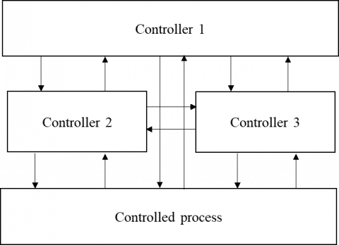
In the STPA, the hierarchical control structure is not a physical control structure, but a system model with control actions and feedbacks, which mainly include the controlled process, and a hierarchy of controllers. The hierarchical control structure of the STPA is shown in Figure 1 [7], where the downward arrows stand for control actions, while the upward stand for feedbacks. It is advisable to define the control actions based on the responsibilities of the controllers, and derive the feedbacks from the control actions and the responsibilities of the controllers [7, 8].
Figure 1. A generic hierarchical control structure [7]
Note that Figure 1 only represents one generic hierarchical control structure, in which Controller 1 has the highest level of authority, and Controllers 2 and 3 have lower but the same level of authority. The horizontal arrows between Controllers 2 and 3 do not represent control actions or feedbacks, but the communication between the two controllers.
The hierarchical control structure can also be refined and detailed, in view of the different subsystems of the partial system selected for the study [7, 8].
3.1.4 Building the UCA table with causes
Leveson and Thomas defined an UCA as “a control action that, in a particular context and worst-case environment, will lead to a hazard” [7, 8], and enumerated the generation paths of UCAs [7, 8]:
-Not providing the control action leads to a hazard.
-Providing the control action leads to a hazard.
-A potentially safe control action is provided too early, too late, or in the wrong order.
-The control action lasts too long or is stopped too soon.
Note that the third and fourth paths are related to the timing and duration of the control action, while the first two paths are related to not providing a control action at all, or providing a control action that leads to a hazard. Table 1 provides a representative UCA table with UCAs to be written under each category, causes for these UCAs, and controller constraints. Some UCA tables only display the UCAs under each category. The causes or controller constraints are provided separately.
Table 1. A representative UCA table [54]
|
Path 1 |
Path 2 |
Path 3 |
Path 4 |
|
UCA-1 [H-1, H-5] |
UCA-2 [H-6] |
UCA-3 [H-7] |
UCA-4 [H-2] |
|
… |
… |
… |
… |
|
Causes |
Causes |
Causes |
Causes |
|
Controller constraints [UCA-1] |
Controller constraints [UCA-2] |
Controller constraints [UCA-3] |
Controller constraints [UCA-4] |
A separate UCA table like Table 1 can be prepared for every control function. In such a table, several UCAs can be defined for each category, and be linked to high-level system hazards. The defined UCAs should be translated into controller constraints, which are the required controller behaviors to prevent the UCAs [7, 8]. The causes (loss scenarios) of the UCAs should also be identified, and provided in the table clearly. The two main causes, namely, unsafe controller behavior, and inadequate feedback and other inputs, should be detailed for each UCA [7, 8]. During the cause identification, the physical control structure including sensors and actuators can also be considered [7, 8]. Before preparing the UCA tables, it is also possible to classify controllers as technical controllers or human controllers [7].
3.1.5 Constructing the hierarchy of preventive and protective measures
The hierarchy of preventive and protective measures, a term generally used for the OSH, can be extended to general system reliability, including process reliability and OSH.
Table 2 lists the four basic hierarchy levels with examples in the second column. The higher the hierarchy level, the better the effectiveness of the measure, and the fewer the total cost. Accordingly, hazard elimination is the most effective measure with the minimum total cost, while damage reduction is the least effective one with the maximum total cost.
Table 2. Hierarchy of preventive and protective measures [8]
|
Hierarchy level |
Examples |
|
Hazard elimination |
Elimination, substitution, and simplification |
|
Hazard reduction |
Barriers, and failure minimization |
|
Hazard control |
Exposure reduction, and isolation |
|
Damage reduction |
Application following the occurrence of an accident or a disease |
To briefly summarize the STPA, Figure 2 outlines the connections between STPA outputs. The hierarchical control structure is not displayed, for it is related to each output, as suggested by Leveson and Thomas [7].
Figure 2. Connections between STPA outputs [7]
It can be clearly seen that, each STPA output can be traced to another output. Many accidents may occur due to the ineffective and ambiguous definition of responsibilities. Hence, it is highly recommended to define the responsibilities, although this is not a must-to-do task.
3.2 FMEA
The FMEA was developed in the 1960s by the NASA. Since then, the strategy has gained popularity in risk assessment of aerospace, nuclear power plants, and automotive industry. There are several types of FMEA, including system FMEA, function FMEA, design FMEA, and process FMEA [28].
As an inductive method, the FMEA focuses on identifying the modes, effects, and causes of potential failures, considering their RPN values [28]. Failure mode is a very basic term in the FMEA. It refers to a description of the fault, i.e., the way to observe the fault, so that the failures can be apparent and observable to indicate a problem in the system [55]. Failure mode identification is a time-consuming yet crucial step of the FMEA [28].
The representative FMEA table is given as Table 3, where F is the selected function of the target system; PFM is the potential failure mode; PFE is the potential failure effects, namely, minor damage, and total system breakdown; PFC is the potential failure causes, technical or organizational; RA is the recommended actions, whose application underpins the evaluation of system improvement; O is occurrence, i.e., the probability or frequency of a failure mode under its corresponding failure cause; S is severity, i.e. the degree of the potential failure effect [28]; D is detection, which depends on the probability of detecting a failure cause easily before it leads to a failure [28].
Table 3. Representative FMEA table [28]
|
F |
PFM |
PFE |
PFC |
O |
S |
D |
RPN |
RA |
|
|
|
|
|
|
|
|
|
|
The values of O, S, and D generally fall in [1, 10]. The RPN can be calculated by:
RPN $=0 \times S \times D$ (1)
In the extreme cases, an RPN value can be 1 × 1 × 1 = 1 or 10 × 10 × 10 = 1,000. The mean RPN can be calculated as 5 × 5 × 5 =125. Once the FMEA table is prepared, it is necessary to rank the potential failure modes, as well as the corresponding effects and causes, by the RPN. The failure modes with the values O>8, S>8, \text { and } D>8 should be observed separately [28]. After implementing the recommended actions, the new values can be assigned to O, S, and D, and the revised RPN values can be calculated to compare the updated RPN values with the former values. The responsibility assignments and target completion dates can be added as two columns to the representative FMEA table in Table 3 [28].
As a specific type of the FMEA, system FMEA covers five steps [28]: (1) Defining the target system structure, identifying the subsystems and components, and building the hierarchy of system elements; (2) Defining functions and building function structures by function trees and several other approaches; (3) Identifying potential failure modes, effects, and causes for each system element; (4) Performing risk assessment, including assigning values to O, S, and D, (5) Prioritizing and evaluating risks as explained for the general FMEA.
The application of epoxy resin is a common operation in many construction projects. Both process reliability and OSH should be assured during the application of STPA and FMEA.
4.1 STPA
4.1.1 Defining system boundaries and goals
As part of the target system, the subsystem related to the application of epoxy resin was considered. The basic system goals for the operation in a construction project can be defined as in Table 4.
Table 4. Basic system goals
|
System goal |
Definition |
|
SG-1 |
Maximizing the application quality |
|
SG-2 |
Maximizing the cost-effectiveness of the application |
|
SG-3 |
Maximizing the OSH |
|
SG-4 |
Maximizing consumer satisfaction |
The basic system goals can be independent of each other. The STPA mainly aims to trace the results of STPA analysis to high-level system losses, which are traceable to system goals. As indicated by Leveson and Thomas [7], it is possible to rank and prioritize the high-level system losses, and system goals. The system goals can be measured by predefined key performance indicators (KPIs), such as the consumer satisfaction score.
4.1.2 Identifying high-level system losses and hazards, and system-level constraints
The high-level system losses, high-level system hazards, and system-level constraints are displayed in Tables 5-7, respectively.
Table 5. High-level system losses
|
High-level system loss |
Definition |
|
L-1 |
Inferior quality [SG-1] |
|
L-2 |
Rework and loss of material [SG-1, SG-2] |
|
L-3 |
Ergonomic injury to workers [SG-3] |
|
L-4 |
Ill health of workers [SG-3] |
|
L-5 |
Loss of consumer satisfaction [SG-4] |
|
L-6 |
Application not finished on time [SG-2, SG-4] |
Table 6. High-level system hazards
|
High-level system hazard |
Definition |
|
H-1 |
Poorly planned worker selection and training [L-1, L-2, L-4, L-6] |
|
H-2 |
Poorly planned and/or implemented measures for OSH [L-3, L-4] |
|
H-3 |
Awkward worker posture caused by the work design [L-3] |
|
H-4 |
Poorly prepared concrete base before the epoxy resin application [L-1, L-2, L-5, L-6] |
|
H-5 |
Improper air temperature and moisture [L-1, L-2, L-4, L-5, L-6] |
|
H-6 |
Poorly prepared material mixture [L-1, L-2, L-5, L-6] |
|
H-7 |
Inappropriate processing time and curing time [L-1, L-2, L-5, L-6] |
|
H-8 |
Insufficient ventilation of the environment [L-1, L-2, L-4, L-5, L-6] |
As given in Table 6, processing time and curing time are part of H-7. The former term refers to the time that the epoxy resin can be processed after the mixture of the two components. The latter term refers to the time until the epoxy resin is cured, i.e., the resin reaches a hard, dimensionally stable near-net-shape component, after the mixture of the two components [56].
Table 7. System-level constraints
|
System-level constraint |
Definition |
|
SC-1 |
Worker selection and training must be well-planned. [H-1] |
|
SC-2 |
An effective system must be developed for OSH, and the workers must be encouraged to obey OSH-related measures, especially during indoor operations. [H-2] |
|
SC-3 |
Process and equipment design must be done to avoid awkward worker postures. [H-3] |
|
SC-4 |
All the preparation steps for the concrete base must be clearly defined and implemented. [H-4] |
Table 7. System-level constraints (cont.)
|
System-level constraint |
Definition |
|
SC-5 |
Air temperature and moisture must be continuously regulated at levels appropriate for epoxy resin application and OSH. [H-2, H-5] |
|
SC-6 |
The materials selection and their mixture must be well-planned and implemented. [H-2, H-6, H-7] |
|
SC-7 |
Ventilation of the environment must be made regularly. [H-2, H-8] |
4.1.3 Setting up the hierarchical control structure
Figure 3 shows the hierarchical control structure for the subsystem of epoxy resin application. The subsystem including epoxy resin application basically covers the application area, materials and equipment, as well as workers. For clarity, the control actions and feedbacks are numbered in Figure 3, and explained in Table 8.
Figure 3. Hierarchical control structure
The subsystem including epoxy resin application can be understood as a partial system of contractor or subcontractor. If it is a partial system of subcontractor, then the subcontractor is inherent in that subsystem. Note that the engineering team of project owner, and project management team (an independent company) are assumed to work collaboratively, without taking any control action against each other. Hence, the two teams must fall on the same level of hierarchical control, and communicate with each other, with no control action or feedback between them. That is why the arrows between them are not numbered. In addition, all controllers are human, and may differ in the process models and values for the controlled process.
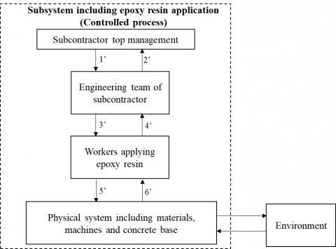
Since this research intends to analyze the subsystem including epoxy resin application, the hierarchical control structure (Figure 3) was refined by zooming in the controlled process, i.e., the subsystem including epoxy resin application. The refined partial hierarchical control structure is displayed in Figure 4, where the subcontractor is involved in the subsystem including epoxy resin application.
Like those in Figure 3, the control actions and feedbacks in Figure 4 are numbered. The system boundaries in Figure 4 restrict our consideration to the subsystem including epoxy resin application, as the controlled process interacting with the environment. The two arrows are not numbered, for the subsystem-environment interaction is not covered in this study.
Table 8. Control actions and feedbacks
|
Control action/feedback |
Definition |
|
1 |
Operational requirements |
|
2 |
Information of progress |
|
3 |
Project management requirements |
|
4 |
Information of progress |
|
5 |
Strategic capability requirements |
|
6 |
Confirmation of capability |
|
7 |
Material, application and subcontractor requirements |
|
8 |
Confirmation of requirements |
|
9 |
Control of application |
|
10 |
Progress reports, and incident reports |
|
11 |
Financial requirements |
|
12 |
Progress reports |
|
13 |
Information about quality and business process management requirements |
|
14 |
Status reports about quality and business process management |
|
15 |
Procedures about application |
|
16 |
Progress reports, and incident reports |
Figure 4. Refined partial hierarchical control structure
The control actions and feedbacks for the refined partial hierarchical control structure are provided in Table 9.
Table 9. Control actions and feedbacks for subsystem
|
Control action/feedback |
Definition |
|
1’ |
Materials, machine, quality, operations, and OSH-related requirements for epoxy resin application |
|
2’ |
Information about the status of application |
|
3’ |
Procedures for the application |
|
4’ |
Status reports, and incidents reports |
|
5’ |
Application |
|
6’ |
Feedback about the status |
The refined partial hierarchical control structure includes the physical system involving the resources for epoxy resin application, the environment, as well as the controllers within the subsystem. The environmental factors, e.g., air temperature, moisture, and ventilation directly bear on the physical system. In return, the physical system may affect the environment.
4.1.4 Setting up the UCA table with causes
Two control actions were selected from Table 9 for the refined partial hierarchical control structure in Figure 4. Then, the UCA tables with causes were set up for these two control actions (Tables 10 and 11).
It can be seen clearly from Table 10 that all UCAs can be traced back to hazards, which is a crucial step to interrelate different outcomes of the STPA. The causes explain why UCAs may occur, and are basically generated in the light of unsafe controller behaviors, such as insufficient knowledge or experience, inadequate mental models, and improper feedback/information processing. The controller constraints are almost the direct translation of the UCAs in the form of enforcement on the behavior of the controller.
The UCAs in Table 10 were rather similar to those in Table 11. The only difference in that the control actions in Table 10 are from the top management of the subcontractor to their engineering team, while those in Table 11 are from the engineering team of the subcontractor to the workers applying epoxy resin.
Table 10. UCA table with causes for control action 1’
|
Path 1 |
Path 2 |
Path 3 |
Path 4 |
|
UCA1’-1: Some requirements are missing. [H-1, H-2, H-3, H-4, H-5, H-6, H-7, H-8] |
UCA1’-2: Some requirements are incorrect, not specific or not clear. [H-1, H-2, H-3, H-4, H-5, H-6, H-7, H-8] |
UCA1’-3: Some requirements are provided after the start of the application process. [H-1, H-2, H-3, H-4, H-5, H-6, H-7, H-8] UCA1’-4: Some requirements are immature, and specified before the project is detailed. [H-1, H-2, H-3, H-4, H-5, H-6, H-7, H-8] |
N/A |
|
Causes: -Incomplete information, incorrect data, and insufficient experience -Organizational problems arising from the responsibility for other projects |
Causes: -Incomplete information, incorrect data, and insufficient experience or technical knowledge. |
Causes: -Incomplete information, incorrect data, and insufficient experience or technical knowledge. |
|
|
|
-Mental model regarding the assumption that the requirements are correct, specific and clear. - Lack of adaptation to the changing requirements, such as the updates in the material mixture |
-Updates about the decision of the selection of the supplier of the materials after the application starts. -OSH related issues, such as accidents, and diseases -Immature decision about the material and/or supplier. -Updates driven by the latest technological changes. |
|
Table 10. UCA table for control action 1’ (cont.)
|
Path 1 |
Path 2 |
Path 3 |
Path 4 |
|
Controller constraints: The requirements must be checked for completeness. [UCA1’-1] |
Controller constraints: The requirements must be checked for correctness, specificity, and unambiguity. [UCA1’-2] |
Controller constraints: The requirements must be provided before the start of the application process. [UCA1’-3] The requirements must not be provided before the project is fully detailed. [UCA1’-4] |
N/A |
Table 11. UCA table with causes for control action 3’
|
Path 1 |
Path 2 |
Path 3 |
Path 4 |
|
UCA3’-1: Some parts of the procedures are incomplete. [H-1, H-2, H-3, H-4, H-5, H-6, H-7, H-8] |
UCA3’-2: Some parts of the procedure are incorrect, not specific and not clear for the workers. [H-1, H-2, H-3, H-4, H-5, H-6, H-7, H-8] |
UCA3’-3: Some updates of the procedures are provided after the start of the application. [H-4, H-5, H-6, H-7, H-8] |
N/A |
|
Causes: -Incomplete information, and insufficient technical knowledge. -Incomplete requirements from the top management of the subcontractor to their engineering team. |
Causes: -Mental model regarding the assumption that the procedures are specific and clear for the workers. -Incomplete information, insufficient technical knowledge, and lack of training from the suppliers. |
Causes: -Changes in the requirements from the top management of the subcontractor to their engineering team. -Changes in the materials, the availability of materials, and the supplier of the materials. |
|
|
Controller constraints: All parts of the procedures must be complete. [UCA3’-1] |
Controller constraints: The procedures must be correct, specific, and clear for the workers. [UCA3’-2] |
Controller constraints: The updates of the procedures should be restricted after the start of the application. [UCA3’-3] |
N/A |
4.1.5 Constructing the hierarchy of preventive and protective measures
As the final step of the STPA, the hierarchy of preventive and protective measures was constructed for the epoxy resin application (Table 12), although this step is not a must in many STPA applications.
Table 12. Hierarchy of preventive and protective measures
|
Hierarchy level |
Examples |
|
Hazard elimination |
Automation, and substitution |
|
Hazard reduction |
Excellent business process management |
|
Hazard control |
Wearing appropriate personal protective equipment (PPE), training, and ventilation |
|
Damage reduction |
Alternative work, and worker welfare |
As shown in Table 12, automation can eliminate most OSH related hazards and risks, and prevent the hazards of inferior quality, and rework and loss of material. However, automation may bring some OSH-related problems, because the workers need to occasionally interact with the automated machines for supervision. Substitution may be implemented as replacing two-part products with single-component epoxy systems, using polyamide and cycloaliphatic amine as curing agents, and adopting resins with a high molecular weight [57].
Under the hierarchical control structure, the excellent business process management of each component, with clearly defined responsibilities, can considerably decrease any type of hazard in the system.
Wearing appropriate PPE, including respiratory equipment, safety goggles, protective clothing, and disposable gloves, is very important to control and minimize health effects to the workers. It is also essential to train the workers regarding hand washing techniques and personal hygiene to prevent dermatitis, choosing and using the PPE correctly, and making ventilation correctly [57]. Two types of ventilation are recommended by the Center for Construction Research and Training (CPWR) [57]: LEV (e.g., dust collectors) and general dilution (e.g., portable exhaust fans).
Worker welfare should be maintained whenever any accident occurs, or a worker has a disease such as dermatitis. If a worker suffers from severe health effects because of working in an environment with epoxy resin application, he/she should be assigned an alternative work.
4.2 FMEA
The reliability of the subsystem of epoxy resin application was analyzed by the FMEA. The first step of the FMEA is to identify the potential failure modes, and detect the possible failure effects and causes (Table 13). Here, this step is performed by the help of an expert in the area.
Poor work design is related to the organization of the activities within the work environment. Next, O, S, and D values were assigned to the potential failure modes, and the RPN values were calculated (Table 14). This step was also performed by the help of an expert in the area. The potential failure causes in Table 13 can be removed as recommended actions.
As shown in Table 14, the potential failure modes like air bubbles, and micro holes had the highest RPN values, indicating that these failures should be treated with the highest priority by taking recommended actions. The potential causes for failure modes regarding the OSH should also be prevented with the highest priority, despite their low RPN values.
As evident from the application, the FMEA needs to collect expert knowledge and opinions, and, in most cases, exhibits as a consensus of expert opinions regarding all the steps of FMEA, including the assignment of the scales to O, S, and D.
Table 13. Potential failure modes, effects and causes
|
Potential failure mode |
Potential failure effect |
Potential failure cause |
|
1. Not hardening |
Inferior quality, and rework and loss of material |
Inappropriate air temperature and moisture, and inappropriate mixing of the product |
|
2. Not sticking |
Inferior quality, and rework and loss of material |
Inappropriate preparation of the base structure, and uneven distribution of epoxy resin |
|
3. Inadequate shining |
Inferior quality, and rework and loss of material |
Unfavourable climatic conditions of the environment |
|
4. Insufficient curing time |
Inferior quality, and rework and loss of material |
Inappropriate air temperature and moisture |
|
1. Air bubbles |
Inferior quality, and rework and loss of material |
Inappropriate mixing of the product |
|
2. Micro holes |
Inferior quality, and rework and loss of material |
Using epoxy resin with fibreglass |
|
3. Unclear surface |
Inferior quality, and rework and loss of material |
Unclean environment, including unclean tools |
|
4. Wavy surface |
Inferior quality, and rework and loss of material |
Inappropriate preparation of the base structure, and uneven distribution of epoxy resin |
|
5. Dermatitis of workers |
Health problems, bad quality of work, and absent days of workers |
Material mixture, inadequate ventilation, inadequate usage of PPE, and poor work design |
|
6. Respiratory problems of workers |
Health problems, bad quality of work, and absent days of workers |
Material mixture, inadequate ventilation, inadequate usage of PPE, and poor work design |
|
7. Ergonomic injury to workers |
Health problems, bad quality of work, and absent days of workers |
Awkward postures for a long time, and poor work design |
Table 14. Potential failure modes, and O, S, D, and RPN values
|
Potential failure mode |
O |
S |
D |
RPN |
|
1. Not hardening |
5 |
10 |
4 |
200 |
|
2. Not sticking |
|
|
|
|
|
3. Inadequate shining |
5 |
7 |
4 |
140 |
|
4. Insufficient curing time |
5 |
10 |
5 |
250 |
|
5. Air bubbles |
8 |
10 |
4 |
320 |
|
6. Micro holes |
10 |
8 |
4 |
320 |
|
7. Unclear surface |
7 |
7 |
4 |
196 |
|
8. Wavy surface |
8 |
8 |
4 |
256 |
|
9. Dermatitis problems of workers |
5 |
7 |
4 |
140 |
|
10. Respiratory problems of workers |
5 |
10 |
4 |
200 |
|
11. Ergonomic injury to workers |
5 |
8 |
4 |
160 |
Wu et al. [58] reviewed the literature on the FMEA in manufacturing industry, and presented several means of integrating expert opinions with the FMEA, using fuzzy logic, and many other approaches. The FMEA can be integrated with expert systems for an automated and more sophisticated analysis. But there are some differences between the FMEA and expert systems. An expert system is a general knowledge-based system, which collects and structures the expert knowledge systematically by software, allowing the user to retrieve the knowledge easily. By contrast, the FMEA is a specific risk assessment technique, in which the failure modes, effects, and detectability are analyzed and scaled, and the failures are ranked and prioritized to allocate the necessary resources for failure prevention.
This paper analyzes the reliability of the subsystem of epoxy resin application by STPA and FMEA. The STPA focuses on the hierarchical control structures, UCAs, and causes within these structures. Meanwhile, the FMEA stresses the potential failure modes, causes, and effects, as well as RPN values. From different views, the analysis results of the two techniques were incorporated to eliminate, reduce, or control the hazards. To the best of our knowledge, this is the first paper on the joint utilization of STPA and FMEA to the application of epoxy resin. Considering process reliability, both techniques were employed to maximize the quality, cost-effectiveness, and consumer satisfaction of the application, as well as the OSH.
The STPA was implemented in the following manner: After defining the system goals, high-level system losses, high-level system hazards, and system-level constraints, the basic hierarchical control structure was established, and the refined hierarchical control structure was derived for the subsystem including epoxy resin application. Next, the UCAs, causes, and controller constraints were defined for two selected control actions of the refined structure. In future, more refined hierarchical control structures will be derived from the basic structure, and all control actions for the refined structures will be analyzed for a thorough evaluation.
During the use of the FMEA, the potential failure modes, causes, and effects were defined for the epoxy resin application with the help of an expert in the area, along with the corresponding RPN values. In future, the O, S, and D values will be assigned with a group of experts, aiming to improve the reliability of RPN values. Moreover, the fuzzy data will be dealt with by fuzzy FMEA techniques.
In the next research, the causal analysis based on systems theory (CAST), another tool for STAMP, could be called to examine the accidents/incidents/quality problems that have occurred, and to identify their causes. Other conventional techniques like FTA and root cause analysis can also be applied independently or as a hybrid model, enabling the collection, combination, and comparison of different outcomes from various techniques.
[1] Parameswaranpillai, J., Pulikkalparambil, H., Rangappa, S.M., Siengchin, S. (2021). Epoxy Composites: Fabrication, Characterization and Applications. Wiley-VCH GmbH.
[2] Lei, Y., Cao, X. (2015). Preparation of epoxy-resin concrete using microwave curing method and its pavement performance evaluation. Journal of Materials in Civil Engineering, 27(8): 1-7. https://doi.org/10.1061/(ASCE)MT.1943-5533.0001179
[3] OSHA Europa. Occupational Exposure to Epoxy Resins. https://osha.europa.eu/en/themes/dangerous-substances/practical-tools-dangerous-substances/occupational-exposure-epoxy-resins, https://oshwiki.eu/wiki/Occupational_exposure_to_epoxy_resins, accessed on Aug. 23, 2021.
[4] Towler, G., Sinnott, R. (2022). Chapter 10 - Safety and loss prevention. In: Towler, G., Sinnott, R. (eds) Chemical Engineering Design. Butterworth-Heinemann.
[5] Crawley, F. (2020). 14 - Event tree analysis. In: Crawley, F. (ed) A Guide to Hazard Identification Methods. Elsevier. https://doi.org/10.1016/C2018-0-05378-5
[6] Subramanian N. (2021). Root cause analysis. In: Jajodia S., Samarati P., Yung M. (eds) Encyclopedia of Cryptography, Security and Privacy. Springer, Berlin Heidelberg. https://doi.org/10.1007/978-3-642-27739-9
[7] Leveson, N.G., Thomas, J.P. (2018). STPA Handbook. https://psas.scripts.mit.edu/home/get_file.php?name=STPA_handbook.pdf, accessed on Aug. 23, 2021.
[8] Leveson, N.G. (2011). Engineering a Safer World. Systems Thinking Applied to Safety. The MIT Press. https://doi.org/10.7551/mitpress/8179.001.0001
[9] Bensaci, C., Zennir, Y., Pomorski, D., Innal, F., Liu, Y. (2021). Distributed vs. hybrid control architecture using STPA and AHP - Application to an autonomous mobile multi-robot system. International Journal of Safety and Security Engineering, 11(1): 1-12. https://doi.org/10.18280/ijsse.110101
[10] Cui, L.J., Cong, J.P., Chen, H.R., Ren, B. (2020). Safety analysis and simulation validation of hose whipping phenomenon in air refueling. International Journal of Safety and Security Engineering, 10(5): 601-608. https://doi.org/10.18280/ijsse.100503
[11] Li, M., Yan, F., Niu, R., Xiang, N. (2021). Identification of causal scenarios and application of leading indicators in the interconnection mode of urban rail transit based on STPA. Journal of Rail Transport Planning & Management, 17: 1-13. https://doi.org/10.1016/j.jrtpm.2021.100238
[12] Bas, E. (2020). STPA methodology in a socio-technical system of monitoring and tracking diabetes mellitus. Applied Ergonomics, 89: 1-13. https://doi.org/10.1016/j.apergo.2020.103190
[13] Chen, S., Khastgir, S., Jennings, P. (2021). Analyzing national responses to COVID-19 pandemic using STPA. Safety Science, 138: 1-11. https://doi.org/10.1016/j.ssci.2021.105195
[14] Shin, J., Choi, J.G., Lee, J.W., Lee, C.K., Song, J.G., Son, J.Y. (2021). Application of STPA-SafeSec for a cyber-attack impact analysis of NPPs with a condensate water system test-bed. Nuclear Engineering and Technology, 53(10): 3319-3326. https://doi.org/10.1016/j.net.2021.04.031
[15] Dghaym, D., Hoang, T.S., Turnock, S.R., Butler, M., Downes, J., Pritchard, B. (2021). An STPA-based formal composition framework for trustworthy autonomous maritime systems. Safety Science, 136: 1-11. https://doi.org/10.1016/j.ssci.2020.105139
[16] de Souza, N.P., de Azevedo Castro César, C., de Melo Bezerra, J., Hirata, C.M. (2020). Extending STPA with STRIDE to identify cybersecurity loss scenarios. Journal of Information Security and Applications, 55: 1-13. https://doi.org/10.1016/j.jisa.2020.102620
[17] Chaal, M., Valdez Banda, O.A., Glomsrud, J.A., Basnet, S., Hirdaris, S., Kujala, P. (2020). A framework to model the STPA hierarchical control structure of an autonomous ship. Safety Science, 132: 1-15. https://doi.org/10.1016/j.ssci.2020.104939
[18] Sultana, S., Okoh, P., Haugen, S., Vinnem, J.E. (2019). Hazard analysis: Application of STPA to ship-to-ship transfer of LNG. Journal of Loss Prevention in the Process Industries, 60: 241-252. https://doi.org/10.1016/j.jlp.2019.04.005
[19] Rejzek, M., Hilbes, C. (2018). Use of STPA as a diverse analysis method for optimization and design verification of digital instrumentation and control systems in nuclear power plants. Nuclear Engineering and Design, 331: 125-135. https://doi.org/10.1016/j.nucengdes.2018.02.030
[20] Baybutt, P. (2021). On the need for system-theoretic hazard analysis in the process industries. Journal of Loss Prevention in the Process Industries, 69: 1-10. https://doi.org/10.1016/j.jlp.2020.104356
[21] Kaya, G.K. (2021). A system safety approach to assessing risks in the sepsis treatment process. Applied Ergonomics, 94: 1-13. https://doi.org/10.1016/j.apergo.2021.103408
[22] Abdulkhaleq, A., Wagner, S., Leveson, N. (2015). A comprehensive safety engineering approach for software-intensive systems based on STPA. Procedia Engineering, 128: 2-11. https://doi.org/10.1016/j.proeng.2015.11.498
[23] Yang, C. (2014). Software safety testing based on STPA. Procedia Engineering, 80: 399-406. https://doi.org/10.1016/j.proeng.2014.09.097
[24] Silvis-Cividjian, N., Verbakel, W., Admiraal, M. (2020). Using a systems-theoretic approach to analyze safety in radiation therapy-first steps and lessons learned. Safety Science, 122: 1-10. https://doi.org/10.1016/j.ssci.2019.104519
[25] Yamaguchi, S., Thomas, J. (2019). A system safety approach for tomographic treatment. Safety Science, 118: 772-782. https://doi.org/10.1016/j.ssci.2019.05.041
[26] Zhou, X.Y., Liu, Z.J., Wang, F.W., Wu, Z.L. (2021). A system-theoretic approach to safety and security co-analysis of autonomous ships. Ocean Engineering, 222: 1-14. https://doi.org/10.1016/j.oceaneng.2021.108569
[27] Jamot, D.G.C., Park, J.Y. (2019). System theory based hazard analysis for construction site safety: A case study from Cameroon. Safety Science, 118: 783-794. https://doi.org/10.1016/j.ssci.2019.06.007
[28] Bertsche, B. (2008). Chapter 4 FMEA- Failure Mode and Effects Analysis. In: Bertsche, B. (ed) Reliability in Automotive and Mechanical Engineering. Springer-Verlag, Berlin Heidelberg. https://doi.org/10.1007/978-3-540-34282-3
[29] Huang, J., You, J.X., Liu, H.C., Song, M.S. (2020). Failure mode and effect analysis improvement: A systematic literature review and future research agenda. Reliability Engineering & System Safety, 199: 1-12. https://doi.org/10.1016/j.ress.2020.106885
[30] Rozak, A., Jaqin, C., Hasbullah, H. (2020). Increasing overall equipment effectiveness in automotive company using DMAIC and FMEA method. Journal Européen des Systèmes Automatisés, 53(1): 55-60. https://doi.org/10.18280/jesa.530107
[31] Kusrini, E., Hanim, K. (2021). Analysis of compliance and supply chain security risks based on ISO 28001 in a logistic service provider in Indonesia. International Journal of Safety and Security Engineering, 11(2): 135-142. https://doi.org/10.18280/ijsse.110202
[32] Maryani, E., Purba, H.H., Sunadi. (2021). Analysis of aluminium alloy wheels product quality improvement through DMAIC method in casting process: A case study of the wheel manufacturing industry in Indonesia. Journal Européen des Systèmes Automatisés, 54(1): 55-62. https://doi.org/10.18280/jesa.540107
[33] Wang, L., Yan, F., Wang, F., Li, Z. (2021). FMEA-CM based quantitative risk assessment for process industries-A case study of coal-to-methanol plant in China. Process Safety and Environmental Protection, 149: 299-311. https://doi.org/10.1016/j.psep.2020.10.052
[34] Li, H., Díaz, H., Guedes Soares, C. (2021). A failure analysis of floating offshore wind turbines using AHP-FMEA methodology. Ocean Engineering, 234: 1-15. https://doi.org/10.1016/j.oceaneng.2021.109261
[35] Wang, W., Liu, X., Chen, X., Qin, Y. (2019). Risk assessment based on hybrid FMEA framework by considering decision maker’s psychological behavior character. Computers & Industrial Engineering, 136: 516-527. https://doi.org/10.1016/j.cie.2019.07.051
[36] Peeters, J.F.W., Basten, R.J.I., Tinga, T. (2018). Improving failure analysis efficiency by combining FTA and FMEA in a recursive manner. Reliability Engineering & System Safety, 172: 36-44. https://doi.org/10.1016/j.ress.2017.11.024
[37] Yousefi, S., Alizadeh, A., Hayati, J., Baghery, M. (2018). HSE risk prioritization using robust DEA-FMEA approach with undesirable outputs: A study of automotive parts industry in Iran. Safety Science, 102: 144-158. https://doi.org/10.1016/j.ssci.2017.10.015
[38] Mangeli, M., Shahraki, A., Saljooghi, F.H. (2019). Improvement of risk assessment in the FMEA using nonlinear model, revised fuzzy TOPSIS, and support vector machine. International Journal of Industrial Ergonomics, 69: 209-216. https://doi.org/10.1016/j.ergon.2018.11.004
[39] Fattahi, R., Khalilzadeh, M. (2018). Risk evaluation using a novel hybrid method based on FMEA, extended MULTIMOORA, and AHP methods under fuzzy environment. Safety Science, 102: 290-300. https://doi.org/10.1016/j.ssci.2017.10.018
[40] Gaur, K. (2019). Systematic and quantitative assessment and application of FMEA and lean six sigma for reducing nonproductive time in operation theatre of a tertiary care hospital in a metropolis. Perioperative Care and Operating Room Management, 16: 1-4. https://doi.org/10.1016/j.pcorm.2019.100075
[41] Liu, C.T., Hwang, S.L., Lin, IK. (2013). Safety analysis of combined FMEA and FTA with computer software assistance – Take photovoltaic plant for example. IFAC Proceedings Volumes, 46(9): 2151-2155. https://doi.org/10.3182/20130619-3-RU-3018.00370
[42] Almannai, B., Greenough, R., Kay, J. (2008). A decision support tool based on QFD and FMEA for the selection of manufacturing automation technologies. Robotics and Computer-Integrated Manufacturing, 24(4): 501-507. https://doi.org/10.1016/j.rcim.2007.07.002
[43] Scipioni, A., Saccarola, G., Centazzo, A., Arena, F. (2002). FMEA methodology design, implementation and integration with HACCP system in a food company. Food Control, 13(8): 495-501. https://doi.org/10.1016/S0956-7135(02)00029-4
[44] Mariajayaprakash, A., Senthilvelan, T. (2013). Failure detection and optimization of sugar mill boiler using FMEA and Taguchi method. Engineering Failure Analysis, 30: 17-26. https://doi.org/10.1016/j.engfailanal.2012.12.010
[45] Ribas, J.R., Severo, J.C.R., Guimarães, L.F., Perpetuo, K.P.C. (2021). A fuzzy FMEA assessment of hydroelectric earth dam failure modes: A case study in Central Brazil. Energy Reports, 7: 4412-4424. https://doi.org/10.1016/j.egyr.2021.07.012
[46] Abdelgawad, M., Fayek, A.R. (2010). Risk management in the construction industry using combined fuzzy FMEA and fuzzy AHP. Journal of Construction Engineering and Management, 136(9): 1028-1036. https://doi.org/10.1061/(ASCE)CO.1943-7862.0000210
[47] Rahimi, Y., Tavakkoli-Moghaddam, R., Iranmanesh, S.H., Vaez-Alaei, M. (2018). Hybrid approach to construction project risk management with simultaneous FMEA/ISO 31000/evolutionary algorithms: Empirical optimization study. Journal of Construction Engineering and Management, 144(6): 1-15. https://doi.org/10.1061/(ASCE)CO.1943-7862.0001486
[48] Abdelgawad, M., Fayek, A.R. (2012). Comprehensive hybrid framework for risk analysis in the construction industry using combined failure mode and effect analysis, fault trees, event trees, and fuzzy logic. Journal of Construction Engineering and Management, 138(5): 642-651. https://doi.org/10.1061/(ASCE)CO.1943-7862.0000471
[49] Ashraf, F.U., Johnson, P.A. (2016). Assessing relative risk for the failure modes of a bridge scour countermeasure. Journal of Bridge Engineering, 21(5): 1-10. https://doi.org/10.1061/(ASCE)BE.1943-5592.0000899
[50] Putcha, C., Dutta, S., Rodriguez, J. (2020). Risk priority number for bridge failures. Practice Periodical on Structural Design and Construction, 25(2): 1-5. https://doi.org/10.1061/(ASCE)SC.1943-5576.0000480
[51] Al-Humaidi, H.M., Tan, F.H. (2012). Using fuzzy failure mode effect analysis to model cave-in accidents. Journal of Performance of Constructed Facilities, 26(5): 702-719. https://doi.org/10.1061/(ASCE)CF.1943-5509.0000276
[52] Yazdani, M., Abdi, M.R., Kumar, N., Keshavarz-Ghorabaee, M. (2019). Improved decision model for evaluating risks in construction projects. Journal of Construction Engineering and Management, 145(5): 1-13. https://doi.org/10.1061/(ASCE)CO.1943-7862.0001640
[53] Kan, C., Anumba, C.J., Fang, Y., Messner, J.I. (2018). Use of analytical tools to mitigate mobile crane-related failures. Construction Research Congress: Safety and Disaster Management, 184-195. https://doi.org/10.1061/9780784481288.019
[54] Mahajan, H.S., Bradley, T., Pasricha, S. (2017). Application of systems theoretic process analysis to a lane keeping assist system. Reliability Engineering & System Safety, 167: 177-183. https://doi.org/10.1016/j.ress.2017.05.037
[55] Rausand, M., Hoyland, A. (2004). System Reliability Theory Models, Statistical Methods, and Applications. Wiley Series in Probability and Statistics. https://doi.org/10.1002/9781119373940
[56] Crowson, R. (2006). The Handbook of Manufacturing Engineering. Parts Fabrication. Principles and Process. CRC Taylor & Francis Group.
[57] The Center for Construction Research and Training. CPWR. Working with Epoxy Resin Systems in Construction. Best Practices Guide to Skin Protection. https://www.elcosh.org/document/2088/d001103/Working+with+Epoxy+Resin+Systems+in+Construction+-+Best+Practices+Guide+to+Skin+Protection.html, accessed on Aug. 23, 2021.
[58] Wu, Z., Liu, W., Nie, W. (2021). Literature review and prospect of the development and application of FMEA in manufacturing industry. International Journal Advanced Manufacturing Technology, 112: 1409-1436. https://doi.org/10.1007/s00170-020-06425-0