Lijie Cui | Jiping Cong* | Haoran Chen | Bo Ren
© 2020 IIETA. This article is published by IIETA and is licensed under the CC BY 4.0 license (http://creativecommons.org/licenses/by/4.0/).
OPEN ACCESS
This paper aims to identify the main cause of the hose whipping phenomenon (HWP) in air refueling, and come up with effective preventive measures. The system-theoretic accident model and process (STAMP), i.e., the system-theoretic process analysis (STPA), was adopted to evaluate the safety of air refueling. Then, the evaluation results were verified with a self-designed simulation validation model. The results show that the HWP is controlled by the docking speed, reel mechanism, and designed hose length; the swing range and tension change of the hose increased under inappropriate speed control; reel control could end the hazardous state of the hose within 50s after docking; the HWP occurred after the hose length was shortened from 22m to 14m. The research findings provide a reference for the prevention of the HWP.
aerial refueling, hose whipping phenomenon, system-theoretic accident model and process (STAMP), simulation validation, function control structure
Aerial refueling makes long-distance flying operations a possibility. It is the process of transferring fuel from one tanker to one or more receivers during flight [1]. During the refueling, the tanker and receiver(s) fly in intensive formations, requiring high accuracy and persistent robustness. The success of aerial refueling hinges on the flight quality, which depends on the meticulous design, precision manufacturing, and timely maintenance of the aircrafts. After all, any small mistake may lead to a string of serious accidents, ranging from equipment damage to aircraft collision. All these accidents could impede mission completion and weaken the combat capability of the air force.
The complex process of aerial refueling involves multiple factors, namely, equipment, personnel, air traffic control, and environment [2]. Most accidents in aerial refueling concentrate in the docking phase. Once connected, the tanker and the receiver fly in an ultra-intensive formation. Then, the hose cone sleeve could be affected by the wake of the tanker, the bow shock of the receiver, and the atmospheric turbulence. This shortens the time for the aircrafts to finish the docking phase, and adds to the difficulty in keeping a stable flight posture [3]. Moreover, if the tanker and receiver fly too fast, hose slack could easily occur in the docking phase, resulting in the hose whipping phenomenon (HWP). Despite the fruitful results on the safety of aerial refueling, there is little report on the HWP, which was discovered in 2002 [4]. Some scholars have analyzed the hose-drogue model, and proposed effective suppression methods [5, 6]. But there is a severe lack of reliable safety analysis for guidance.
The traditional linear casual theories cannot identify all the hidden risk factors of the HWP, not to mention designing suitable countermeasures. Typical models of these theories, such as the reason model [7] and the Domino model [8], handle the accident triggers like human, machine, and environment independently, yet fail to consider an ocean of nonlinear factors, e.g., system cross-linking, human-machine interaction, and air-ground coordination. Similarly, traditional safety analysis methods are not applicable to solve complex systems like the aerial refueling. These methods can neither explain accident triggers efficiently, nor derive complete improvement measures.
Against this backdrop, various new safety analysis methods have emerged based on systems theory. Typical examples include the AcciMaps theory [9], the functional resonance analysis method (FRAM) [10], the system-theoretic accident model and process (STAMP), a.k.a. the system-theoretic process analysis (STPA) [11], the contributory factor interactions model [12], and sensitivity analysis [13, 14]. These novel methods can identify the impacts of traditional component failure, and fully reflect on the nonlinear risk factors (e.g. component interaction). By these methods, a complex system is treated as a complete body, and causal factors are analyzed from all levels, and the relationship between system components are clarified, shedding new lights on the safety analysis of complex systems [15-17]. The results of these methods could be validated by simulation with models like hose-drogue model [5] and auxiliary model [6, 18, 19].
Through the above analysis, this paper introduces the STPA to analyze the HWP in the docking phase of aerial refueling, and puts forward rewarding suggestions on how to prevent relevant accidents or hazards. In addition, a simulation validation environment was created to verify the analysis results on the HWP.
The remainder of this paper is organized as follows: Section 2 carries out the STPA on the HWP, and proposes the critical safety constraints; Section 3 establishes an HWP simulation model, and verifies the proposed constraints; Section 4 draws several important conclusions.
2.1 Delimiting system-level losses and hazards
The HWP is triggered by the excessively slack hose in docking or refueling. The slack hose applies excessive stress on the refueling tube, causing the separation between the hose and the tube. Hence, the HWP-related system-level losses were summarized as personal injury/death (L-1), equipment damage/destruction (L-2), and mission failure (L-3). Then, the system-level hazards were analyzed for each level of loss (as shown in Table 1).
Table 1. The system-level hazards of HWP
|
Code |
System-level hazard |
Corresponding system-level losses |
|
H-1 |
Excessive hose slack |
L-2, L-3 |
|
H-2 |
Intense hose swing |
L-2, L-3 |
|
H-3 |
Broken plug |
L-1, L-2, L-3 |
|
H-4 |
Damaged hose cone |
L-2, L-3 |
|
H-5 |
Aircraft out of control |
L-1, L-2, L-3 |
Note: H-1 means the hose is too loose due to insufficient tension; H-2 means the slight swing of the hose is further intensified; H-3 and H-4 mean the oil plug or hose cone is damaged under the excessive force; H-5 means the oil engine is difficult to be controlled stably.
2.2 Setting up HWP function control structure
After delimiting the system-level losses and hazards, the next step of the STPA is to construct the function control structure of the HWP. The control process during docking and refueling can be described as follows:
After receiving the docking command, the tanker will adjust the horizontal distance and then the vertical height. Then, the receiver approaches the tanker at a speed no faster than 3m/s, while maintaining the height difference at 5-10m, until the cone sleeve self-locking device locks the oil plug. When the receiver is 3-5m closer to the tanker than the ideal position, the reel mechanism will quickly recover the hose to keep the tension stable. Throughout the docking process, the pilot of the receiving aircraft must gently control the aircraft, in strict accordance with the basic principles of the telex system.
During refueling, the tanker movement is interfered by the wake, gust, atmospheric turbulence, and many other factors. Meanwhile, as the weight of the receiver continues to increase, the pilot should adjust the position of the throttle, pedal, and joystick to keep the aircraft in the safe area for refueling. Note that, if the tanker carries ammunition, the weapon system switch must be turned off throughout the refueling. Based on the above description, the HWP function control structure was constructed.
As shown in Figure 1, the proposed HWP function control structure has three main control loops: tanker-pilot, receiver-pilot, and pilot-pilot. The status information of the receiver and the hose cone can be regarded as external input to assist the receiver pilot in adjusting the control command to avoid HWP hazards or taking emergency measures against accidents.
Figure 1. The HWP function control structure
2.3 Causal analysis on unsafe control actions (UCAs)
This subsection carries out a safety analysis on the HWP, according to the system-level losses and hazards, as well as the HWP function control structure. First, the UCAs related to the HWP were analyzed. The HWP-related control actions mainly include speed control (CA-1), position control (CA-2), and air-to-air call (CA-3).
Through the STPA, four types of UCAs were identified: no control, wrong control, early, late, or chaotic control, and early or late ending of control. Under the HWP function control structure, the primary UCAs are illustrated in Table 2.
Next, causal scenario analysis was performed to identify the causes of the 15 UCAs in Table 3. The results are recorded in Table 3.
Table 2. The types of UCAs
|
Control actions |
Types of UCAs |
|||
|
No control |
Wrong control |
Early, late, or chaotic control |
Early or late ending of control |
|
|
CA-1: Speed control |
UCA-1: No speed control (H-1, H-3) |
UCA-2: Excessively large or small throttle, excessively large attack angle, or excessively large yaw angle in docking (H-1, H-3, H-4) UCA-3: Stiff throttle, pedal, and joystick controls in refueling (H-1, H-2, H-3, H-4) UCA-4: Deceleration of the receiver as hose swings (H-2, H-3, H-4) |
UCA-5: Failing to timely control the throttle and joystick to slow down the aircraft after successful docking (H-1, H-3) UCA-6: Pilot abuse of control action in refueling (H-2, H-3, H-4, H-5) |
UCA-7: Refueling extending beyond the end of speed control (H-1, H-3, H-4, H-5) |
|
CA-2: Position control |
UCA-8: No position control (H-1, H-5) |
|
UCA-9: Failing to approach the cone in the right order (adjusting horizontal distance before vertical spacing) (H-1, H-2, H-5) UCA-10: Failing to stay in the safe area after successful docking (H-1, H-2, H-3, H-4, H-5) |
UCA-11: Refueling extending beyond the end of position control (H-1, H-2, H-3, H-4, H-5) |
|
CA-3: Air-to-air call |
UCA-12: No air-to-air talk (H-1, H-2, H-3, H-4) |
UCA-13: Nonstandard air-to-air call (H-1, H-2, H-3, H-4) |
UCA-14: Failing to notify the tanker pilot of the increased hose swing (H-3, H-4, H-5) |
UCA-15: Refueling extending beyond the end of air-to-air call (H-1, H-2, H-3, H-4) |
Table 3. The HWP causes
|
Component |
Causes |
Corresponding UCAs |
|
Receiver pilot |
Insufficient technical experience in mastering flight attitude during refueling |
1, 2, 3, 4, 5, 6, 7, 8, 9, 10, 11 |
|
Rigid adjustment of flight attitude during refueling |
1, 2, 3, 4, 5, 6, 7, 8, 9, 10, 11 |
|
|
Fatigue induced by high mental stress during refueling |
All |
|
|
Other interferences in fuel distribution during refueling |
All |
|
|
Improper handling of crosswinds and wakes during refueling |
1, 2, 3, 4, 5, 6, 7, 8, 9, 10, 11 |
|
|
Failing to maintain air-to-air call with tanker pilot during refueling |
All |
|
|
Failing to use standard language for refueling |
All |
|
|
Flight control system |
Aging of machine operating mechanism |
1, 2, 3, 4, 5, 6, 7, 8, 9, 10, 11 |
|
Delay in mechanical transmission |
1, 2, 3, 4, 5, 6, 7, 8, 9, 10, 11 |
|
|
Sensing system |
Unreasonable installation location of sensors |
1, 2, 3, 4, 5, 6, 7, 8, 9, 10, 11 |
|
Poor anti-interference ability of sensor system |
1, 2, 3, 4, 5, 6, 7, 8, 9, 10, 11 |
|
|
Hose cone |
Unreasonable hose length and poor hose quality |
1, 7, 8, 11 |
|
Insufficient elasticity of fuel hose |
1, 7, 8, 11 |
|
|
Retracting jam induced by the incorrect installation of hose on the tanker |
1, 7, 8, 11 |
|
|
Improper working of reel mechanism |
1, 7, 8, 11 |
|
|
Delayed hose tension control during refueling |
1, 7, 8, 11 |
|
|
Oil plug |
Wave effect exacerbated by unreasonable installation position of plug on the receiver |
2, 3, 10 |
|
Unreasonable length and stiffness of oil plug |
3, 6 |
|
|
Tanker |
Unstable flight during refueling |
All |
|
Man-machine system |
Unreasonable man-machine interface for the display of attitude and fuel quantity |
All |
|
Tanker pilot |
Failing to maintain air-to-air call with receiver pilot during refueling |
All |
|
Failing to use standard language for refueling |
All |
2.4 Establishing safety constraints
After analyzing system-level hazard, UCAs, and causal factors, the authors proposed three levels of safety constraints (SCs) (as shown in Tables 4-6).
Table 4. The SCs for system-level hazards
|
Code |
Hazards |
SCs |
|
H-1 |
Excessive hose slack |
SC-1: Ensure hose quality during design and production, and avoid excessive stretching during use. |
|
H-2 |
Intense hose swing |
SC-2: Ensure the reasonable range of swing and maintain a stable flight attitude. |
|
H-3 |
Broken plug |
SC-3: Ensure plug quality during design and production, and plug firmness during installation. |
|
H-4 |
Damaged hose cone |
SC-4: Ensure hose cone quality during design and production, and avoid collision by following the refueling steps. |
|
H-5 |
Aircraft out of control |
SC-5: Ensure the correct and stable attitude of the aircraft, and make timely corrections within the allowed range. |
Table 5. The SCs for UCAs
|
Code |
UCAs |
SCs |
|
UCA-1 |
No speed control |
SC-6: The pilot must perform speed control. |
|
UCA-2 |
Excessively large or small throttle, excessively large attack angle, or excessively large yaw angle in docking |
SC-7: The pilot must dock within the specified ranges of speed, attack angle, and yaw angle. |
|
UCA-3 |
Stiff throttle, pedal, and joystick controls in refueling |
SC-8: The pilot must operate gently. |
|
UCA-4 |
Deceleration of the receiver as hose swings |
SC-9: The pilot should not retreat as hose swings. |
|
UCA-5 |
Failing to timely control the throttle and joystick to slow down the aircraft after successful docking |
SC-10: The pilot must control the speed after successful docking. |
|
UCA-6 |
Pilot abuse of control action in refueling |
SC-11: The pilot must strictly follow the operation standard. |
|
UCA-7 |
Refueling extending beyond the end of speed control |
SC-12: The speed control must last through the process that may suffer from the HWP. |
|
UCA-8 |
No position control |
SC-13: The pilot must perform position control. |
|
UCA-9 |
Failing to approach the cone in the right order (adjusting horizontal distance before vertical spacing) |
SC-14: The pilot must approach the cone in the right order. |
|
UCA-10 |
Failing to stay in the safe area after successful docking |
SC-15: The pilot must fly in the safe area. |
|
UCA-11 |
Refueling extending beyond the end of position control |
SC-16: The position control must last through the process that may suffer from the HWP. |
|
UCA-12 |
No air-to-air talk |
SC-17: The air-to-air call must be implemented. |
|
UCA-13 |
Nonstandard air-to-air call |
SC-18: The air-to-air call must be made in the airspace. |
|
UCA-14 |
Failing to notify the tanker pilot of the increased hose swing |
SC-19: The tanker pilot must be promptly notified of the hazardous state. |
|
UCA-15 |
Refueling extending beyond the end of air-to-air call |
SC-20: The air-to-air call must last through the process that may suffer from the HWP. |
Table 6. The SCs for causal factors
|
Causal factors |
SCs |
|
Insufficient technical experience in mastering flight attitude during refueling |
SC-21: Reduce task pressure. |
|
Rigid adjustment of flight attitude during refueling |
SC-22: Improve the authenticity of the simulation system. |
|
Fatigue induced by high mental stress during refueling |
SC-23: Increase fuel delivery rate by redesigning the fueling equipment. |
|
Other interferences in fuel distribution during refueling |
SC-24: Improve fueling efficiency by mission planning. |
|
Improper handling of crosswinds and wakes during refueling |
SC-25: Step up emergency operation training for the HWP. |
|
Failing to maintain air-to-air call with tanker pilot during refueling |
SC-26: Remind the pilot via the air traffic control (ATC) system. |
|
Failing to use standard language for refueling |
SC-27: Strengthen the supervision of air-to-air call. |
|
Aging of machine operating mechanism |
SC-28: Manually replace old parts in time. |
|
Delay in mechanical transmission |
SC-29: Reduce the latency of flight control system. |
|
Unreasonable installation location of sensors |
SC-30: Optimize the layout of sensors. |
|
Poor anti-interference ability of sensor system |
SC-31: Improve the environmental adaptability of the sensing system. |
|
Unreasonable hose length and poor hose quality |
SC-32: Optimize the hose cone design. |
|
Insufficient elasticity of fuel hose |
|
|
Retracting jam induced by the incorrect installation of hose on the tanker |
SC-33: Check the hose upon installation. |
|
Improper working of reel mechanism |
SC-34: Check the working status of the reel mechanism before each task. |
|
Delayed hose tension control during refueling |
SC-35: Redesign the installation position, length, and stiffness of the oil plug. |
|
Wave effect exacerbated by unreasonable installation position of plug on the receiver |
|
|
Unreasonable length and stiffness of oil plug |
SC-36: Select a suitable weather for refueling through mission planning. |
|
Unstable flight during refueling |
SC-37: Optimize the design of human-machine interface. |
|
Unreasonable man-machine interface for the display of attitude and fuel quantity |
SC-38: Remind the pilot via the air traffic control (ATC) system. |
|
Failing maintain air-to-air call with receiver pilot during refueling |
SC-39: Strengthen the supervision of air-to-air call. |
In the aviation field, safety validation can be realized through test flight or simulation [20]. The test flight is an accurate and reliable validation approach. But its complex processes often bring a high cost of manpower and materials. In addition, the test results might be affected by uncertainties in flight environment, personnel condition, and organizational management. Therefore, this paper chooses to verify the feasibility of the proposed SCs through simulation.
3.1 Constructing simulation environment
To simplify the simulation model and ensure its scientific nature, the following hypotheses were presented for the HWP simulation validation platform [6]:
(1) The effect of earth curvature is negligible, and the entire refueling airspace is at the same level;
(2) The effect of earth rotation is negligible, and horizontal coordinate system is taken as the inertial coordinate system;
(3) The gravitational acceleration is fixed across the refueling airspace;
(4) The elasticity of aircraft deformation is negligible, and the aircraft bodies are ideal rigid mechanisms;
(5) The effect of complex electromagnetic environment is negligible.
From the functional control structure in Figure 1, it is easy to derive the key objects of simulation validation: hose cone dynamic model, the reel mechanism control model, the tanker vortex field model, and the atmospheric turbulence model. Drawing on the relevant literature [6, 18, 19], the hose cone dynamic model adopts the multi-rigid body dynamic model based on the centralized parameter principle [6]; the reel mechanism control model considers the driving mechanism of the constant force spring; the tanker vortex field model employs the Hallock-Burnham model [19]; the atmospheric turbulence model uses the Dryden model [18]. On this basis, a 24-section hose cone was adopted. Each section can be employed as a hinge. Figure 2 shows the HWP model of the k-th section hose. The HWP model of every other section is the same as that of the k-th section. They are connected by the distance vector from hinge k-1 to hinge k(pk), derivative of pk (pk-dot) of each section relative to the drag point system, air resistance (Dk) of each section, and pull of (tk) each section.
Figure 2. The HWP model of the k-th section hose
The spatial position vector rk, speed vk, and acceleration ak of the k-th hinge can be respectively described as:
${{r}_{k}}={{r}_{k-1}}+{{p}_{k}}$ (1)
${{v}_{k}}={{v}_{k-1}}+{{p}_{k}}\_dot$ (2)
${{a}_{k}}={\left( {{Q}_{k}}+{{t}_{k}}-{{t}_{k+1}} \right)}/{{{m}_{k}}}\;={\left( {{Q}_{k}}+{{t}_{k}}-{{t}_{k+1}} \right)}/{{{l}_{k}}\mu }\;$ (3)
where, lk is the length of the k-th hinge; μ is the mass per unit length of hose; tk is the internal force of the system that cannot be obtained directly, but solved under additional constraints;
${{p}_{k}}\cdot {{p}_{k}}=l_{k}^{2}$ (4)
Qk is the external force on the k-th hinge, including hose gravity, bending recovery torque Rk, and air resistance Dk of the hose:
${{Q}_{k}}=mg+{{R}_{k}}+{\left( {{D}_{k-1}}+{{D}_{k}} \right)}/{2}\;$ (5)
${{R}_{k}}={8EI\gamma }/{{{l}^{2}}}\;$ (6)
where, I is the moment of inertia; E is the elastic modulus of the hose; γ is the angle between the k -th and the k-1-th hinges; l is the length of the hinge.
$\begin{align} & {{D}_{k}}=\left\{ -0.5{{p}_{\infty }}{{\left[ {{V}_{{k}/{air}\;}}\cdot {{n}_{k}} \right]}^{2}}\pi {{d}_{0}}l{{c}_{t,k}} \right\}{{n}_{k}} \\ & +\left\{ -0.5{{p}_{\infty }}\left. \left\| {{V}_{{k}/{air}\;}}- \right.\left( {{V}_{{k}/{air}\;}}\cdot {{n}_{k}} \right){{n}_{k}} \right\|\pi {{d}_{0}}l{{c}_{n,k}} \right\}{{n}_{k}} \\ & \times \left[ {{V}_{{k}/{air}\;}}-\left( {{V}_{{k}/{air}\;}}\cdot {{n}_{k}} \right){{n}_{k}} \right] \\\end{align}$ (7)
${{V}_{{k}/{air}\;}}={{v}_{k}}-{{u}_{k}}$ (8)
where, Vk/air is the speed of the k-th hinge under the environment influence; uk is the vector sum of steady flow, tanker wake, and atmospheric turbulence at the k-th hinge; p∞is the air density; d0 is the outer diameter of the hose; ct,k is tangential dynamic drag coefficient; cn,k is the normal aerodynamic drag coefficient; l is the hinge length.
3.2 Validation of HWP
As mentioned in Section 2, CA-3 mainly establishes the interaction between pilots, and ensures the realization of CA-1 and CA-2. The UACs related to CA-1 (SC-6, SC-7, SC-8, SC-9, SC-10, SC-11, SC-12) are mainly caused by the speed difference between the two aircrafts during docking. The SCs related to CA-2 (SC-13, SC-14, SC-15, SC-16) are mainly triggered by the tension control of the hose through expansion and contraction. In actual control, the main strategy is to control the hose length and tension by the reel mechanism. Therefore, the following validation will focus on the speed difference during docking, the tension control by the reel mechanism, and the hose length.
3.2.1 Docking speed
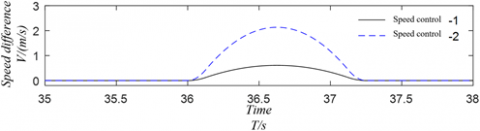
Assuming that the reel mechanism is not working and the hose length is 22m, the receiver was docked with two speed control methods at time T=35s. The control results are illustrated in Figure 3, and the changes in hose shape at two control modes are manifested in Figure 4, where Xn, Yw, and Zw are the distances of the current hose position relative to the x, y, and z axes, respectively. In addition, the changes in hose tension at two control modes are displayed in Figure 5. The simulation results indicate that the HWP is more obvious when the receiver is docked under the mode of speed control-2.
Figure 3. The control results
3.2.2 Reel control
The reel mechanism takes the tanker outlet tension as a feedback to control the pulling force on the hose within a certain range. Our simulation aims to disclose how the reel mechanism affects the hose state during the docking. The main technical parameters were configured as: the total mass M of the reel and hose, 68.08kg; the initial hose length L0: 14m; the controllable spring length L1: 3m; the binding force coefficient κ: 10,000N/m. To obtain more obvious control effect, the speed control-2 was adopted for the reel control simulation. The change in hose shape during docking is illustrated in Figure 6.
Figure 4. The changes in hose shape at two control modes
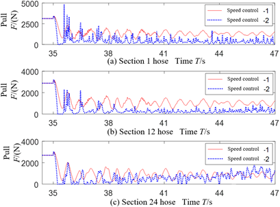
Figure 5. The changes in hose tension at two control modes
Figure 6. The change in hose shape during docking
3.2.3 Hose length
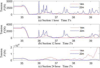
During the docking, the hose is fully towed. Hence, its dynamic performance hinges on its length. Suppose the reel mechanism is not working, the hose length is 14m, and the receiver is docked at speed control-2. Then, the changes in hose shape and hose tension are recorded in Figures 7 and 8, respectively.
Figure 7. The changes in hose shape at speed control-2
Figure 8. The changes in hose tension at speed control-2
3.3 Discussion
(1) Validation results on speed control
Figure 4 shows that, in speed control-1, the forward distance of the receiver and the forward movement of the cone sleeve became shorter, and the hose had a low degree of slackness, along with the slow and limited speed changes. On the contrary, in speed control-2, the hose shape changed significantly, along with the fast and significant speed changes. The contrast suggests that the speed should be controlled to smoothen the change and minimize the amplitude of hose shape, thereby reducing the HWP during the docking.
Figure 5 shows that the hose tension plunged during docking under the two speed control modes. After docking, the tension gradually increased along the hose. Comparatively, speed control-2 brought a larger changing amplitude than speed control-1. Under speed control-2, the tension was not restored for a long time, indicating that the hose is relaxed; the oscillation of the tension means the hose slightly flutters. At this time, a strong incoming airflow will blow the loose hose towards the cone sleeve, leading to HWP hazard and causing serious accidents (L-1, L-2, L-3).
The above results demonstrate the necessity of speed control (CA-1) during docking. In this phase, SC-6, SC-9, SC-10, and SC-12 must be observed to control the speed, and prevent excessive hose slack from forming HWP.
(2) Validation results on reel control
As shown in Figure 6, the hose could be rewound quickly, and the swing amplitude was clearly reduced under reel control. It can be concluded that the reel mechanism can significantly suppress the large swing of the hose and mitigate the HWP. Hence, it is highly necessary to check the reel mechanism, and maintain its ideal working condition (SC-34).
(3) Validation results on hose length
Comparing Figure 7 with Figure 4(b), it can be seen that the hose swing was intensified during docking, as the hose length was reduced to 14m. This is because a short hose has a light weight and stays close to the tanker vortex. Consequently, the hose is easily affected by the wake field, and thus shakes more vibrantly.
As shown in Figure 8, after the hose length was shortened from 22m to 14m, the hose tension of the 24th section was out of control 4s after docking, entering the state of fierce swing. This increases the probability of system-level losses (L-1, L-2, L-3). Therefore, properly increasing the hose length can effectively enhance the safety of aerial refueling (SC-32).
To sum up, the HWP of aerial refueling is mainly controlled by three factors: the docking speed, the hose tension controlled by the reel mechanism, and the hose length. The proposed SCs were proved effective and accurate through simulation validation.
This paper relies on the STPA to examine the failure modes and derive the solutions to the HWP in aerial refueling. Through the analysis, three control factors were identified for the HWP, namely, the docking speed, the hose tension controlled by the reel mechanism, and the hose length. The proposed SCs were verified through simulations based on each of the three control factors. The simulation results suggest that the HWP probability can be effectively reduced by proper setting of docking speed, effective reel control, and suitable design of hose length. The research findings make up for the gap of traditional safety analyses, and provide a good reference for the prevention of the HWP. Our analysis approach can serve as a risk assessment method for flight missions, facilitating the improvement of flight rules and enhancement of combat training of the air force. Of course, there are several limitations of this research: the STAMP theory lacks systematic quantitative analysis; the quantitative description of causal factors needs to be further improved. These two issues will be addressed in the future research.
Authors gratefully acknowledge the support of the National Nature Science Foundation of China (Grant No.: NSFC 71401174, 71501185) and the Aviation Science Foundation (Grant No.: ASF 20165196018).
[1] Maiersperger, W. (1954). General design aspects of flight refueling. Aeronautical Engineering Review, 13(3): 52-61.
[2] Cui, L.J., Zhang J.K., Ren, B., Chen, H.R. (2018). Research on a new aviation safety index and its solution under uncertainty conditions. Safety Science, 107: 55-61. https://doi.org/10.1016/j.ssci.2018.04.001
[3] Wang, X.F., Li, J.M., Kong, X.W., Dong, X.M., Zhang, B. (2019). Towards docking safety analysis for unmanned aerial vehicle probe-drogue autonomous aerial refueling based on docking success-probability and docking reachability. Proceedings of the Institution of Mechanical Engineers, 233(11): 69217617. https://doi.org/10.1177/0954410018806804
[4] Vassberg, J.C., Yeh, D.T., Blair, A.J., Evert, J.M. (2002). Dynamic characteristics of a KC-10 wing-pod refueling hose by numerical simulation. 20th AIAA Applied Aerodynamics Conference, St. Louls, Missouri. https://doi.org/10.2514/6.2002-2712
[5] Wang, H.T., Dong, X.M., Xue, J.P., Liu, J.L. (2014). Dynamic modeling of a hose-drogue aerial refueling system and integral sliding mode backstepping control for the hose whipping phenomenon. Chinese Journal of Aeronautics, 27(4): 930-946. http://dx.doi.org/10.1016/j.cja.2014.06.010
[6] He, Q., Wang, H., Chen, Y., Xu, M., Jin, W. (2017). Command filtered backstepping sliding mode control for the hose whipping phenomenon in aerial refueling. Aerospace Science and Technology, 67: 495-505. https://doi.org/10.1016/j.ast.2017.04.020
[7] Ahmad, M., Pontiggia, M. (2015). Modified swiss cheese model to analyse the accidents. Chemical Engineering Transactions, 43: 1237-1242. https://doi.org/10.3303/CET1543207
[8] Kamil, M.Z., Taleb-Berrouane, M., Khan, F., Ahmed, S. (2019). Dynamic domino effect risk assessment using Petri-nets. Process Safety and Environmental Protection, 124: 308-316. https://doi.org/10.1016/j.psep.2019.02.019
[9] Waterson, P., Jenkins, D.P., Salmon, P.M., Underwood, P. (2016). ‘Remixing Rasmussen’: The evolution of Accimaps within systemic accident analysis. Applied Ergonomics, 59: 483-503. https://doi.org/10.1016/j.apergo.2016.09.004
[10] Qiao, W.G., Li, X.C., Liu, Q.L. (2019). Systemic approaches to incident analysis in coal mines: Comparison of the STAMP, FRAM and “2–4” models. Resources Policy, 63: 101453. https://doi.org/10.1016/j.resourpol.2019.101453
[11] Leveson, N.G. (2004). A new accident model for engineering safer systems. Safety Science, 42(4): 237-270. https://doi.org/10.1016/S0925-7535(03)00047-X
[12] Jing, L.L., Bai, Q.G., Guo, W.Q., Feng, Y., Liu, L., Zhang Y.Y. (2020). Contributory factors interactions model: A new systems-based accident model. Systems Research and Actional Science, 37(2): 255-276. https://doi.org/10.1002/sres.2618
[13] Zhang, F., Xu, X., Cheng, L., Wang, L., Liu, Z., Zhang, L. (2019). Global moment‐independent sensitivity analysis of single-stage thermoelectric refrigeration system. International Journal of Energy Research, 43(15): 9055-9064. https://doi.org/10.1002/er.4811
[14] Zhang, F., Xu, X.Y., Cheng, L., Tan, S.W., Wang, W.H., Wu, M.Y. (2020). Mechanism reliability and sensitivity analysis method using truncated and correlated normal variables. Safety Science, 125: 104615. https://doi.org/10.1016/j.ssci.2020.104615
[15] Zeleskidis, A., Dokas, I.M., Papadopoulos, B. (2020). A novel real-time safety level calculation approach based on STPA. MATEC Web of Conferences, 314: 01001. https://doi.org/10.1051/matecconf/202031401001
[16] Yousefi, A., Hernandez, M.R. (2020). A novel methodology to measure safety level of a process plant using a system theory based method (STAMP). Process Safety and Environmental Protection, 136: 296-309. https://doi.org/10.1016/j.psep.2020.01.035
[17] Plioutsias, A., Karanikas, N. (2015). Using STPA in the evaluation of fighter pilots training programs. Procedia Engineering, 128: 25-34. https://doi.org/10.1016/j.proeng.2015.11.501
[18] Burns, R.S., Clark, C.S., Ewart, R. (2005). The automated aerial refueling simulation at the AVTAS laboratory. AIAA Modeling and Simulation Technologies Conference and Exhibit, San Francisco, Californla. https://doi.org/10.2514/6.2005-6008
[19] Cooper, J.R., Rothhaar, P.M. (2018). Dynamics and control of in-flight wing tip docking. Journal of Guidance, Control, and Dynamics, 41(11): 2327-2337. https://doi.org/10.2514/1.g003383
[20] Sun, B., Li, Y., Wang, Z.L., Li Z.F., Xia, Q., Ren, Y., Feng, Q., Yang, D.Z., Qian, C. (2020). Physics-of-failure and computer-aided simulation fusion approach with a software system for electronics reliability analysis. Eksploatacja i Niezawodnosc - Maintenance and Reliability, 22(2): 340-351. http://dx.doi.org/10.17531/ein.2020.2.17