Rekia Amieur | Abdelkader Djehiche![]() | Chaima Lalia Boumaàza | Mustafa Gafsi | Djemoui Lalmi*
| Chaima Lalia Boumaàza | Mustafa Gafsi | Djemoui Lalmi*![]()
© 2023 IIETA. This article is published by IIETA and is licensed under the CC BY 4.0 license (http://creativecommons.org/licenses/by/4.0/).
OPEN ACCESS
Embankment seepage occurs when water infiltrates through the soil or embankment body and flows along its path of least resistance. This can be detrimental to the stability of the embankment as it can lead to erosion, soil liquefaction, and ultimately, failure. The phenomenon of water infiltration is evolving and it can jeopardize the durability or stability of these structures and consequently the safety of the public. The research paper focuses on studying the seepage through a homogenous earth dam constructed on an impervious foundation using the numerical model SEEP/W. The main objective is to investigate the impact of the vertical drain's location on the stability and total seepage discharge across the dam's cross section. The model considers various scenarios involving different heights, positions, and upstream water heads for the vertical drain. The study findings suggest that the height of the drain has a more significant influence on the overall flow rate of infiltration compared to its position.
homogenous earth dams, seepage quantity, SEEP/W software, stability, vertical drain
Controlling seepage of water through pores and cracks in earth and rock formations is of utmost importance in various engineering applications, especially in the design and construction of earth dams. Uncontrolled seepage can have severe consequences, including economic losses and loss of lives. Therefore, it is crucial to implement measures to manage and control seepage effectively [1].
The statistical study mentioned indicates that a significant proportion (80%) of dam collapses can be attributed to water seepage through the body or foundation of the dam. This seepage occurs due to the differential head, which refers to the difference in water levels between the upstream and downstream sides of the dam [2].
Maintaining the phreatic surface inside the dam can be achieved through various means, including the implementation of an effective drainage system. This system helps intercept and collect seepage water, reducing the water pressure within the embankment and minimizing the potential for seepage-related problems [3]. To limit seepage and pore-water pressures and prevent the formation of a seepage face in embankments, several precautions can be taken during design and construction [4].
Kozeny's [5] studies contributed to the understanding of how the properties of the filter materials, such as permeability and porosity, affect the seepage flow through the dam. He developed equations and models to calculate the flow rates and hydraulic gradients based on the characteristics of the filter materials and the hydraulic conditions. The installation of internal drains involves careful design considerations, including the placement, spacing, and permeability of the drain materials. Proper planning ensures that the drains effectively intercept seepage water and channel it towards downstream collection points or external drainage systems [6]. The material properties of the drains are crucial for their performance. The graded sand and gravel mixture used in the drains should have high permeability to allow for efficient water flow. The gradation of the materials should be carefully selected to ensure uniformity and prevent clogging. Additionally, the compaction of the material during construction is important to maintain its permeability and prevent settlement [7]. Pore pressures within the dam's cross-section or in its foundation are also important to analyze. High pore pressures can lead to reduced shear strength of the soil, which can result in dam failure. By conducting a seepage analysis, the distribution of pore pressures can be estimated and measures can be taken to mitigate any potential issues [8].
The Laplace equation, which governs water seepage, is a second-order partial differential equation and is generally difficult to solve analytically. Analytical solutions are only possible for simple and special cases where the boundary conditions and the geometry of the problem are well-defined and have specific mathematical properties [9]. Researchers have indeed invoked empirical, graphical, and numerical methods to analyze water seepage in various geotechnical applications, including earthen dams [10, 11].
The image method, combined with the developed equation and the graphical representation, allowed Abd El Razek [12] to study and analyze the seepage characteristics of the earth dam with a chimney filter. This approach provides insights into the behavior of seepage flow, the effectiveness of the filter system, and the stability of the dam under various conditions. analytical methods have their limitations due to simplifying assumptions, numerical methods such as finite element, finite difference, and finite volume methods offer more flexibility and applicability for investigating seepage in porous environments. The choice of method depends on the specific problem and the level of complexity involved [13].
Analyzing seepage control methods involves evaluating the effectiveness of various techniques for reducing or preventing seepage in earth dams [14, 15] using analytical methods. Djehiche et al. [16, 17] using Experimental modeling to study seepage through earth dams by using seepage tanks and Experimental modeling using seepage tanks is another approach to study seepage through earth dams and Sachpazis [18] and Salem et al. [19] used a combination of analytical methods, numerical modeling, and experimental approaches to study the seepage introduce several boundary conditions on the passages to numerical simulation because numerical models take less time than the construction of experimental models.
Femmam and Benmebarek [20] used FLAC 2D and Géo-slope software for seepage analysis, including the evaluation of pore pressures and their impact on slope stability. Tung et al. [21] used a combination of FLAC 2D and SEEP/W allows for a comprehensive analysis of the stability and seepage behavior of an earth dam under rapid drawdown conditions. The analysis of seepage through earth dams under steady-state conditions using a two-dimensional finite element code is a common approach in geotechnical engineering research. This type of numerical analysis allows for estimating the seepage behavior and quantifying the flow of water through the dam [22]. Sazzad [23] has been investigated numerically and analytically with the use of finite element technique to study the seepage through earth dam, The study conducted by Shakir [24] focused on a zoned earth dam and utilized a finite element model to analyze the seepage quantity and the location of the free surface. The researchers investigated various scenarios by varying the permeability, thickness, and location of the dam's core.
El Molla [25] used the finite element numerical model, she simulated the behavior of the dam with and without the vertical sheet pile. she analyzed various factors, such as seepage flow patterns, seepage quantities, and changes in pore water pressure within the dam and by utilizing FEM, Fu and Sheng [26] were able to model the complex flow patterns and changes in seepage quantity that occur during unsteady conditions.
The experimental results obtained from SEEP/W were then compared with theoretical findings to validate their accuracy and reliability. By comparing the two sets of results, Jamel [27] were able to develop an empirical equation that could estimate the quantity of seepage in the homogenous earth dam. By using finite element software SEEP/W [28]; established steady and transient models, Numerical modeling of SLOPE/W and SEEP/W tools of GEOSTUDIO software [29] to analyze the factor of safety of slopes under steady state seepage and sudden drawdown conditions. These tools allow engineers to simulate the behavior of slopes and assess their stability.
After this literature the origin of this article is to study the impact of variations in geometrical and geotechnical parameters on the seepage quantity and slope stability of an earth dam with a chimney drain on an impervious foundation. The study utilizes the SEEP/W software to analyze seepage and the SLOPE/W software to assess slope stability.
In the present study, the focus is on a homogeneous earth dam constructed on an impervious foundation. The dam has a total height of 28 meters. We investigate the impact of different crest widths (bc)-specifically, 7m, 8m, 9m, and 10m-on the dam's behavior. The head acting on the upstream side of the dam (H) is set at 25 meters, while the downstream side is assumed to be dry. The study further explores the influence of varying the base width of the dam (B) and the slopes on both the upstream and downstream sides. Regarding the permeability of the dam material, a horizontal permeability value of 10-7m3/s is considered. Additionally, the ratio of horizontal to vertical permeability (Kh/kv) is set at 1.
This research aims to study the characteristics of seepage through homogeneous isotropic earth dams rested on an impervious base provided with drainage chimney systems. With different location.
In order to achieve the objectives of this study, Geostudio software is used. The Geostudio suite consists of various software products that utilize finite element code to analyze the performance of dams and levees. In this study, two specific software products from the Geostudio suite were utilized:
SLOPE/W: This software is used for slope stability analysis. It allows engineers to assess the factor of safety of slopes under different conditions, such as steady state seepage and sudden drawdown. SLOPE/W can help identify potential slope failures and design appropriate stabilization measures [30].
SEEP/W: SEEP/W is used for groundwater seepage analysis. It enables engineers to simulate and analyze the flow of water through porous media, such as dams and levees. SEEP/W can provide insights into seepage patterns, pore water pressures, and the overall behavior of the system [31].
The finite element method can be used to solve the two-dimensional seepage equations and obtain an accurate representation of the water flow behavior in the given domain equation can be derived as [30]:
$\int[\nabla(k \nabla h)-q] . \varphi d \Omega=0$ (1)
- $\nabla$ is the gradient operator,
- k is the hydraulic conductivity,
- h is the hydraulic head,
- q is the source/sink term,
- $\varphi$ is the weighting function,
- Ω is the domain of interest.
SEEP/W is a software program within the GeoStudio software collection that is specifically designed to analyze the steady-state phase of an earth dam. It utilizes partial differential equations to calculate and simulate the flow of water through the dam, allowing for the investigation of leakage and water flow patterns. By solving these equations, SEEP/W provides valuable insights into the behavior and stability of the dam under steady-state conditions. The equations to be the following:
$\frac{\partial}{\partial x}\left(k_x \frac{\partial H}{\partial x}\right)+\frac{\partial}{\partial x}\left(k_y \frac{\partial H}{\partial y}\right)=0$ (2)
where, - K is the hydraulic conductivity of the dam material - H is the piezometric head (water pressure) in the dam - x and y are the Cartesian coordinates.
After investigating the steady-state phase of the earth dam using Seep/w, the downstream slope stability of the dam can be assessed using another software program called Slope/w, which is also part of the GeoStudio software collection [23].
SLOPE/W software is used to assess the stability of slopes and analyze factors for upstream and downstream slope for different scenarios. The analysis is performed in terms of the drain location for various load conditions. We used slip surface: “Entry-exit”.
SLOPE/W utilizes Spencer's method to determine the factor of safety for both the upstream and downstream sides of an earthen dam. The factor of safety is a measure of the stability of the slope or dam and indicates how close it is to failure.
SEEP/W is a valuable tool for analyzing and designing solutions for groundwater flow and seepage-related problems in a wide range of geotechnical, civil, hydrogeological, and mining engineering projects the following tasks should be performed in sequence:
1. Geometry and Meshing;
2. Material Models and Properties;
3. Boundary Conditions;
4. Analysis Types;
5. Visualization of Results.
In GeoStudio, the View Results Information command allows users to access all output data for nodes and Gauss points anywhere in the model. This command provides a comprehensive view of the results obtained from the analysis [30].
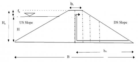
In the present study, a homogeneous earth dam is being considered, which is constructed on an impervious foundation. The dam has a total height of 28m. The study aims to investigate the effect of different crest widths (bc) on the dam's behavior. The considered crest widths are 7m, 8m, 9m, and 10m. The upstream side of the dam is subjected to a head (H) of 25m, while the downstream side remains dry. It is important to note that the base width of the dam, denoted as B, is being changed. In addition to changing the base width, the study also examines variations in the slopes of both the upstream and downstream sides of the dam. The horizontal permeability of the dam material is assumed to be 10-7m3/s. Furthermore, the hydraulic conductivity ratio, Kx/Ky, is considered to be equal to 1 (Figure 1).
Figure 1. General description of the variables involved in the Dam
K=hydraulic conductivity (m/sec); H=Height of the dam (m); Fb=Free board (m); bd=width between vertical drain and downstream(m); b=The width of the dam's crest (m).
To achieve numerical simulation of seepage through the earth dam and upstream slope stability there are a 2 analysis (Initial steady state-Stability). The first analysis of water transfers represents the equilibrium conditions within the embankment taking into account the presence of the reservoir and we change a height of drain. The first analysis of water transfers represents the equilibrium conditions within the embankment taking into account the presence of the reservoir and we change a height of drain. For this case study, 3 boundary conditions are defined:
-A potential infiltration face characterized by a zero total infiltration rate on the facing of the downstream slope.
-A maximum hydraulic load on the facing of the upstream slope of the reservoir simulating that the reservoir is full.
-The lowest point of the face of the upstream slope is subjected to zero pressure. - The calculation is done at steady state. The analysis of the stability of the slopes of this case transfer simulation makes it possible to determine the influence of this head change in the pore pressure conditions within the embankment on the safety factor.
The first model, (Figure 2) as described, is a homogeneous earth dam constructed on an impervious base, The specific parameters for this model are as follows: the width of the dam’s crest bc is 8m, the width of the dam at its base B is 134m, with a height of dam H=28m, an upstream slope n=2.5, a downstream slope m=2.0 and location of the vertical drain is bd=56m. The results of simulation as shown in Table 1.
Table 1. Results of infiltration flow simulation and safety coefficient (variable hd and constant bd)
|
Upstream Slope |
N=2.5 |
|
|
Hd (m) |
Q (m3/s) |
Fs |
|
10 |
2.47E-06 |
1.09 |
|
15 |
2.45E-06 |
1.09 |
|
20 |
2.36E-06 |
1.085 |
|
25 |
2.21E-06 |
1.072 |
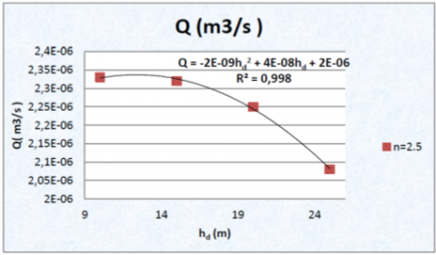
Figure 2. The impact of varying the vertical height of the drain on the total seepage
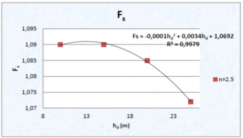
Figure 3. The impact of varying the vertical height of the drain on the safety coefficient
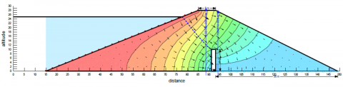
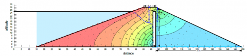
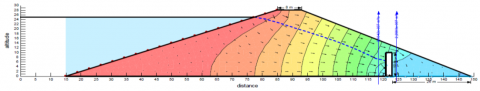
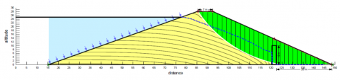
Figure 4. Infiltration simulation results, hd=10m
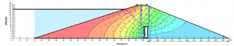
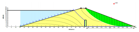
Figure 5. Infiltration simulation results, hd=25m
Figure 6. Stability simulation results, (hd=10m)
Figure 7. Stability simulation results, (hd=25m)
The flow net is plotted the total seepage discharge through the earth dam for height vertical drain as well their position.
Figure 2 illustrates that the total seepage discharge through the earth dam decreases with an increase in the height of the drain. This suggests that raising the height of the drain has a favorable impact on seepage control and can lead to a reduction in the overall seepage discharge from the dam.
Because with the increase in the height there is a decrease in the hydraulic gradient, therefore a decrease in speed, depending on the Darcy's law implies a decrease the total seepage discharge. The relationship between the height of the drain and the total seepage discharge can be explained by Darcy's theory and the principles of groundwater flow.
According to Darcy's law, the flow of water through a porous medium is directly proportional to the hydraulic gradient. As the percolation length increases (which can be achieved by raising the drain height), the average hydraulic gradient decreases. This means that the driving force for seepage flow decreases, leading to a reduction in the total seepage discharge. Additionally, as the height of the drain increases, the distance between the upper end of the drain and the phreatic line (the water table or the level at which the pressure is atmospheric) is reduced. This decrease in distance causes the flow lines in this area to converge, creating a convergent flow pattern. The converging flow lines add resistance to the flow, which reduces the total seepage discharge [8, 25]. It noticed that the safety coefficient is dependent on the height of the drain, the safety coefficient decreases with the increase in the height of the drain, but this decrease is very small, corresponds to a decrease in 1.7%. As shown in Figure 3, it can be concluded that the optimum height for stability and leakage rate, it is convenient to take the height of the drain (hd=0.54.H).
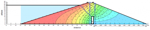
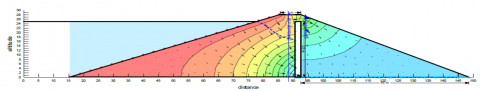
Figure 4 and Figure 5 show the flow net trough the dam for different heights of vertical drain considering dry downstream m=2.
Figure 6 and Figure 7 show the stability simulation results for different heights of vertical drain hd= 10m et hd=25m.
The second model of earth dam which is constructed on an impervious base, the dimensions of the dam are as follows:
The width of the dam’s crest bc=8m, the width of the dam at its base B is 134m, with a height H=28m, an upstream slope n=2.5, a downstream slope m=2.0 and the height of the vertical drain hd=10m. The following Table 2 represents the numerical results of the total leakage discharge and the safety coefficient for the different bases.
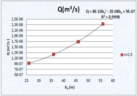
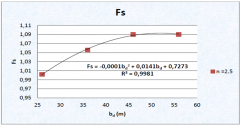
Figure 8 shows the relationship between the total seepage discharge (Q) and the location of the chimney drain within the dam. The chimney drain plays a crucial role in allowing excess water to drain out of the dam and helps in maintaining its stability and integrity. By analyzing the seepage discharge at different positions of the chimney drain, we can assess the effectiveness of the drainage system and make necessary adjustments to ensure the dam's safety.
Table 2. Results simulation of the total leakage discharge and the safety coefficient for (variable bd and constant hd)
|
Upstream Slope |
n=2.5 |
|
|
Bd(m) |
Q(m3/s) |
Fs |
|
26 |
9.18 E-07 |
1.002 |
|
36 |
1.24 E-06 |
1.056 |
|
46 |
1.69 E-06 |
1.09 |
|
56 |
2.33 E-06 |
1.09 |
Figure 8. Impact of varying the drain’s location on the total seepage
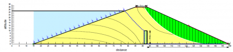
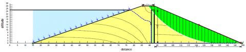
Figure 8 demonstrates that the total seepage discharge increases as the length of the horizontal drain increases.
Because with the increase in the length there is an increase in the hydraulic gradient (i=∆h/∆l where ∆h is constant and ∆l is variable), therefore increase in flow velocity, according to Darcy's law (v=Ki implies an increase in seepage flow Q=VS see Figures 9-13 below.
Figures 14-23 show the effect of vertical drain’s location bd on the safety coefficient and the saturation line and the sliding surface depending the relative length of the horizontal drain are respectively.
These results reveal that for the case of the dam with the mechanical characteristics c'=20KN/m2 and ϕ'=18° retained for the present numerical experiment, the safety coefficient of the slope Fs is of the order of 1.002. Although the dam is mechanically stable (Fs>1) compared with circular sliding, it is evident that increasing the length of the drain improves the safety factor compared to circular sliding. The safety factor is a measure of the stability of the dam, and a higher safety factor indicates a more stable condition. As the length of the drain increases, it enhances the drainage capacity, allowing for better dissipation of pore water pressures. This helps to reduce the risk of excess pore water pressures building up, which can lead to decreased stability and potential sliding; from this parametric study, it is practical to take a length of the drain bd include between $\left(\frac{B}{3.6}<b_d<\frac{B}{2.6}\right)$.
Figure 9. Flow net simulation result, bd=26m
Figure 10. Flow net simulation result, bd=56m
Figure 11. Location of the critical slip surface in dam with bd=26m
Figure12. Location of the critical slip surface in dam with bd=56m
Figure 13. Effect of drain’s location on safety coefficient
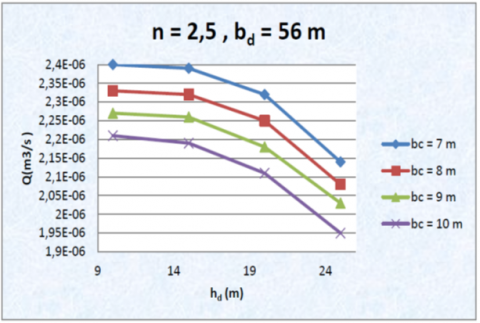
In the first we take four width crests (7, 8, 9, 10 m) and change the height of vertical drain; Table below show result of simulation (Table 3).
The figures below present the result simulation of seepage rate with crest width and drain’s heigh.
Table 3. Results of infiltration flow simulation and safety coefficient at different width of the crest of the earth dam for (variable hd and constant bd)
|
n=2. 5 bd=56m |
||||||||
|
bc |
7m |
8m |
9m |
10m |
||||
|
hd |
Q(m3/s) |
Fs |
Q(m3/s) |
Fs |
Q(m3/s) |
Fs |
Q(m3/s) |
Fs |
|
10 |
2.4 E-06 |
1.095 |
2.33 E-06 |
1.09 |
2.27 E-06 |
1.086 |
2.21 E-06 |
1.084 |
|
15 |
2.39 E-06 |
1.095 |
2.32 E-06 |
1.09 |
2.26 E-06 |
1.086 |
2.19 E-06 |
1.084 |
|
20 |
2.32 E-06 |
1.092 |
2.25 E-06 |
1.085 |
2.18 E-06 |
1.085 |
2.11 E-06 |
1.082 |
|
25 |
2.14 E-06 |
1.073 |
2.08 E-06 |
1.072 |
2.03 E-06 |
1.072 |
1.95 E-06 |
1.068 |
Figure 14. Flow net simulation results, hd=10m; bd=56m
Figure 15. Flow net simulation results, hd=25m; bd=56m
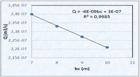
When the width of the crest increases, it leads to an increase in the flow length along the dam. As a result, the seepage flow has to pass through a longer path, which results in a higher pressure drop. The pressure drop is directly related to the seepage rate. Higher pressure drop means that there is a greater resistance to flow, and consequently, the seepage rate decreases.
In the second time we fixed the height of drain and change location of drain with same condition.
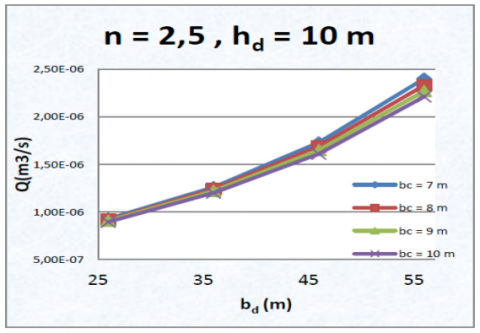
Figure 16. Effect the height’s drain and the width crests on the total seepage discharge (n=2.5 & bd=56m)
Figure 17. Impact of the width crests on the total seepage rate (n=2.5)
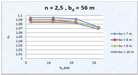
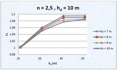
Figure 18. Variation of safety factor of the earth dam at different width of the crest and the drain’s height
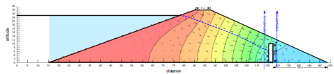
Figure 19. Flow net simulation results, hd=10m; bd=26m; bc=7m
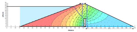
Figure 20. Flow net simulation results, hd=10m; bd=56m; bc=7m
Figure 21. Stability simulation results, hd=10m; bd=26m; bc=7m
Figure 22. Stability simulation results, hd=10m; bd=56m; bc=7m
Figure 23. Impact of width crest and drain’s location on seepage rate (hd=10)
Figure 24. Variation of safety factor of the earth dam at different width of the crest and the drain’s location hd=10
When the location of drain is in the middle of the dam, the total seepage flow through the dam increased, and we also notice when the width of the crest increases the infiltration rate is reduced, it can have a different effect on the infiltration rate. With a wider crest, there is an increase in the flow length along the dam cross section, which can result in a higher pressure drop and reduced infiltration rate.
The impact the drain’s location on the factor of safety in of the dam is shown in Figure 24. The value of the safety factor increases slightly when the drain is moved towards the center of the dam and decreases when the crest width is increased.
Another model is shown in Figure 25, Figure 26, it is a dam with same carcteristice but with different dimension, the width of the dam’s crest bc=8m, the width of the base B variable according to the downstream slope m, with a height H=28m, a slope upstream n=3.0, with a variable downstream slope (1.5, 2.0, 2.5 and 3.0) and the height of the vertical drain hd=25m. Table 4 presents the result simulation of seepage rate and the safety factor for different downstream (n= 3,2.5,2,1.5).
Table 4. The difference in seepage flow and the safety factor at different downstream slope of the earth dam
|
bc=8m hd=25m bd=56m n=3 |
|||
|
The base B |
Slope down Stream |
Q(m3/s) |
Fs |
|
176 |
3 |
2.07 E-06 |
1.613 |
|
162 |
2.5 |
2.06 E-06 |
1.344 |
|
148 |
2 |
2.05 E-06 |
1.093 |
|
134 |
1.5 |
2.03 E-06 |
0.899 |
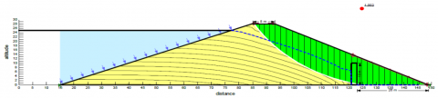
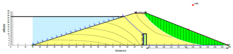
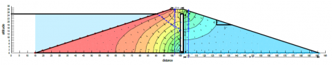
Figure 25. Infiltration simulation results, hd=25m; bc=8m, m=3.0
Figure 26. Stability simulation results, hd=25m; bc=8m, m=3.0
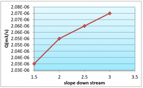
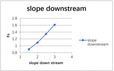
The Figures 27, 28 below shows the seepage rate Q through the homogeneous dam as a function of the downstream slope.
Figure 27. Effect of slope downstream on seepage rate
Figure 28. Effect of slope downstream on safety factor
It noticed that the seepage rate Q and the downstream slope safety coefficient Fs increase with the increase in the downstream slope. The location of the vertical drain slightly influences the value of the seepage discharge and the safety factor through the cross section of the dam. These results show the importance of the downstream slope on the stability in the earth dams.
The last model that we present here is a homogeneous earth dam with impervious base, the width of the dam’s crest bc is 8m, the width of the dam’s base B variable according to the downstream slope m, with a height H=28m, an upstream slope n=3.0, a variable downstream slope (1.5, 2.0, 2.5 and 3.0) and the height of the vertical drain hd=25m, with bd (variable).
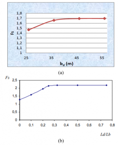
Figure 29. (a) Effect the drain position on the safety coefficient; (b) [10]
By comparing between the Figure 29 (a) and (b), we notice that the results are almost identical following the same gaits, that increasing the length of the drainage (vertical drain) leads to an increase in the stability of the dam. This is because a longer drain provides a larger area for water to flow out, reducing the water pressure within the dam and improving its stability. Numerical experimentation shows that the safety coefficient at a certain distance becomes independent of the position of the chimney.
We noticed that increasing both the upstream and downstream slopes of a homogenous earth dam leads to an increase in the seepage quantity or flow. However, the influence of varying the downstream slope has a greater impact on the seepage flow compared to the upstream slope. This implies that changes in the downstream slope have a more significant effect on altering the seepage characteristics of the dam. Additionally, the seepage quantity increases with increasing the height of upstream water depth and the length of the horizontal drain (L).
The safety coefficient is dependent on the height of the drain, the safety coefficient decreases with the increase in the height of the drain, but this decrease is very small, corresponds to a decrease in 1.7%. the vertical drain location has a minor influence on the value of the seepage flow rate and the maximum velocity through the cross section of the dam. The seepage rate decreases slightly as the drain is moved downstream. It was concluded that the optimum height for the stability and the leakage rate, it is convenient to take the height of the drain (hd=0.54H), and to take the drain’s length bd between $\left(\frac{b d}{3.6}<b_d<\frac{b d}{2.9}\right)$.
We presented the results of numerical experimentation for a fixed upstream slope dam for different crest widths and different vertical drain positions, it was concluded that the water heigh is generated the drainage flow, the slope downstream, the size of the drain and the width of the crest. And to have a stable dam, you have to take the downstream slope (m≥2).
At the end we recommended it is necessary to choose the length, the position of the drain and the optimal downstream slope to have an economical dam, and at the same time increase their stability and limit the leakage rate.
|
A |
A designation for summation over the area of an element |
|
B |
Crest width of the dam (m) |
|
Bd |
Width between vertical drain and downstream (m) |
|
c’ |
Cohesion |
|
I |
The gradient of total hydraulic head |
|
Fb |
Free board (m) |
|
Fs |
The safety coefficient |
|
H |
Height of the dam (m) |
|
K |
Permeability of dam soil (m/sec) |
|
L |
designation for summation over the edge of an element |
|
M |
Downstream slope |
|
N |
Upstream slope |
|
Q |
The source/sink term |
|
Q |
The total seepage discharge m-3/s |
|
T |
Time |
|
V |
The Darcian velocity |
|
$\varphi$ |
The weighting function |
|
Ω |
The domain of interest |
|
ϕ' |
Friction angle |
|
$\nabla$ |
The gradient operator |
[1] Creager, W.P., Barbour, F.A. (1939). Design and maintenance of earth dams with discussion. Journal American Water Works Association, 31(8): 1335-1360. https://www.jstor.org/stable/41232290.
[2] Modi, P.N. (2011). Irrigation Ressources En Eau et génie de l'énergie Hydraulique. Standard Book House, Delhi.
[3] Stephens, T. (2010). Manual on small earth dams. Food and Agriculture Organization of the United Nations, Rome.
[4] Freeze, R.A. (1971). Influence of the unsaturated flow domain on seepage through earth dams. Water Resources Research, 7(4): 929-941. https://doi.org/10.1029/WR007i004p00929
[5] Kozeny, J. (1931). Grundwasserbewegung bei freiem spiegel, fluss und kanalversickerung. Wasserkraft und Wasserwirtschaft, 26(3): 28.
[6] Soleimani, S., Asakereh, A. (2014). Evaluation of static stability of earth dams using geostudio software case study: Nian dam, Iran. Annals of the Faculty of Engineering Hunedoara, 12(3): 265.
[7] Calamak, M., Yilmaz, A.N., Yanmaz, A.M. (2018). Performance evaluation of internal drains of earthen dams. Journal of Performance of Constructed Facilities, 32(6): 04018085. https://doi.org/10.1061/(ASCE)CF.1943-5509.0001232
[8] Ps, M.A., Balan, T.A. (2014). Numerical analysis of seepage in embankment dams. IOSR Journal of Mechanical and Civil Engineering IOSR-JMCE, ICICE, 4: 13-23.
[9] Cedergren, H.R. (1997). Seepage, Drainage, and Flow Nets. John Wiley & Sons.
[10] Abd El Razek, M., Nasr, R.I. (1994). Height of the horizontal filter in earth dams based on an impervious base. Journal of Alexandria Engineering, 33(3).
[11] Nasim, S. (2007). Seepage analysis of earth dams by finite elements. Doctoral dissertation, M. Sc. Thesis, Collage of Engineering, University of Kufa, Iraq.
[12] Abd El Razek, M. (1986-1987). Seepage characteristic of earth dams with an "L" shape filter. Bulletin of the Faculty of Engineering, Alexandria University, XXVI.
[13] Fakhari, A., Ghanbari, A. (2013). A simple method for calculating the seepage from earth dams with clay core. Journal of GeoEngineering, 8(1): 27-32. http://dx.doi.org/10.6310/jog.2013.8(1).4
[14] Rezk, M.A.E.R.M., Senoon, A.E.A.A.A. (2011). Analytical solution of seepage through earth dam with an internal core. Alexandria Engineering Journal, 50(1): 111-115. https://doi.org/10.1016/j.aej.2010.10.001
[15] Rezk, M.A.E.R.M., Senoon, A.A.A. (2012). Analytical solution of earth dam with upstream blanket. Alexandria Engineering Journal, 51(1): 45-51. https://doi.org/10.1016/j.aej.2012.01.004
[16] Djehiche, A., Amieur, R., Gafsi, M. (2014). The seepage throughthe earth dams with a vertical drain: An experimental study. Journal of Environmental Research and Development, 8(3): 471.
[17] Djehiche, A., Amieur, R., Gafsi, M. (2012). Seepage through earth dams with chimney drain on pervious foundation. Advanced Materials Research, 452: 538-542. https://doi.org/10.4028/www.scientific.net/AMR.452-453.538
[18] Sachpazis, C.I. (2014). Experimental conceptualisation of the flow net system construction inside the body of homogeneous earth embankment dams. Electronic Journal of Geotechnical Engineering, 19: 2114-2136.
[19] Salem, M.N., Eldeeb, H.M., Nofal, S.A. (2019). Analysis of seepage through earth dams with internal core. International Journal of Engineering Research & Technology (IJERT), 8(8): 768-77. https://doi.org/10.17577/IJERTV8IS080168
[20] Femmam, H., Benmebarek, N. (2014). Effets des drains sur la stabilite des barrages en terre. http://dspace.univ-tiaret.dz/handle/123456789/4873.
[21] Tung, S., Bhandari, G.N., Mukherjee, S.P. (2015). Effect of seepage cut-off below earthen dam under rapid drawdown. In 50th Indian geotechnical conference, Pune, India.
[22] Giglou, A.N., Zeraatparvar, A. (2012). Seepage estimation through earth dams. Journal of Basic and Applied Scientific Research, 2(8): 7861-7865.
[23] Sazzad, M.M., Roy, M.R.I.N.M.O.Y., Rahman, M.M. (2015). FEM based seepage analysis through earth dam. International Journal of Advances in Structural and Geotechnical Engineering, 4(3): 158-164.
[24] Shakir, R.R. (2011). Effect of an impervious core constructed into a large earth dam on the quantity of seepage. Thi-Qar University Journal of Engineering Science, 2(2): 1.
[25] El Molla, D.A. (2019). Seepage through homogeneous earth dams provided with a vertical sheet pile and formed on impervious foundation. Ain Shams Engineering Journal, 10(3): 529-539. https://doi.org/10.1016/j.asej.2018.12.008
[26] Fu, J.F., Sheng, J.I.N. (2009). A study on unsteady seepage flow through dam. Journal of Hydrodynamics, 21(4): 499-504. https://doi.org/10.1016/S1001-6058(08)60176-6
[27] Jamel, A.A. (2016). Analysis and estimation of seepage through homogenous earth dam without filter. Diyala Journal of Engineering Sciences, 9(2): 38-49. http://dx.doi.org/10.24237/djes.2016.09207
[28] Li, Q., Liu, J. (2010). Numerical analysis of the seepage field in core-dam. School of Civil Engineering and Architecture, Southwest Petroleum University, Chengdu, China, 610500: 492-499.
[29] Devi, D.D.L., Anbalagan, R. (2017). Study on slope stability of earthen dams by using GeoStudio software. International Journal of Advance Research, Ideas and Innovations in Technology, 3(6): 408-414.
[30] Seepage Modeling with SEEP/W. (2012). Seepage modeling with SEEP/W an engineering methodology. Edition GEO-SLOPE International LTD.
[31] Irzooki, R.H. (2016). Computation of seepage through homogenous earth dams with horizontal toe drain. Engineering and Technology Journal, 34(3): 430-440. https://doi.org/10.30684/etj.34.3A.1