MMarwa Foad Manher![]() | Hussam Ali Mohammed
| Hussam Ali Mohammed![]() | Hussein Abad Gazi Jaaz
| Hussein Abad Gazi Jaaz![]() | Ali Fadhil Naser*
| Ali Fadhil Naser*![]() | Ayad Ali Mohammed
| Ayad Ali Mohammed![]()
© 2023 IIETA. This article is published by IIETA and is licensed under the CC BY 4.0 license (http://creativecommons.org/licenses/by/4.0/).
OPEN ACCESS
The aim of this study is to evaluate the structural performance of digester tanks structure in Al-Jazeera sewage treatment plant within Dhi Qar province in the south of Iraq by adopting the experimental field tests and finite element analysis. Due to the significance of anaerobic digester structure, it is necessary to evaluate structural performance on a regular basis using damage inspection techniques and non-destructive tests, depending on the construction materials used to construct the structure of the digester tanks. The surface of the reinforced concrete walls of the digester tanks had numerous small cracks, and some compressive strength readings were lower than the design value, showing that there was a reduction in the safety factor of the structure, necessitating the application of modified action to enhance the structural performance of the digester tanks structures rather than the project's designer providing more safety factor. To increase the safety factor and structural performance of digester tanks, this study recommends utilizing a strengthening strategy that comprises building an additional reinforced concrete circle ring on the external walls of tanks in the top, middle, and bottom locations.
evaluate, digester tanks, compressive strength, stress, inspection, finite element method
There are higher than 90 percent of the sewage in the developing and underdeveloped countries is discharged unprocessed in the environmental areas because of absence of appropriate wastewater assemblage and treatment plants structures. The amount and strength of wastewater are administered by the proportions and socioeconomic situation of the people percent of the living area [1, 2].
Sewage is the wastewater which produced by a public. It is consisted of the combination of local wastewater, industrial wastewater, and rain water, where a single culvert system is existent for wastewater and rainstorm water. The components of sewage differ importantly and its description is significant for designing and calculating the dimensions of wastewater treatment plant buildings [1, 3, 4].
The structure of wastewater treatment plants ingests great quantities of energy. This energy is commonly obtained from the network. Through the previous years, there are several continuing methods have been adopted to evaluate the conceivable answers for both decreasing the energy ingesting and cumulative the renewable energy creation in the wastewater treatment plants buildings. In general, wastewater treatment plant is a structure includes different processes such as physical, chemical and biological which they are used to remedy wastewater and eradicate pollution. Practically, there are two or more steps of building in the design of wastewater treatment plant structure, depending on the capacity of the plant structure which is linked essentially to the amount of sewage which is determined for the people percent that living in the city. The expedition for cleanser energy sources and renewable energy has developed a motivation force in the present energy advertises. The creation of biogas through the anaerobic digestion of organic wastes offers another for energy source, recapture and waste handling [5-7].
A digester is a structure which has different forms according to use for. Also, it can be known as a tank. For circular form, the dimensions include diameter and height, and for rectangular form, the dimensions include width, length, and height. A digester can be constructed by using reinforced concrete or steel. The volume of domestic digester for only family is less than one cubic meter, but for industrial digester, the volume is more than 5,000 cubic meters. Anaerobic digestion uses the procedure of fermentation to discontinuity biological trouble from animals, plants or sewage to create biogas. This method occurs within a central scheme in a structure which known as an anaerobic digester. Also, this structure can be called as a bio digester. A complete mixture digester is essentially a tank wherein wastewater is mixed with an active mass of microorganisms. Usual erection of complete mixture systems consist of reinforced concrete tanks in or on wall and in floor heating [8, 9].
Completely blended digesters are best frequently applied to sewage sludge, actuated sludge, and compost digestion. They are represented the best generally functional conformation for anaerobic digestion. Digesters activate as completely blended containers, with one or the other gas recirculation or mechanical or liquid blending systems. The shapes of digesters can as cylinder-shaped and egg-shaped. Higher loading rate is severely count on attainable solid levels. The performance can frequently be improved by pre-absorbed solids. Digester is designed to operate at varies objective temperature varieties. The temperature varieties are normally between 86℉ and 100℉ according to mesophillic and between122℉ and 140℉ according to thermophilic [10, 11].
Normally, digesters structure can be categorized for two kinds. These kinds are wet digesters and dry digesters. So, wet digesters can be categorized into three kinds. The first kinds is conventional digesters, the second kinds is sludge retention digesters, and the third kinds is fixed films digesters. Dry digesters consist of three kinds of digesters which are continuous dry digesters, batch dry digesters, and large-scale dry digestion [11, 12].
An important Anaerobic Digester plant insurer claims that anaerobic digestion facilities may face major loss occurrences due to damage to operating equipment, structural collapse, fire, flood, or theft while they are in operation. These occurrences can frequently lead to protracted periods of process interruption, which can result in a loss of income, cleanup expenses, a danger of local pollution, and a reduction in local community confidence and support for the project, which can be challenging to regain. All plant operators and those responsible for its maintenance must have a thorough understanding of the dangers associated with an Anaerobic Digester plant, as well as the rationale behind the inclusion of these safety and control mechanisms. They must understand the repercussions of malfunctioning safety features, improper plant operation, and disregard for established protocols. Many large loss or damage occurrences are typically caused by human mistake [13].
There was no natural disaster to cause the shell to collapse. It is thought that a malfunctioning valve caused a high internal pressure to build up on the day of the collapse, allowing a considerable amount of sewage to be discharged inside the tank and filling the whole structure. As noted in the texts [14-18], and others, the collapse of reinforced concrete shells has been observed in a number of incidents. Ballesteros [18], for instance, reported the collapse of an elliptical paraboloidal shell while removing the formwork; the structure had obvious geometric flaws and construction flaws. Despite the fact that many instances of reinforced concrete tanks (or similarly shaped structures) failing owing to structural or construction issues are not documented in the open literature, this lack of publication does not aid other researchers in learning from failures [14-18].
A variety of internal and external parameters, including substrate, temperature, pH, HRT, slurry mixing, and C/N ratio, affect how well an anaerobic digester performance. In terms of the total amount of power used by the biogas plant and the rate at which biogas is produced, mixing is one of the most important elements that affects the efficiency of the biogas plant. There are several ways to mix in an anaerobic digester, including slurry recirculation, impeller mixing, and biogas recirculation [19-21].
According to importance of anaerobic digester structure, structural performance must be evaluated periodically by adopting damage inspection methods with non-destructive tests depending on the construction materials which used in the building of digester tanks structure. Therefore, the objective of this study is to evaluate the structural performance of digester tanks structure in Al-Jazeera sewage treatment plant within Dhi Qar province in the south of Iraq by application of the experimental and theoretical analysis.
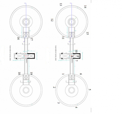
Al-Jazeera sewage treatment plant is located in Al-Nasiriya City within Dhi Qar province in the south of Iraq. The first stage of plant was constructed in 2012. The project was stopped between 2012 and 2021. The government decided to continues the construction works in this project in 2021. Therefore, there are needs to evaluate the structural performance of reinforced concrete digester tanks structures to establish the compressive strength of concrete and compare it with design values. There are two digester tanks which have 13.6m height and 15m diameter. The thickness of reinforced concrete wall of digester tanks is equal to 0.70m. Figure 1 shows the structure of digester tanks.
Figure 1. The structure of digester tanks
Damages investigation of concrete structures and bridge components are conducted to determine whether a structure is safe, to spot any areas that require maintenance, repair, or strengthening, to serve as a planning tool for funding those areas, and to inform designers and construction engineers of those areas that require attention. In general, damages field investigation of the concrete structure's goals include assessing structural performance, locating actual and potential sources of damage as soon as possible, explaining to the member state whether the area is safe or unsafe, identifying any maintenance, repair, and strengthening that needs to be done, and classifying the damaged parts of the bridge members [22-28].
The team of inspection visited Al-Jazeera sewage treatment plant and inspected the structure of digester tanks by using visual inspection process. They found that the appearance of structures is acceptable despite of there are many thin cracks (very low width). There are no any structural cracks penetrating the reinforced concrete walls of digester tanks. Therefore, some non-destructive tests are needed to evaluate the compressive strength of concrete to ensure that it conforms to the standard specifications, taking into account the time period for construction.
Engineers use non-destructive testing (NDT) as a method to find flaws in materials and structures, either during production or use. Ultrasonic, radiography, magnetic particles, eddy current, dye penetrant, and visual methods are frequently employed. Applying these tried-and-true methods and techniques to the entire spectrum of engineered structures is what this significant and expanding sector does [29].
In this study, Ultrasonic plus velocity test and Schmidt Hummer test were used to measure the compressive strength of concrete, then determining the reduction percentage of compressive strength of concrete according to construction value and design value.
4.1 Ultrasonic pulse velocity test
For more than 60 years, the ultrasonic pulse velocity method has been used to assess the quality of concrete. This technique can be used to find interior cracks and other faults in concrete as well as changes caused by freezing and thawing and harsh chemical environments. It is also possible to assess the strength of concrete test specimens and in-place concrete by employing the pulse velocity approach. Sending an ultrasonic wave pulse through concrete and measuring the time it takes for the wave pulse to go through the concrete are the two key components of ultrasonic pulse velocity measurement. A transmitter transducer and a receiver transducer both produce the ultrasonic pulse wave [30, 31]. Table 1 lists the velocity criterion for concrete quality grading [32].
Table 1. Velocity criterion for concrete quality grading [32]
|
UPV Pulsing (km/s) |
Excellent |
|
Above 4.5 |
|
|
3.5-4.5 |
Good |
|
3-3.5 |
Medium |
|
Below 3 |
Poor |
Because of the presence of many thin cracks on the surface of the reinforced concrete digestion tanks walls, which causes the dispersal of the waves emitted by the ultrasonic pulse velocity and gives wrong readings. Therefore, the team of investigation decided to adopt a Schmidt Hammer to evaluate the reinforced concrete walls.
4.2 Schmidt hammer test
The Schmidt hammer hardness test, which was initially created in 1948 for a rapid measurement of UCS but later expanded to assess the hardness and strength of rock, is an easy and non-destructive test. The working principle is straightforward: a spring releases a hammer, which indirectly strikes a rock surface via a plunger. The hammer's rebound distance, which ranges from 10 to 100, is then immediately read from the scale or electronic display. In other words, the rebound hardness is determined by the distance the hammer mass travels after striking a rock through a plunger and under the pull of a spring. Naturally, rebound distances increase with surface hardness. The rebound hammer method could be used to evaluate the uniformity of the concrete, the quality of the concrete in relation to the standard requirements, and the quality of one element of concrete in relation to another. It could also be used to evaluate the compressive strength of concrete with the aid of suitable co-relations between rebound index and compressive strength [33, 34].
In this study, 19 points were selected to apply the techniques of Schmidt hammer test. Each point has 16 readings of compressive strength, after that will take the average for all points. The distribution of tested point was selected for three locations. The first location contains points 1, 2, 3, 4, 5, and 6 on the middle height of tank No.1 and points 18 and 19 on the top height of tank No.1. The second location on the tank No. 2 which contains points 11, 12, 13, 14, and 15 on the middle height of tank No.2, and points 16 and 17 within top height of tank No.2. The third location was selected in the middle structure between two tanks which contains points 7, 8, 9, and 10. Figure 2 shows the location of tested points for two tanks.
(a)
(b)
Figure 2. Location of tested points for two tanks
The results of Schmidt hammer test can be seen that in Tables 2, 3, and 4. From these tables it can be shown that the average value of compressive strength of reinforced concrete wall for digester tank No.1 is equal to 31Mpa, the average value of compressive strength of reinforced concrete wall for digester tank No.2 is equal to 26Mpa, and 52Mpa for middle structure reinforced concrete wall. When comparing between the tested values with design compressive strength of concrete which is equal to 30MPa, the values of digester tank No.1 and middle structure are more than the design value. Whereas, the value of digester tank No.2 is lower than design value. According to above results and inspection process, there are many thin cracks on the surface of reinforced concrete walls of digester tanks and some compressive strength reading lower than design value, indicating that there is reduction in the safety factor of structure which needs to apply some modified action to improve the structural performance of digester tanks structures, instead of the designer of this project give more safety factor. Therefore, there is need to analyze tank structure by using Finite Element software to check the structural performance of digester tanks.
Table 2. Compressive strength for tank No. 1
|
Point |
1 |
2 |
3 |
4 |
5 |
6 |
18 |
19 |
|
Reading |
||||||||
|
1 |
34 |
34 |
28 |
0 |
32 |
32 |
40 |
48 |
|
2 |
32 |
32 |
28 |
0 |
36 |
34 |
44 |
40 |
|
3 |
36 |
32 |
28 |
0 |
32 |
36 |
36 |
40 |
|
4 |
36 |
36 |
28 |
0 |
34 |
36 |
36 |
46 |
|
5 |
36 |
30 |
28 |
0 |
34 |
32 |
40 |
44 |
|
6 |
36 |
32 |
26 |
0 |
32 |
36 |
40 |
44 |
|
7 |
34 |
34 |
26 |
0 |
32 |
40 |
44 |
50 |
|
8 |
36 |
36 |
28 |
0 |
30 |
36 |
40 |
46 |
|
9 |
34 |
32 |
26 |
0 |
30 |
32 |
44 |
44 |
|
10 |
34 |
32 |
26 |
0 |
30 |
34 |
44 |
40 |
|
11 |
36 |
32 |
28 |
0 |
30 |
30 |
38 |
46 |
|
12 |
34 |
32 |
28 |
0 |
28 |
38 |
44 |
44 |
|
13 |
36 |
34 |
28 |
0 |
28 |
36 |
48 |
46 |
|
14 |
36 |
32 |
28 |
0 |
36 |
34 |
48 |
46 |
|
15 |
38 |
32 |
30 |
0 |
30 |
36 |
48 |
44 |
|
16 |
40 |
30 |
30 |
0 |
32 |
36 |
42 |
38 |
|
Average |
36 |
33 |
28 |
0 |
32 |
35 |
42 |
44 |
|
Compressive strength (MPa) |
33.6 |
28.2 |
20.3 |
0 |
26.5 |
31.8 |
45.9 |
50.4 |
|
Compressive strength after corrected (MPa) |
34 |
28 |
20 |
Neg. |
27 |
32 |
40 |
40 |
|
Average |
31 |
|||||||
Table 3. Compressive strength for tank No. 2
|
Point |
11 |
12 |
13 |
14 |
15 |
16 |
17 |
|
Reading |
|||||||
|
1 |
28 |
26 |
20 |
28 |
28 |
36 |
36 |
|
2 |
28 |
28 |
32 |
32 |
34 |
36 |
30 |
|
3 |
28 |
28 |
32 |
28 |
44 |
36 |
36 |
|
4 |
28 |
30 |
30 |
28 |
36 |
36 |
30 |
|
5 |
28 |
28 |
34 |
28 |
34 |
34 |
36 |
|
6 |
28 |
30 |
34 |
28 |
34 |
36 |
34 |
|
7 |
28 |
26 |
34 |
28 |
38 |
30 |
32 |
|
8 |
28 |
26 |
34 |
30 |
35 |
36 |
32 |
|
9 |
30 |
30 |
28 |
30 |
34 |
36 |
30 |
|
10 |
30 |
26 |
34 |
32 |
32 |
36 |
32 |
|
11 |
30 |
30 |
34 |
30 |
34 |
38 |
34 |
|
12 |
30 |
28 |
30 |
36 |
38 |
38 |
30 |
|
13 |
30 |
28 |
30 |
35 |
34 |
38 |
32 |
|
14 |
30 |
26 |
36 |
30 |
30 |
38 |
36 |
|
15 |
30 |
30 |
30 |
32 |
36 |
38 |
34 |
|
16 |
32 |
26 |
34 |
28 |
38 |
38 |
30 |
|
Average |
29 |
28 |
31 |
30 |
35 |
36 |
33 |
|
Compressive strength |
21.8 |
20.3 |
24.9 |
23.3 |
31.8 |
33.6 |
28.2 |
|
Compressive strength after corrected (MPa) |
22 |
20 |
25 |
23 |
32 |
34 |
28 |
|
Average |
26 |
||||||
Table 4. Compressive strength for middle structure
|
Point |
7 |
8 |
9 |
10 |
|
Reading |
||||
|
1 |
44 |
44 |
50 |
42 |
|
2 |
42 |
42 |
48 |
38 |
|
3 |
50 |
42 |
44 |
46 |
|
4 |
46 |
38 |
44 |
42 |
|
5 |
42 |
38 |
50 |
40 |
|
6 |
48 |
42 |
44 |
48 |
|
7 |
54 |
38 |
44 |
42 |
|
8 |
50 |
42 |
46 |
44 |
|
9 |
50 |
40 |
46 |
44 |
|
10 |
50 |
40 |
42 |
50 |
|
11 |
46 |
44 |
48 |
40 |
|
12 |
46 |
44 |
46 |
46 |
|
13 |
46 |
38 |
46 |
42 |
|
14 |
54 |
42 |
46 |
42 |
|
15 |
54 |
38 |
48 |
48 |
|
16 |
50 |
38 |
50 |
48 |
|
Average |
48 |
41 |
46 |
44 |
|
Compressive strength |
60 |
43.7 |
55 |
50.4 |
|
Compressive strength after corrected (MPa) |
60 |
44 |
55 |
50 |
|
Average |
52 |
|||
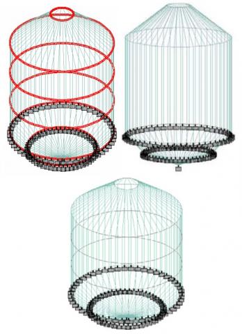
Digester tank are analyzed to study the distribution of loads and stresses and check the safety of structure according to standards. STAAD Pro software was used in the analysis process. Figure 3 shows the three dimensions model of digester tank. Figure 4 shows boundary condition of digester tank model.
Figure 3. Three dimensions model of digester tank
Figure 4. Boundary condition of digester tank model
5.1 Distribution of loads on the digester tank
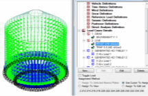
According to ACI code, Figure 5, Figure 6, and Figure 7 show the load cases details on the digester tank.
Figure 5. The all load cases details
Figure 6. The PRGY of live load
Figure 7. The TRP X0 of live load
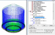
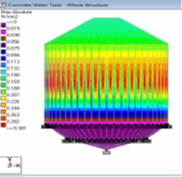
5.2 Analysis results of maximum absolute stresses distribution overall tank
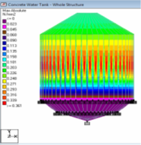
Figure 8 gives the results of dead load stresses with their distribution on the overall tank. From this figure it can be seen that the minimum value of stress is 0.019MPa which was located within bottom of digester tank and the maximum value of stresses due to dead load is equal to 0.301MPa. For live load, the values of stresses can be seen in Figure 9. The lower value is equal to 0.042 which is positioned within the lower quarter of digester tank and the higher value is located in the top of digester tank which is equal to 0.674MPa. All these values are within allowable design values of stresses.
Figure 10 shows the distribution of stresses due to dead load (1.4 load1). It can be shown that the maximum value of stresses of case 1 is equal to 0.421MPa within middle of tank. Figure 11 gives the values of stresses within overall tank due to dead and live loads (1.2 load 1 and 1.6 load 2). From this figure it can be noted that the value of maximum stress of case 2 increases comparing with case 1 which is equal to 1.14MPa. The case 3 includes the distribution of stresses according to (1.2 load 1and 1 load 2) which is shown in Figure 12. The higher value is equal to 0.732MPa in the top of tank. Figure 13 shows the case 4 which contains on the stresses due to (1.2 load 1) and the maximum value of stress is 0.360MPa within middle of tank. Figure 14 shows the distribution of stresses for case 5 which is (0.9 load 1). The maximum value is 0.271MPa. According to previous results, all values within allowable design values.
Figure 8. Results of maximum absolute dead load stresses with their distribution on the overall tank
Figure 9. Results of maximum absolute live load stresses with their distribution on the overall tank
Figure 10. Distributions of maximum absolute stresses due to dead load (1.4 load1) for case 1
Figure 11. Distributions of maximum absolute stresses due to dead and live loads (1.2 load 1 and 1.6 load 2) for case 2
Figure 12. Distributions of maximum absolute stresses due to dead and live loads (1.2 load 1 and 1 load 2) for case 3
Figure 13. Distributions of maximum absolute stresses due to dead load (1.2 load 1) for case 4
Figure 14. Distributions of maximum absolute stresses due to dead load (0.9 load 1) for case 5
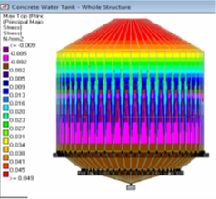
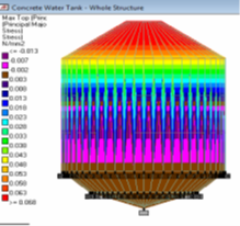
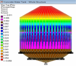
5.3 Analysis results of maximum top principal major stress distribution overall tank
The stresses analysis of tank top due to dead and live load can be seen that in Figure 15 and Figure 16. From these Figures, the higher value of stress due to dead and live loads in the tank top is 0.049MPa and 0.674MPa respectively. For load cases 1 to 5, Figure 17, Figure 18, Figure 19, Figure 20, and Figure 21 show the values of maximum principal major stress which is equal to 0.068MPa, 1.14MPa, 0.732MPa, 0.058MPa, and 0.044MPa respectively.
According to the results of field tests and finite element analysis, there is reduction in the compressive strength of reinforced concrete for walls of digester tank from 30MPa to 25MPa, leading to decrease in the safety factor. Table 5 lists the values of safety reduction. From this table it can be seen that the difference in safety is equal to 4%. Therefore, this study recommends that the designer must increase the safety factor by suggestion some strengthening and repairing methods or by reducing the loads on the structure.
Figure 15. Results of maximum top principal major stress of dead load with their distribution on the overall tank
Figure 16. Results of maximum top principal major stress of live load with their distribution on the overall tank
Figure 17. Distributions of maximum top principal major stress due to dead load (1.4 load1) for case 1
Figure 18. Distributions of maximum top principal major stress due to dead and live loads (1.2 load 1 and 1.6 load 2) for case 2
Figure 19. Distributions of maximum top principal major stress due to dead and live loads (1.2 load 1 and 1 load 2) for case 3
Figure 20. Distributions of maximum top principal major stress due to dead load (1.2 load 1) for case 4
Figure 21. Distributions of maximum top principal major stress due to dead load (0.9 load 1) for case 5
Table 5. Compressive strength and safety percent
|
|
C=30 MPa |
Safety |
C=25 MPa |
Safety |
Differences of Safety |
|
|
fct (MPa) |
0.48 |
80% |
0.6 |
76% |
-4% |
Losing from safety |
|
ɸVc (kN) |
434.24 |
55% |
396.52 |
51% |
-4% |
To increase the safety factor and structural performance of digester tanks, this study suggests applying strengthening method which that includes construction of additional reinforced concrete circle ring on the external walls of tanks within top, middle, and bottom location to strength and support of reinforced concrete walls. The compressive strength of ring concrete must be equal to 40MPa. Figure 22 shows layout of steel reinforcement for ring. Figure 23 shows the layout of strengthening method.
Figure 22. Layout of steel reinforcement for ring
Figure 23. The layout of strengthening method
The conclusions of this study are:
(1) In this study, experimental field tests and finite element analysis method were used to evaluate the structural performance of reinforced concrete walls of digester tanks within Al-Jazeera sewage treatment plant which was positioned in Al-Nasiriya City within Dhi Qar province in the south of Iraq. The results of experimental field tests shown that the average value of compressive strength of reinforced concrete wall for digester tank No.1, No.2 and middle structure were equal to 31Mpa, 26MPa, and 52MPa respectively. By comparing between the tested values with design compressive strength of concrete which was equal to 30MPa, the values of digester tank No.1 and middle structure were more than the design value. Whereas, the value of digester tank No.2 was lower than design value.
(2) According to results of inspection process, there were many thin cracks on the surface of reinforced concrete walls of digester tanks and some compressive strength reading lower than design value, indicating that there was reduction in the safety factor of structure which needs to apply some modified action to improve the structural performance of digester tanks structures, instead of the designer of this project give more safety factor.
(3) According to the results of the finite element analysis, the stresses were less than the values intended. The compressive strength of reinforced concrete for the walls of the digester tank has decreased from 30 MPa to 25 MPa, according to the findings of field testing and finite element analysis, which has caused the safety factor to drop.
(4) This study suggests using a strengthening technique that involves construction an additional reinforced concrete circle ring on the external walls of tanks in the top, middle, and bottom locations to strengthen and support of reinforced concrete walls in order to increase the safety factor and structural performance of digester tanks. The strengthening program can be as future work for this paper.
[1] Daud, M., Hina, R., Muhammad, F., Shafaqat, A., Muhammad, R., Muhammad, N., Zhu, S. (2018). Review of upflow anaerobic sludge blanket reactor technology: Effect of different parameters and developments for domestic wastewater treatment. Journal of Chemistry, 2018: 1-13. https://doi.org/10.1155/2018/1596319
[2] Henze, M., Ledin, A. (2004). Types, characteristics and quantities of classic, combined domestic wastewaters: Chapter 4. In Decentralised Sanitation and Reuse: Concepts, Systems and Implementation, pp. 39-49.
[3] Haandel, A., Lettinga, G. (1994). Anaerobic Sewage Treatment: A practical guide for regions with a Hot Climate. John Wiley and Sons, Chichester, UK, 3rd edition.
[4] Mahmoud, N. (2002). Anaerobic Pretreatment of Sewage under Low Temperature (15℃) Conditions in an Integrated Uasb-Digester System. Department of Environmental Technology and the Department of Agro Technology and Food Sciences Wageningen University, Wageningen, The Netherlands.
[5] Mojtaba, M., Ewa, Z., Jacek, M. (2018). Achieving energy neutrality in wastewater treatment plants through energy savings and enhancing renewable energy production. Reviews in Environmental Science and Bio/Technology, 7: 655-689. https://doi.org/10.1007/s11157-018-9478-x
[6] Ali, F., Hussam, A., Ayad, A. (2021). Experimental study for the connection process of new structures with old structures by channel and pipes for wastewater treatment plant structure. Materials Today: Proceedings, 42: 1986-1992, https://doi.org/10.1016/j.matpr.2020.12.246
[7] Chisom, E., Aralu, D., Eseoghene, K., David, A. (2021). Construction of a pilot scale biogas digester at the University of Ibadan Dairy Farm. Abadina, Fuel Communications, 9. https://doi.org/10.1016/j.jfueco.2021.100033
[8] How Does an Anaerobic Digester Work? (2019). https://www.planete-energies.com/en/medias/close/how-does-anaerobic-digester-work.
[9] Ghangrekar, M., Behera, M. (2014). 3.5-Suspended growth treatment processes. Comprehensive Water Quality and Purification, 3: 74-89. https://doi.org/10.1016/B978-0-12-382182-9.00087-6
[10] Batstone, D., Jensen, D. (2011). 4.17 - Anaerobic processes. Treatise on Water Science, 4: 615-639. https://doi.org/10.1016/B978-0-444-53199-5.00097-X
[11] U.S. Environmental Protection Agency. (2022). Types of anaerobic digesters. https://www.epa.gov/anaerobic-digestion/types-anaerobic-digesters.
[12] He, C.S., Mu, Y., Liu, X.F., Yan, Z.Y., Yue, Z.B. (2019). Comprehensive Biotechnology. Third Edition. https://doi.org/10.1016/B978-0-444-64046-8.00154-3
[13] Environment Agency. (2018). A review of environmental incidents at anaerobic digestion (ad) plants and associated sites between 2010 and 2018. http://www.gov.uk/government/publications.
[14] Luis, A., Sandra, L. (2001). On the Collapse of a Reinforced Concrete Digester Tank, Thin-Walled Structures. Elsevier, Oxford, UK.
[15] Billington, D. (1990). Thin Shell Concrete Structures. 2nd Ed., McGraw-Hill, New York.
[16] Godoy, L. (1996). Thin-Walled Structures with Structural Imperfections: Analysis and Behavior. Pergamon Press, Oxford, UK.
[17] Gould, P. (1999). Analysis of Plates and Shells. Prentice Hall, New Jersey.
[18] Ballesteros, P. (1978). Nonlinear dynamic and creep buckling of elliptical paraboloidal shell. Bulletin of the Int. Association for Shell and Spatial Structures, 66: 39-60.
[19] Buta, S., Narinder, S., Michal, K., Zoltán, S., Zsolt, P., Zoltán, S. (2021). Critical analysis of methods adopted for evaluation of mixing efficiency in an anaerobic digester. Sustainability, 13: 6668. https://doi.org/10.3390/su13126668
[20] Chen, Y., Cheng, J., Creamer, K. (2009). Inhibition of anaerobic digestion process: A review. Bioresource Technology, 99: 4044-4064. https://doi.org/10.1016/j.biortech.2007.01.057
[21] Ahlberg, R., Boris, I. (1972). Evaluation and design of aerobic digesters. Journal Water Pollution Control Federation, 44(4): 634-643. http://www.jstor.org/stable/25037431.
[22] Ali, F., Wang, Z. (2013). Finite element and experimental analysis and evaluation of static and dynamic responses of oblique pre-stressed concrete box girder bridge. Research Journal of Applied Sciences, Engineering and Technology, 6(19): 3642-3657. https://doi.org/10.19026/rjaset.6.3572
[23] Ali, F., Wang, Z. (2011). Damage inspection and performance evaluation of Jilin highway double-curved arch concrete bridge in China. Structural Engineering and Mechanics, 39: 521-539. https://doi.org/10.12989/sem.2011.39.4.521
[24] Ali, F., Wang, Z. (2011). Field damage inspection and static load test analysis of jiamusi highway prestressed concrete bridge in China. Advanced Materials Research, 163-167: 1147-1156. https://doi.org/10.4028/www.scientific.net/AMR.163-167.1147
[25] Ali, F., Wang, Z. (2011). Damage investigation, strengthening, and repair of Jilin highway double-curved arch concrete bridge in China. Procedia Engineering, 14(2011): 2294-2300. https://doi.org/10.1016/j.proeng.2011.07.289
[26] Ali, F., Wang, Z. (2011). Field investigation of damages and performance evaluation of longtan truss-arch concrete bridge in China. Procedia Engineering, 14: 2323-2332. https://doi.org/10.1016/j.proeng.2011.07.293
[27] Ali, F., Wang, Z. (2011). Damage monitoring and field analysis of dynamic responses of ha shuang prestressed concrete box girder oblique bridge before strengthening. Advanced Materials Research, 255-260: 1102-1106. https://doi.org/10.4028/www.scientific.net/AMR.255-260.1102
[28] Robert, J., Robert, D., Hussam, M. (2005). Inspection and management of bridges with fracture-critical details. National Cooperation Highway Research Program (NCHRP), a Synthesis of Highway Practice. Transportation of Research Board (TRB), Washington, D.C., USA.
[29] Robert, A. (2015). Non-destructive testing (NDT) – guidance document: An introduction to NDT common methods. https://www.bindt.org/admin/Downloads/Apprenticeship-Guidance-Document.pdf.
[30] Ziwar, Z. (2019). Using ultrasonic pulse velocity test to assess the effect of water-cement ratio on the compressive strength of concrete. Journal of Engineering, 25(5): 79-86. https://doi.org/10.31026/j.eng.2019.05.06
[31] Tarun, R., Naik, V., Mohan, M., John, S. (2004). The ultrasonic pulse velocity method. Handbook on Nondestructive Testing of Concrete. http://site.iugaza.edu.ps/mymousa/files/Pulse-velocity-through-concrete-Additional-file.pdf.
[32] IS. (1992). Non-destructive testing of concrete methods of test. part1, IS, 13311.by, bureau of indian standards، manak bhavan, 9 bahadur shah zafar maro new delhi110002.
[33] Nayan, P., Ajay, V., Mayanksinh, Z., Gaurav, G. (2017). Non-destructive testing by rebound hammer method. International Journal for Research Trends and Innovation, 2(4): 120-123.
[34] Prasanjit, D. (2016). Application of Schmidt rebound number for estimating coal strength. Dissertation submitted in partial fulfillment of the requirements of the degree of Bachelor of Technology. Department of Mining Engineering National Institute of Technology Rourkela.