Hussein Hayder Mohammed Ali* | Asmaa H. Abbas | Muhamad Mat Noor
© 2026 The authors. This article is published by IIETA and is licensed under the CC BY 4.0 license (http://creativecommons.org/licenses/by/4.0/).
OPEN ACCESS
Passive heat transfer enhancement methods provide a practical method for enhancing heat exchanger performance without external power input, but the improved mixing caused by traditional twisted strips is typically accompanied by higher flow resistance and pressure loss. This work experimentally investigates a perforated twisted-strip insert with uniformly dispersed circular perforations along the twisted strip in order to overcome the thermo-hydraulic trade-off. The design was chosen to maintain a traditional twisted strip's ability to generate swirls while creating openings through which some of the fluid may travel across the strip, encouraging more secondary motion and fluid exchange between the core and near-wall regions. The purpose of this setup is to increase fluid mixing, disrupt the thermal boundary layer, and change the flow resistance caused by the solid twisted strip. Using water as the working fluid and perforated twisted strips with 2 mm circular holes and pitch ratios of 4, 6, and 8, experiments were carried out in a double-pipe heat exchanger under turbulent flow conditions (Re > 4000). The findings reveal that the mixing and heat transfer of fluids are enhanced by the swirling and secondary flows created by the perforations and strip twisting, while pressure loss is also caused by the accompanying contact with the strip surface and increased turbulence. Although the P/D = 4 insert yielded the best thermal improvement with a maximum Nusselt number (Nu) increase of 51% in comparison to the plain tube, it also led to the greatest friction factor increase of 98.8%. On the other hand, the P/D = 8 design had a 1.31 performance evaluation criterion (PEC), the highest PEC, demonstrating the best trade-off between hydraulic penalty and heat transfer enhancement among the designs evaluated. These results indicate that perforated twisted strips are an effective passive strategy for managing pressure loss, heat transfer, fluid mixing, and swirl flow interaction in double-pipe heat exchangers.
double-pipe heat exchanger, friction factor, Nusselt number, perforated twisted strip, performance evaluation criterion, turbulent flow
Passive heat-transfer enhancement techniques have received considerable attention because they can increase the thermal performance of heat exchangers without requiring an external energy source for fluid agitation. Among the various passive enhancement devices, twisted tapes, perforated twisted tapes, truncated twisted tapes, and multi-blade turbulators are particularly attractive because they generate secondary flow, disrupt the thermal boundary layer, and increase fluid mixing. However, the improvement in heat transfer is generally accompanied by an increase in frictional losses and pressure drop. Consequently, recent research has increasingly focused not only on maximizing the Nusselt number (Nu) but also on achieving an appropriate balance between heat-transfer enhancement and hydraulic penalty. Indirect heat exchange often employs a double-pipe heat exchanger (DPHE), one of the most basic and common configurations. It is made up of two concentric tubes that carry fluids at varying temperatures, which allows heat to be transferred between the hot and cold streams through the tube wall that separates them. The fluids can run in parallel flow or counterflow depending on the flow arrangement; the latter typically offers a bigger temperature driving force and, as a result, increased thermal effectiveness [1]. Because of its rather uncomplicated architecture, ease of use, and adaptability to a variety of operational situations, the DPHE has found widespread usage in thermal and energy systems.
Research into minimizing energy use and operating costs while enhancing the thermal performance of heat-transfer equipment has been intensified by the increasing global demand for energy, rising energy prices, and increasing worries about energy efficiency. Heat exchangers are essential in this scenario since their thermal performance directly influences the effectiveness of many industrial and energy conversion operations. As a result, a lot of research has concentrated on creating methods for enhancing heat transfer that can increase the heat transfer rate and overall thermal efficiency without causing an unduly severe hydraulic penalty [2].
Heat-transfer enhancement approaches are often categorized as either active or passive. Active methods need an external energy supply to change the flow or thermal qualities, therefore improving heat transfer. Conversely, passive approaches improve heat transfer by changing the flow channel or heat-transfer surface, such as by adding surface geometries or inserts, without using any more external electricity [3, 4]. Roughened and corrugated surfaces, twisted tubes, twisted tapes, fins, ribs, baffles, helically coiled wires, and other flow-disrupting components are examples of passive enhancement techniques [5, 6]. Heat-transfer enhancement techniques have attracted considerable attention because of their ability to improve the thermal performance of heat-exchange systems without substantially increasing their size. These techniques primarily enhance heat transfer by disrupting the hydrodynamic and thermal boundary layers, intensifying turbulence and fluid mixing, increasing the effective heat-transfer area, and inducing secondary flows or swirl. By promoting stronger interaction between the bulk fluid and the heat-transfer surface, such modifications reduce thermal resistance and consequently enhance convective heat-transfer performance [7]. Among the various passive enhancement techniques, twisted tapes have emerged as one of the most widely investigated flow inserts. These helical metallic strips are positioned inside the flow channel to induce rotational motion and enhance convective heat transfer. The introduction of a twisted tape transforms the predominantly axial flow into a swirling flow accompanied by secondary motions, thereby promoting intensive mixing between the fluid in the core region and that adjacent to the heated wall. This continuous disturbance and redevelopment of the thermal and hydrodynamic boundary layers reduces their effective thickness and increases the temperature gradient near the heat-transfer surface, ultimately leading to substantial enhancement in heat-transfer performance [8, 9]. However, the improved mixing and increased flow disturbance are generally accompanied by greater pressure drop and frictional losses. Therefore, the geometry of the twisted-tape insert and the operating conditions of the heat exchanger play a critical role in determining the overall thermo-hydraulic performance.
The influence of twisted-tape geometry on the thermal and hydraulic characteristics of heat exchangers has been investigated extensively. Sontakke et al. [10], for example, conducted a combined experimental and numerical investigation of circular tubes equipped with twisted-tape inserts, with particular emphasis on the effects of tape width and twist ratio. Their results demonstrated that increasing the tape width and decreasing the twist ratio enhanced the Nu by strengthening flow disturbance and fluid mixing. However, these improvements were accompanied by an increase in the friction factor, reflecting the additional hydraulic resistance generated by the intensified flow motion. Similarly, Dhumal and Havaldar [11] experimentally examined a double-pipe counter-flow heat exchanger incorporating external spiral tapes and internal twisted tapes under turbulent water-flow conditions. Their investigation considered twist ratios of 3.38, 4.51, and 6.77 to evaluate their effects on heat-transfer and hydraulic performance. The combined twisted- and helical-tape arrangement produced a remarkable 219–315% enhancement in the Nu compared with the plain-pipe configuration. However, this improvement was accompanied by a 4.4–8.7-fold increase in the friction factor. Despite the associated hydraulic penalty, the configuration achieved a maximum thermal performance factor (TPF) of 3.06, highlighting the considerable potential of combining complementary flow-disturbing elements to achieve substantial heat-transfer enhancement while maintaining favorable overall thermo-hydraulic performance.
To additionally enhance the thermal-hydraulic characteristics of traditional twisted tapes, current research has included perforations and other geometric adjustments into the insert. Perforations may alter the formation of secondary flow and turbulence by opening more routes for fluid exchange across the tape. Bouregueba et al. [12] conducted a numerical study on perforated circular and hexagonal twisted tapes and discovered that adding perforations increased turbulence and heat transfer over traditional solid twisted tapes. Kumbhar et al. [13] used twist ratios of 2.5, 3.33, and 5.0 and various tape widths to conduct an experimental investigation of traditional and perforated twisted tapes in a copper heat exchanger. All the examined inserts improved heat transmission when compared to the plain pipe. The greatest TPF of 2.37 was achieved for a twist ratio of 2.5 with an aperture diameter of 8 mm. Furthermore, perforated tapes with 5 mm openings increased heat transfer by 148%, 172%, and 126% at twist ratios of 2.5, 3.33, and 5.0, respectively. These findings imply that the dimensions and arrangement of perforations may have a major impact on flow structure modification and thermal-hydraulic performance determination. Under turbulent-flow circumstances, perforated twisted-tape inserts with square apertures were experimentally studied by Pimoli et al. [14], who found a heat transfer increase of roughly 2.6 times more than that of a smooth tube. The possibility of perforations enhancing convective heat transfer and altering the flow structure was further shown by this finding. After that, Sedaghat et al. [15] expanded the idea by adding multi-blade perforated twisted tapes and evaluating how well they performed thermally in conditions of laminar flow. The six-blade setup had the best thermal-hydraulic performance among the designs studied, demonstrating better heat transmission while maintaining a lower friction factor than the other configurations.
In a different study, Abass and Tekir [16] conducted a numerical analysis of the heat-transfer efficiency of tubes that had plain, perforated, and dimpled twisted-tape inserts installed in them under turbulent-flow situations. Compared to the smooth tube, the 25 mm dimpled twisted tape showed the most heat-transfer improvement, almost 42%, according to their findings. The perforated twisted-tape configuration came next. Modifying the twisted-tape surface might further change the flow structure and improve heat-transfer performance, according to these findings. In the same way, Mehta et al. [17] studied both numerically and experimentally the performance of vortex-generating wings paired with perforated twisted tapes. Even if this improvement was followed by an increase in friction factor, the combined arrangement nonetheless resulted in an improvement of the Nu by 182.3%. Furthermore, their entropy-generation analysis revealed that thermal losses were the primary factor at lower Re, while frictional losses gained importance at greater Re, emphasizing the significance of considering both thermal and hydraulic effects when assessing heat-transfer enhancement strategies.
Research has recently been more focused on utilizing perforations in conjunction with additional geometric changes to produce secondary-flow structures that are more powerful and controllable, as summarized in Table 1. Kapade et al. [18] examined V-cut twisted tapes and found that they had higher heat-transfer efficiency, particularly at reduced twist ratios in a range from laminar to turbulent flow conditions. Singh et al. [19] installed twisted tapes with circular perforations and V-cuts in a double-pipe heat exchanger. Combining several flow-disturbance methods in a single insert has the potential to boost Nu by 156% and have a maximum thermal-hydraulic performance factor of 2.65, according to their experimental findings.
Table 1. Comparative analysis of twisted-tape and turbulator heat-transfer studies
|
Study |
Geometry Type |
Method |
Main Parameters |
Re |
Main Result |
Performance |
|
Ghalambaz et al. [1] |
Truncated twisted tape |
3D CFD |
Truncation, pitch, position |
≈1000 |
Nu increase ≈ 151% |
Maximum PEC ≈ 1.76 |
|
Arasteh et al. [2] |
Stationary/rotating twisted tape |
3D CFD + validation |
Pitch, rotation |
Low Re |
Heat transfer increased with swirl |
Maximum PEC ≈ 1.5 |
|
Kumar and Sahoo [3] |
Perforated twisted tape + nanofluid |
CFD + Taguchi–Grey |
Flow rate, perforation pitch, diameter |
Turbulent |
Heat transfer enhancement 19.2–28.5% |
High pressure penalty; environmental/economic impacts |
|
Li et al. [4] |
L-shaped twisted tape |
CFD + RSM |
Pitch, diameter, width, number of tapes |
1875–3750 |
Nu increase ≈ 199–208% |
Very high friction increase |
|
Adibi et al. [5] |
Multi-twisted-blade turbulator |
CFD |
Blade number, twist ratio, width |
— |
Strong swirling and radial flow |
Maximum PEC ≈ 2.8 |
|
Laue et al. [6] |
Perforated ring inserts in DPHE |
3D CFD + validation |
Ring spacing, perforation number |
Up to 12,000 |
Nu up to 195.8 |
Maximum PEC ≈ 1.176 |
The combination of several secondary-flow-inducing components and twisted tapes is a further improvement in this area, which includes hybrid vortex-generation systems. Qiu et al. [20] employed numerical and experimental methods at a twist ratio of 4 to study an I-RTTW architecture that included a central I-shaped rib and 45° twisted winglets. The integrated geometry considerably enhanced vortex creation and led to the highest thermal performance index. The greater flow disturbance, however, resulted in a 4.11-fold rise in friction factor, whereas the Nu rose by 1.99-fold. These findings highlight the trade-off that exists between heat transfer and hydraulics when using passive heat-transfer improvement: strong turbulence and secondary flow can greatly improve heat transfer, but excessive flow disruption can result in a hefty hydraulic penalty.
Although prior research has shown that customized twisted-tape inserts, perforated inserts, and twisted inserts can significantly boost heat transfer by generating turbulence, secondary flow, and swirl, this improvement is typically accompanied by a rise in hydraulic resistance. Stronger secondary motion improves fluid mixing with traditional twisted tapes, but a higher friction factor and pressure drop are also caused by lowering the twist ratio or raising the degree of flow disturbance. As an illustration, the combination of twisted and helical tapes showed a significant Nu increase of 219–315%, but it was also accompanied by a 4.4–8.7-fold increase in friction factor [11]. Similarly, perforated twisted tapes have been demonstrated to increase heat transfer and turbulence over traditional setups; however, the interaction of the fluid with the perforated strip and the vortex formations that result can still inflict a significant hydraulic penalty [12-17]. Further increasing heat transfer is possible with more involved changes, like V-cuts paired with circular perforations and vortex-generating components. However, their greater flow disruption may also result in more friction losses [18-20]. Therefore, the current designs' major drawback is the ongoing balancing act between optimizing heat-transfer improvement by increasing swirl and mixing and minimizing the pressure drop and pumping-power needs that come along with it. This calls for simpler insert geometries that can properly manage the interaction between swirl flow and cross-strip fluid motion while keeping an acceptable thermo-hydraulic balance.
The present study experimentally investigates the thermal and hydraulic performance of a double-pipe heat exchanger equipped with a perforated twisted-strip insert, with the aim of evaluating its effectiveness in enhancing heat transfer compared with a conventional smooth tube. Particular attention is given to the influence of the pitch-to-diameter ratio (P/D = 4, 6, and 8) on the heat-transfer and flow characteristics under counter-flow conditions using water as the working fluid. Over the investigated flow-rate range, the effects of the perforated twisted-strip insert are systematically evaluated in terms of the Re, Nu, heat-transfer coefficient, friction factor, pressure drop, and TPF. The experimental results are further compared with established correlations for heat transfer and friction factor to assess the reliability of the measured data and to quantify the enhancement achieved by the perforated twisted-strip configurations relative to the plain-tube arrangement. Particular emphasis is placed on identifying the relationship between heat-transfer enhancement and the associated hydraulic penalty, thereby determining the insert configuration that provides the most favorable thermo-hydraulic performance. Overall, the study seeks to establish an effective pitch ratio (P/D) that offers an optimal balance between enhanced heat transfer and increased flow resistance, providing useful insights for the development of efficient passive heat-transfer enhancement techniques for double-pipe heat exchangers.
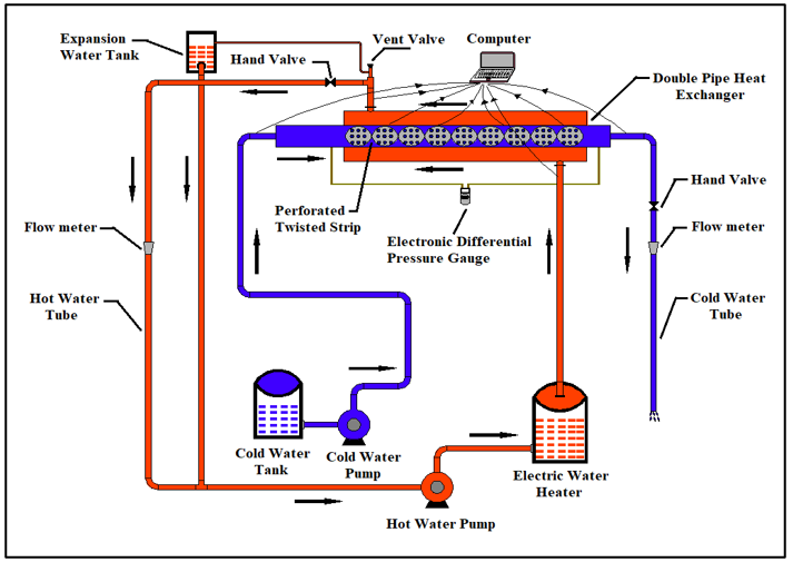
Figure 1, which provides a diagrammatic depiction of the experimental arrangement, shows a double-pipe heat exchanger that is run in a counter-flow configuration. Copper is used for the inner tube, which has a 1.25 mm wall thickness, an inner diameter of 32.5 mm, and an outer diameter of 35 mm. Galvanized steel is used for the outer tube, which has an internal diameter of 76 mm. Glass wool is used as exterior insulation to lessen heat loss into the surrounding air. The heat exchanger has an effective length of one meter. The test rig also contains a cold-water tank maintained at a temperature of (25 ± 2) ℃, from which the cold water travels through the heat exchanger's inner tube, and an electric heater used to heat the water to around (65 ± 2) ℃ before it goes through the annular passage. To autonomously circulate the hot and cold water streams, two circulation pumps are used. A 9-L expansion tank is placed over the test part in the hot water loop to help vent air and make up for water losses. For measuring the flow rates of the hot and cold streams and an electronic differential-pressure gauge for measuring the pressure drop across the test section, the experimental system also has two rotameter-type flow meters. Type-T thermocouples linked to a data logger are used to measure the inner-tube wall temperature as well as the inlet and outlet temperatures of both fluids. The computer is connected to the data logger for continuous measurement and processing of thermal data.
Figure 1. Schematic representation of the experimental setup
As seen in Figure 2, the hot and cold water circulation pumps are activated once the electric heater is turned on and the water reaches the desired temperature that is wanted. The hot-water flow rate is kept constant at 3 L/min, and the cold-water flow rate is changed from 6, 7, 8, 9, to 10 L/min, which is equivalent to turbulent flow with Re > 4000. The experimental system is permitted to run until steady-state thermal conditions are reached once the desired flow rates have been determined. For each operational condition, the necessary temperature and pressure-drop measurements are subsequently documented.

Figure 2. Overview of the experimental setup
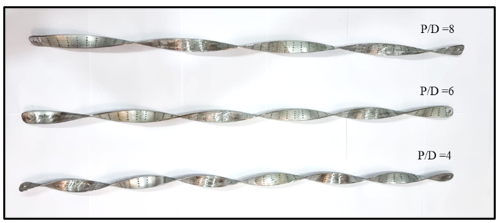
The hot- and cold-water pumps were switched on once the hot water achieved the desired temperature and the electric heater was turned on. The hot-water flow rate was kept constant at 3 L/min, and the cold-water flow rate was changed to 6, 7, 8, 9, and 10 L/min, which resulted in turbulent flow conditions (Re > 4000). Measurements were not collected until thermal steady-state conditions were established for each twisted-strip configuration and operating condition. The measured hot-fluid inlet temperature (Tci) was 25.6 ℃, and the cold-fluid outflow temperature (Tco) was 29 ℃. The outlet and inlet temperatures of the hot fluid were 57.9 ℃ and 64.6 ℃, respectively. The inner tube wall temperatures (Tw1–Tw4) were 46.5 ℃, 47.6 ℃, 46.1 ℃, and 46.4 ℃, respectively. The heat transfer rates determined for the cold and hot fluids were 1416.41 W and 1377. 27 W, respectively, yielding an average heat transfer rate (Qavg) of 1396.84 W. The remaining calculated parameters were 0.099688, 0.049111, an internal surface area (Ai) of 0.10205 m², an internal convective heat transfer coefficient (hi) of 698.36 W/m²·K, and a Nu of 36.9. The uncertainty-analysis document provides these numbers, which are for the plain-pipe scenario. Thermal steady state was established by monitoring the input and outflow temperatures of both fluids and the inner-tube wall temperature until their fluctuations were low enough and the temperatures stayed steady. The temperature measurements were captured using the data acquisition system once the steady-state was reached, and the electronic differential pressure gauge was used to measure the pressure drop over the heat exchanger. The heat-transfer and hydraulic performance factors were determined using the measurements that were obtained after the procedure was repeated for each operating condition and perforated twisted-strip configuration (P/D = 4, 6, and 8). Measurements were only taken after thermal steady state had been established, according to the experimental protocol described in this study. However, the length of the stabilization time, the number of duplicated measurements, and a quantitative temperature-stability criterion were not mentioned. After steady-state conditions are met, the data logger begins to record the inner tube surface temperature and the inlet and outlet temperatures of the hot and cold water streams. Additionally, the heat exchanger's pressure drop is measured using an electrical differential pressure gauge. Figure 3 shows that the experiments were carried out utilizing perforated twisted strips with a constant hole diameter of 2 mm and varied pitch ratios of 4, 6, and 8, where P is the pitch length, and D is the diameter of the twisted strip. Each twisted strip had the experimental method repeated with the same operational settings.
Figure 3. Perforated twisted strip inserts with different pitch ratios
Finally, the experimental data collected using the perforated twisted-strip inserts were compared with those of the plain-pipe design that did not include an insert. In order to evaluate how well perforated twisted strips improve heat transfer while taking into account the related hydraulic losses, the comparison was made in terms of the heat-transfer rate, Nu, friction factor, pressure drop, and thermo-hydraulic performance factor.
The measured experimental data were substituted into the following equations to calculate the thermal and hydraulic performance parameters of the heat exchanger [21].
Mass flow rate of the hot water:
$\dot{\mathrm{m}}_{\mathrm{h}}=\frac{\mathrm{V}}{60000} \times \rho$ (1)
Mass flow rate of the cold water expressed as:
$\dot{\mathrm{m}}_{\mathrm{c}}=\frac{\dot{\mathrm{V}}}{60000} \times \rho$ (2)
Heat transfer rate from the hot water can be calculated by:
$\mathrm{q}_{\mathrm{h}}=\left(\dot{\mathrm{m}} \mathrm{C}_{\mathrm{p}}\right)_{\mathrm{h}}\left(\mathrm{T}_{\mathrm{hi}}-\mathrm{T}_{\mathrm{ho}}\right)$ (3)
Heat transfer rate gained by the cold water can be calculated by:
$\mathrm{q}_{\mathrm{c}}=\left(\dot{\mathrm{m}} \mathrm{C}_{\mathrm{p}}\right)_{\mathrm{c}}\left(\mathrm{T}_{\mathrm{co}}-\mathrm{T}_{\mathrm{ci}}\right)$ (4)
Average heat transfer rate can be calculated from the following equation:
$q_{\text {avg }}=\frac{q_h+q_c}{2}$ (5)
Log-mean temperature difference for counter flow arrangement:
$\mathrm{LMTD}=\frac{\left(\mathrm{T}_{\mathrm{hi}}-\mathrm{T}_{\mathrm{co}}\right)-\left(\mathrm{T}_{\mathrm{ho}}-\mathrm{T}_{\mathrm{ci}}\right)}{\ln \frac{\mathrm{T}_{\mathrm{hi}}-\mathrm{T}_{\mathrm{co}}}{\mathrm{T}_{\mathrm{hi}}-\mathrm{T}_{\mathrm{co}}}}$ (6)
Internal surface area of the inner tube [22]:
$A_i=\pi d_i L$ (7)
Overall heat transfer coefficient based on the inner surface area of the inner tube [23].
$\mathrm{U}_{\mathrm{i}}=\frac{\mathrm{q}_{\text {avg }}}{\mathrm{A}_{\mathrm{i}} \times \text { LMTD } \times \mathrm{F}}$ (8)
where, F = 1 for counter flow operation. The heat capacity rate of the cold water is expressed as:
$\mathrm{C}_{\mathrm{c}}=\left(\dot{\mathrm{m}} \mathrm{C}_{\mathrm{p}}\right)_{\mathrm{c}}$ (9)
Heat capacity rate of the hot water:
$C_h=\left(\dot{m} C_p\right)_h$ (10)
$C_{\min }=\left\{\begin{array}{l}C_h \text { if } C_h<C_c \\ C_c \text { if } C_c<C_h\end{array}\right.$ (11)
Maximum heat transfer:
$\mathrm{q}_{\max }=\mathrm{C}_{\min }\left(\mathrm{T}_{\mathrm{hi}}-\mathrm{T}_{\mathrm{ci}}\right)$ (12)
Actual heat transfer:
$\mathrm{q}=\mathrm{C}_c\left(\mathrm{~T}_{\mathrm{co}}-\mathrm{T}_{\mathrm{ci}}\right)$ (13)
The effectiveness of the heat exchanger can be found from:
$\varepsilon=\frac{\mathrm{q}}{\mathrm{q}_{\max }}$ (14)
The number of transfer units [24]:
$\mathrm{NTU}=\frac{\mathrm{U}_{\mathrm{i}} \mathrm{A}_{\mathrm{i}}}{\mathrm{C}_{\text {min }}}$ (15)
The reequation is expressed as [25]:
$\operatorname{Re}=\frac{\rho \mathrm{ud}_{\mathrm{i}}}{\mu}$ (16)
Inner tube wall temperature:
$\mathrm{T}_{\mathrm{w}_{\mathrm{c}}}=\frac{\mathrm{T}_{\mathrm{w} 1}+\mathrm{T}_{\mathrm{w} 2}+\mathrm{T}_{\mathrm{w} 3}+\mathrm{T}_{\mathrm{w} 4}}{4}$ (17)
The bulk temperature of the cold fluid is calculated as follows:
$\mathrm{T}_{\mathrm{c}, \mathrm{b}}=\frac{\mathrm{T}_{\mathrm{ci}}+\mathrm{T}_{\mathrm{co}}}{2}$ (18)
Convective heat transfer coefficient of the cold fluid:
$\mathrm{h}_{\mathrm{i}}=\frac{\mathrm{q}_{\mathrm{avg}}}{\mathrm{A}_{\mathrm{i}}\left(\mathrm{T}_{\mathrm{w}_{\mathrm{c}}}-\mathrm{T}_{\mathrm{c}, \mathrm{b}}\right)}$ (19)
Nu of the cold fluid equation expressed as:
$\mathrm{Nu}_{\mathrm{c}}=\frac{\mathrm{h}_{\mathrm{i}} \mathrm{d}_{\mathrm{i}}}{\mathrm{k}_{\mathrm{i}}}$ (20)
Darcy friction factor of the inner tube as follows:
$\mathrm{f}=\frac{2 \Delta \mathrm{P} \mathrm{d}_{\mathrm{i}}}{\mathrm{L} \rho \mathrm{u}^2}$ (21)
Performance evaluation criterion (PEC) of the heat exchanger [26]:
$P E C=\frac{\frac{\mathrm{Nu}}{\mathrm{Nu}_0}}{\sqrt[3]{\mathrm{f} / \mathrm{f}_0}}$ (22)
The PEC evaluates the perforated twisted-strip inserts' overall thermo-hydraulic benefit by considering the concurrent effects of heat-transfer improvement and increased flow resistance. Based on the ratio of the improvement in Nu to the associated increase in friction factor relative to the plain tube, the PEC in this study is determined. Because heat-transfer enhancement by itself does not necessarily imply an improved heat-exchanger design when it is accompanied by a significant increase in pressure drop and, as a result, pumping-power needs, this criterion was chosen. As a result, the PEC actually shows the trade-off between the thermal advantage derived from greater convection and the hydraulic penalty incurred by the increased flow resistance. A PEC value over one shows that, given the evaluation conditions, the increase in frictional resistance is outweighed by the improvement in heat-transfer performance. However, a value below one suggests that the hydraulic penalty is greater than the thermal benefit. Thus, the PEC findings offer a better foundation for comparing the various pitch ratios than the Nu or friction factor alone. Gnielinski correlation can be found as [27]:
$\mathrm{Nu}_{\mathrm{D}}=\frac{\left(\frac{\mathrm{f}}{8}\right)\left(\mathrm{Re}_{\mathrm{D}}-1000\right) \operatorname{Pr}}{1+12.7\left(\frac{\mathrm{f}}{8}\right)^{\frac{1}{2}}\left(\operatorname{Pr}^{\frac{2}{3}}-1\right)}$ (23)
Petukhov correlation eq. as follows:
$P v=\left(0.79 \ln R e_D-1.64\right)^{-2}$ (24)
Prandtl number equation as follows:
$p_r=\frac{\mu C_p}{k}$ (25)
4.1 Uncertainty analysis
To determine the dependability of the calculated and observed experimental findings, an uncertainty analysis was carried out. The Kline and McClintock approach, which calculates the uncertainty of a calculated parameter by propagating the uncertainties of its independent measured variables, served as the foundation for the analysis. The major parameters assessed in these experiments were pressure decrease, volumetric flow rate, and temperature. Using Type-T thermocouples linked to a PicoLog TC-08 data logger, the internal tube wall temperature and the hot and cold streams' inlet and exit temperatures were determined. The temperature measurement system's stated accuracy is plus or minus (0.2% of the reading + 0.5 ℃). The two rotameter-type flow meters have a measurement range of 2–18 L/min and an accuracy of ±1% of the reading. Thus, ±1% of the relevant measured value was deemed to be the inaccuracy in the calculated flow rate.
An electronic differential-pressure gauge was used to measure the test section's pressure decrease. The instrument's manufacturer states the differential pressure gauge's numerical accuracy, but the equipment table does not include it, even though the text identifies it as a significant source of uncertainty in hydraulic measurement. As a result, no unsupported numerical accuracy was attributed to this instrument; the manufacturer's stated accuracy should be inserted once the gauge model or calibration certificate is available. For a calculated parameter R = f(x1, x2,…,xn), the combined uncertainty was estimated using the root-sum-square method:
$\mathrm{U}_{\mathrm{R}}=\sqrt{\left(\frac{\partial \mathrm{R}}{\partial \mathrm{x}_1} \mathrm{Ux}_1\right)^2+\left(\frac{\partial \mathrm{R}}{\partial \mathrm{x}_2} \mathrm{Ux}_2\right)^2+\cdots\left(\frac{\partial \mathrm{R}}{\partial \mathrm{x}_{\mathrm{n}}} \mathrm{Ux}_{\mathrm{n}}\right)^2}$ (26)
where, UR stands for the uncertainty related to each measured variable, and UR is the calculated parameter's combined uncertainty. Therefore, the heat-transfer calculations included the uncertainties in flow rate and temperature in order to evaluate their impact on the calculated heat-transfer rate, heat-transfer coefficient, Nu, and Re. Similarly, the flow rate and recorded pressure drop were used to make the hydraulic computations. The pressure drop across the heat exchanger was measured using the electronic differential-pressure gauge, but the manufacturer's accuracy was stated in the experimental equipment Tables 2 and 3. In general, the uncertainty study reveals that temperature and flow rate measurements are the main sources of uncertainty in the thermal calculations, while pressure drop and flow rate measurements account for most of the uncertainty in the hydraulic calculations. While the experimental friction factors deviated from the Petukhov correlation by only 0.75–2.63%, the experimental Nu for the plain tube varied from the Gnielinski correlation by 6.9–12.1%. These departures include not just instrumental uncertainty but also discrepancies between the actual experimental circumstances and the reference correlations' assumptions.
Table 2. Experimental equipment and their specifications
|
Equipment Type |
Model/Manufacturer |
Measurement Range/Specifications |
Accuracy |
|
Thermocouple Data Logger |
PicoLog TC-08 (USB) + Type T thermocouple |
−250 to 400 ℃ |
±(0.2% of reading + 0.5 ℃) |
|
Flow Meter (Rotameter type) |
ZYIA Instrument Company |
2–18 L/min |
±1% of reading
|
|
Electric Water Heater |
- |
50 L Capacity, 3000 W |
- |
|
Water Pump |
- |
220 V, 50 Hz, 0.5 HP, 40 L/min |
- |
Table 3. The instrument accuracy and the corresponding measurement uncertainties of the measured variables
|
Measured Parameter |
Measured Value |
Instrument Accuracy |
Uncertainty |
|
Inner tube diameter |
32.5 mm |
±0.05 mm |
±0.05 mm |
|
Effective tube length |
1000 mm |
±1 mm |
±1 mm |
This section presents and discusses the experimental results, with particular emphasis on the effects of Re and P/D on the thermal and hydraulic performance of the double-pipe heat exchanger.
Figure 4 illustrates the variation of the Nu with Re for all investigated configurations. The results show a consistent increase in Nu with increasing Re for both the plain-tube and perforated twisted-strip configurations. This behavior can be attributed primarily to the increase in fluid velocity and the associated intensification of convective mixing at higher Re. Across the entire investigated Re range, the perforated twisted-strip inserts produced considerably higher Nu than the plain-tube configuration, confirming their effectiveness in enhancing convective heat transfer.

Figure 4. Variation of the Nusselt number (Nu) with Reynolds number (Re)
The observed enhancement is mainly associated with the swirling and secondary flows generated by the twisted strips, which promote stronger interaction between the core fluid and the region adjacent to the tube wall while continuously disturbing the development of the thermal boundary layer. The circular perforations further modify the flow field by allowing a portion of the fluid to pass through the strip. This cross-flow interaction enhances turbulence, promotes additional secondary motion, and strengthens fluid mixing within the tube. Consequently, the thermal boundary layer is repeatedly disrupted and redeveloped, reducing its effective thickness and increasing the temperature gradient near the tube wall. These mechanisms collectively intensify fluid–wall interaction and improve the convective heat-transfer coefficient.
The magnitude of this enhancement is strongly dependent on the pitch ratio. Among the investigated configurations, the P/D = 4 perforated twisted strip produced the highest Nu, achieving a maximum enhancement of approximately 51% relative to the plain-tube configuration. The superior thermal performance of the smaller pitch ratio can be attributed to its stronger swirling motion and more frequent disruption of the near-wall flow, which promote more intensive mixing and boundary-layer disturbance. These results demonstrate that reducing the pitch ratio can substantially enhance heat transfer, although the associated hydraulic penalty must also be considered.
Figure 5 presents the variation of the convective heat-transfer coefficient (h) with Re for the investigated configurations. A clear increase in h is observed as the Re increases, indicating that higher flow rates intensify convective mixing and facilitate greater heat transport between the fluid and the tube wall. The perforated twisted-strip configurations consistently exhibit higher heat-transfer coefficients than the plain-tube configuration, further demonstrating the effectiveness of the inserts in promoting convective heat transfer.

Figure 5. Variation of the heat transfer coefficient with Reynolds number (Re)
The enhancement in h can be attributed to the combined effects of swirl generation, secondary-flow development, and repeated disruption of the thermal boundary layer. In particular, the perforations allow fluid to pass through the twisted strip, modifying the local flow structure and increasing turbulence and interfacial mixing. This mechanism strengthens the exchange of fluid between the core and near-wall regions, increases the temperature gradient at the heat-transfer surface, and consequently enhances convective heat transfer. Overall, the results indicate that the perforated twisted-strip inserts provide an effective passive method for improving the thermal performance of the double-pipe heat exchanger, with the degree of enhancement strongly governed by the pitch ratio and Re.
Consequently, the intensity of swirl and near-wall mixing is reduced, allowing the boundary layer to develop more progressively and resulting in lower heat-transfer enhancement. However, the weaker flow disturbance also reduces the hydraulic penalty associated with the insert. This behavior is reflected in the pressure-drop and friction-factor results, where decreasing the pitch ratio increases flow resistance because of the stronger helical flow path, turbulence, and interaction between the fluid and strip surface.
Figure 6 shows that as the flow velocity and Re rise, the heat-transfer rate increases. The stronger interaction between the fluid and the heat-transfer surface is encouraged by the higher turbulence intensity and improved fluid mixing at higher flow rates, which are related to this behavior. In comparison to the plain-pipe arrangement, the heat-transfer rate is increased even more by the inclusion of perforated twisted-strip inserts. The combined effects of the inserts' swirling motion, secondary flow, and increased turbulence, which enhance fluid mixing, lower thermal resistance, and allow for more effective heat transmission between the tube wall and the flowing fluid, are responsible for this improvement.

Figure 6. Variation of the heat transfer rate with Reynolds number (Re)
The overall heat transfer coefficient (Ui) vs Re is shown in Figure 7. The results show that Ui increases with Re and is further improved by the addition of the perforated twisted-strip inserts. The enhanced thermal interaction between the hot and cold streams, as shown by the improved overall heat-transfer coefficient, aids in a higher heat-transfer rate throughout the heat exchanger. On the other hand, the logarithmic mean temperature difference (LMTD) falls with increasing heat transfer between the two fluids along the heat-exchanger length. The progressive drop in the temperature differential between the hot and cold streams as they swap heat causes this decrease. The greatest heat-transfer coefficient was achieved at the highest Re in the perforated twisted-strip design with a pitch ratio of P/D = 4. This outcome suggests that a lower pitch ratio improves fluid mixing and flow disturbance, hence enhancing the heat-transfer process.

Figure 7. Variation of the overall heat transfer coefficient withReynolds number (Re)
Figure 8 shows how the cold-water stream's temperature difference is affected by the flow rate. The temperature of the cold water drops as the cold-water flow rate rises. It is possible to attribute this action to an increase in the cold-stream heat-capacity rate, which enables the fluid to absorb the transferred heat while undergoing a minor temperature shift. Even though the greater flow rate improves convective heat transfer, it shortens the time that cold water stays in the heat exchanger, which restricts how much the fluid's temperature can increase from the inlet to the outlet.

Figure 8. Variation of the cold water temperature difference with Reynolds number (Re)
As a result, the P/D = 4 arrangement offers the highest thermal enhancement since it creates the most intense swirl, turbulence, and boundary-layer disruption, albeit at the price of a considerably higher friction factor. On the other hand, P/D = 8 results in a less severe flow disruption and thus a lower heat-transfer improvement. However, its lower hydraulic resistance results in a better balance between heat-transfer enhancement and pumping power needs. This explains why P/D = 4 offers the best thermal performance, while P/D = 8 achieves the highest PEC of 1.31, making it the best thermo-hydraulic arrangement among the tested inserts.
As illustrated in Figure 9, the number of transfer units (NTU) rises with an increase in flow rate and Re. The increase in the overall heat-transfer coefficient as the flow rate rises is mostly responsible for this action. The hot stream has the lowest heat-capacity rate among the studied operational parameters; hence, it is the minimum heat-capacity rate utilized in the NTU calculation. For the perforated twisted strip with a pitch ratio of P/D = 4, the highest NTU value of 0.328 was reached at the highest Re of 7639, a 32.1% increase over the smooth-tube configuration. The examined arrangements show that the P/D = 4 insert significantly improves the heat exchanger's heat-transfer capability.

Figure 9. Variation of number of transfer units (NTU) with Reynolds number (Re)

Figure 10. Variation of heat exchanger effectiveness with Reynolds number (Re)
Figure 10 demonstrates how heat-exchanger efficiency changes with NTU. The results suggest that improved heat transfer capacity allows the heat exchanger to take advantage of a larger percentage of the available temperature potential between the two fluid streams, confirming that the efficiency grows with increasing NTU. Although the smooth-tube geometry also shows an increase in effectiveness as Re increases, all perforated twisted-strip configurations have higher effectiveness than the smooth tube over the range studied. The greatest effectiveness of 0.266 for the twisted strip with P/D = 4 was achieved at the highest Re of 7639, representing a 26.5% improvement over the smooth-tube configuration. These results indicate that the perforated twisted strip with a P/D = 4 has the best thermal performance in terms of both heat-exchanger effectiveness and NTU.
The experimental Nu values for the plain pipe were compared to the theoretical values determined with the Gnielinski correlation in order to confirm the experimental setup's trustworthiness and the results' accuracy. Various factors contribute to the 6.9% to 12.1% differences between experimental and Gnielinski-predicted Nu. In contrast to the current experimental configuration, which employs a certain heat exchanger geometry and experimental operating conditions, the Gnielinski correlation is mainly designed for turbulent flow in smooth, plain tubes. Therefore, the observed difference may be attributed to discrepancies between the idealized circumstances depicted by the correlation and the real flow and thermal conditions in the test section. Additionally, the experimentally derived Nu may be impacted by uncertainties in the measurement of temperature, flow rate, fluid property estimation, and the mean heat-transfer coefficient. As a result, the departure found in this investigation is deemed acceptable for experimental validation and does not suggest a methodical inconsistency in the recorded findings. As shown in Figure 11, the good agreement in the overall trend between the experimental and predicted values confirms the reliability of the experimental measurements.

Figure 11. Comparison of the experimental Nusselt number (Nu) with the Gnielinski correlation
In order to assure the dependability of the findings, the theoretical values determined with the Petukhov correlation were compared to the experimental friction factor for the smooth tube. Figure 12 indicates that the Petukhov correlation and the experimental findings have a substantially lower difference, ranging from 0.75% to 2.63%. The Nusselt-number results show good agreement between the determined hydraulic performance and the established correlation for turbulent flow in a smooth tube, according to the decreased deviation. The remaining variances could be due to experimental uncertainties in flow-rate and pressure-drop measurements, as well as the friction-factor calculation's sensitivity to these measured quantities. Overall, the close concurrence between the experimental and Petukhov values lends further credence to the precision and consistency of the hydraulic measurements.

Figure 12. Comparison of the experimental friction factor with the Petukhov correlation
The pressure drop vs. Re relationship for the studied setups is shown in Figure 13. As the pitch ratio lowers, the pressure drop rises, according to the data. This trend may be explained by the smaller twist pitch's greater flow disturbance, which makes the fluid take a more distinct helical flow path and raises the effective flow-path length and hydraulic resistance. Because of the greater fluid velocity and stronger shear stresses between the fluid and the tube wall and insert surfaces, an increase in the flow rate also causes a greater pressure drop. Consequently, a decrease in pitch ratio increases flow mixing but costs more in terms of hydraulics.

Figure 13. Variation of the pressure drop with Reynolds number (Re)
The friction factor's change with Re is displayed in Figure 14. For all examined arrangements, the friction factor decreases with increasing Re. As the flow becomes more driven by inertial effects, viscous effects play a lesser relative role, which is consistent with this tendency. The smoothest pipe has the lowest friction factor readings because it has the least hydraulic resistance due to the absence of internal obstructions in its flow route. On the other hand, the perforated twisted-strip inserts significantly enhance the friction factor because the twisted form creates swirl, secondary flow, and additional turbulence inside the tube. While the perforations improve heat transfer and allow for fluid exchange via the strip, they also lead to more pressure loss because they raise fluid–insert interaction and flow disturbance.
The twisted strip with P/D = 4 had the highest friction factor out of all the configurations that were examined. Its friction factor was 98.8% greater than that of the smooth tube at the lowest Re of 4600. The outcome reveals that reducing the pitch ratio amplifies the whirling motion and flow disruption, raising hydraulic resistance. As a result, the P/D = 4 configuration provides improved heat-transfer augmentation at the cost of a larger frictional penalty, emphasizing the necessity of simultaneously assessing thermal and hydraulic performance.

Figure 14. Variation of the friction factor with Reynolds number (Re)
Figure 15 shows how the investigated perforated twisted-strip configurations' PEC varies with Re. The results indicate that all perforated twisted strip PEC values are larger than unity over the Re range investigated, suggesting that all inserts offer a thermo-hydraulic benefit over the plain-pipe setup. The maximum PEC value of 1.31, which corresponds to a 31% improvement over the plain pipe, was achieved at low Re for the twisted strip with a pitch ratio of P/D = 8. This was followed by the P/D = 6 configuration, which achieved a PEC of 1.24 (a 24% improvement), and the P/D = 4 configuration, which recorded a PEC of 1.20 (a 20% improvement).
For all studied inserts, a progressive fall in PEC is seen as the Re rises. Although increasing Re improves the heat transfer rate, the accompanying rise in pressure drop and pumping-power needs is proportionately greater, as shown by this behavior. As a result, some of the thermal improvement is outweighed by the increased hydraulic penalty at higher Re, which lowers the overall performance standard. The P/D = 8 perforated twisted strip offers the best thermo-hydraulic performance among the examined setups, especially at lower Re, since it strikes an excellent balance between heat-transfer improvement and the accompanying pressure-drop penalty.

Figure 15. Variation of the performance evaluation criterion (PEC) with Reynolds number (Re)
The experimental study demonstrates that the thermo-hydraulic performance of the double-pipe heat exchanger is significantly impacted by the integration of perforated twisted-strip inserts. The findings demonstrate that the pitch ratio is a crucial geometric parameter influencing swirl flow intensity, hydraulic resistance, and heat-transfer improvement. The major findings from the experiments may be condensed as follows:
a) Heat transfer is improved by reducing the pitch ratio, which also increases the intensity of the swirling flow. Compared to the plain-pipe setup, the perforated twisted strip with P/D = 4 resulted in a 51% increase in the Nu. Nevertheless, this improvement was associated with a 98. 8% rise in friction factor, which shows the hydraulic cost.
b) At the lowest Re, the perforated twisted strip with P/D = 8 achieved the highest PEC of 1.31, representing a 31% improvement over the plain pipe. The PEC values for the P/D = 6 and P/D = 4 arrangements were 1.24 and 1.20, respectively. Among the investigated inserts, the P/D = 8 setting offers the most ideal trade-off between pressure-drop penalty and heat-transfer improvement. These findings suggest that.
c) At a Re of 7639, the P/D = 4 perforated twisted strip yielded the highest NTU value of 0.328, which was 32.1% higher than the plain-pipe setup. At higher flow rates, this confirms the superior heat transfer capacity of the lesser pitch-ratio arrangement.
d) The highest heat-exchanger efficiency of 0.266 was also attained by the P/D = 4 arrangement at a Re of 7639, representing a 26.5% enhancement over the simple pipe.
In conclusion, the experimental findings support the idea that double-pipe heat exchangers may benefit from the passive heat-transfer improvement method provided by perforated twisted-strip inserts. However, the findings also show a definite thermo-hydraulic compromise: lowering the pitch ratio increases frictional losses and pressure drop while enhancing heat-transfer performance. The selection of the ideal pitch ratio should take into account both hydraulic penalties and thermal improvements. In terms of thermo-hydraulic performance, P/D = 8 outperforms the other PEC configurations, while P/D = 4 offers the greatest heat transfer enhancement, NTU, and heat exchanger effectiveness.
|
Ai |
inner surface area of the inner tube, m2 |
|
Cc |
heat capacity rate of cold water, W‧K-1 |
|
Ch |
heat capacity rate of hot water, W‧K-1 |
|
Cmin |
minimum heat capacity rate, W‧K-1 |
|
Cp |
specific heat, J‧kg-1‧K-1 |
|
di |
inner diameter of the inner tube, m |
|
ƒ |
friction factor, (dimensionless) |
|
ƒ0 |
friction factor for the plain pipe, (dimensionless) |
|
hi |
Convective heat transfer coefficient (inner side), W‧m-2‧K-1 |
|
k |
thermal conductivity, W‧m-1‧K-1 |
|
L |
heat exchanger Length, m |
|
LMTD |
log-mean temperature difference, K |
|
$\dot{\mathrm{m}}$ |
mass flow rate, Kg‧s-1 |
|
NTU |
number of transfer units, (dimensionless) |
|
Nu |
Nusselt number, (dimensionless) |
|
Nu0 |
Nusselt number for the plain pipe, (dimensionless) |
|
PEC |
performance evaluation criterion, (dimensionless) |
|
P/D |
pitch ratio, (dimensionless) |
|
Pr |
Prandtl number, (dimensionless) |
|
q |
heat transfer rate, W |
|
Re |
Reynolds number, (dimensionless) |
|
Pv |
Petukhov correlation |
|
T |
temperature, ℃ |
|
TW |
wall temperature, ℃ |
|
Ui |
overall heat transfer coefficient (inner side), W‧m-2‧K-1 |
|
u |
fluid velocity, m‧s-1 |
|
$\dot{\mathrm{V}}$ |
volumetric flow rate m3‧s-1 |
|
ΔP |
pressure drop, pa |
|
Greek symbols |
|
|
ξ |
heat exchanger effectiveness |
|
µ |
dynamic viscosity, Pa‧s |
|
ρ |
density, Kg‧m-3 |
|
Subscripts |
|
|
avg |
average |
|
b |
bulk |
|
c |
cold fluid |
|
h |
hot fluid |
|
i |
inlet |
|
max |
maximum |
|
min |
minimum |
|
o |
outlet |
[1] Ghalambaz, M., Mashayekhi, R., Arasteh, H., Ali, H.M., Talebizadehsardari, P., Yaïci, W. (2020). Thermo-hydraulic performance analysis on the effects of truncated twisted tape inserts in a tube heat exchanger. Symmetry, 12(10): 1652. https://doi.org/10.3390/sym12101652
[2] Arasteh, H., Rahbari, A., Mashayekhi, R., Keshmiri, A., Babaei Mahani, R., Talebizadehsardari, P. (2021). Effect of pitch distance of rotational twisted tape on the heat transfer and fluid flow characteristics. International Journal of Thermal Sciences, 170: 106966. https://doi.org/10.1016/j.ijthermalsci.2021.106966
[3] Kumar, V., Sahoo, R.R. (2022). Design optimization, thermohydraulic, and enviro-economic analysis of twisted perforated tape insert-based heat exchanger with nanofluid using computational fluid dynamics and Taguchi grey method. ASME Journal of Heat and Mass Transfer, 145(1): 011901. https://doi.org/10.1115/1.4056066
[4] Li, S.J., Qian, Z.Q., Wang, Q. (2023). Optimization of thermohydraulic performance of tube heat exchanger with L twisted tape. International Communications in Heat and Mass Transfer, 145: 106842. https://doi.org/10.1016/j.icheatmasstransfer.2023.106842
[5] Adibi, T., Mashoofi Maleki, N., Tavousi, E., Keshmiri, A. (2025). Enhancing the heat transfer efficiency in heated tube with a novel multi-twisted blade Turbulators: A numerical analysis. International Communications in Heat and Mass Transfer, 169: 109717. https://doi.org/10.1016/j.icheatmasstransfer.2025.109717
[6] Laue, L.K., Hattel, J., Abolmaali, A.M. (2026). CFD investigation of thermo-hydraulic performance enhancement in a double-pipe heat exchanger using non-uniformly spaced perforated ring inserts. Energy Conversion and Management, 355: 121293. https://doi.org/10.1016/j.enconman.2026.121293
[7] Bhuiya, M.M.K., Roshid, M.M., Talukder, M.M.M., Rasul, M.G., Das, P. (2020). Influence of perforated triple twisted tape on thermal performance characteristics of a tube heat exchanger. Applied Thermal Engineering, 167: 114769. https://doi.org/10.1016/j.applthermaleng.2019.114769
[8] Miri, R., Mliki, B., Mohamad, B.A., et al. (2023). Entropy generation and heat transfer rate for MHD forced convection of nanoliquid in presence of viscous dissipation term. CFD Letters, 15(12): 77-106. https://doi.org/10.37934/cfdl.15.12.77106
[9] Khaled, R.A., Mushatet, K.S. (2023). CFD analysis for a twisted elliptical double tube heat exchangers integrated with a twisted tape. International Journal of Heat and Technology, 41(5): 1301-1308. https://doi.org/10.18280/ijht.410520
[10] Sontakke, S., Patel, P., Sharma, A., Singh, M., Kothadia, H. (2023). Experimental and numerical investigation of heat transfer enhancement with twisted tape insert. Heat Transfer Research, 54(14): 17-42. https://doi.org/10.1615/HeatTransRes.2023045756
[11] Dhumal, G.S., Havaldar, S.N. (2023). Enhancing heat transfer performance in a double tube heat exchanger: Experimental study with twisted and helical tapes. Case Studies in Thermal Engineering, 51: 103613. https://doi.org/10.1016/j.csite.2023.103613
[12] Bouregueba, A., Begag, A., Saim, R., Kherrafi, M.A. (2025). Heat transfer enhancement in a heat exchanger tube using twisted tapes with circular and hexagonal perforations. International Journal of Thermodynamics, 28(3): 187-195. https://doi.org/10.5541/ijot.1653747
[13] Kumbhar, D.G., Sutar, K.B., Kumar, A., Lavate, R.S., Pawar, S.R. (2024). Experimental studies on heat transfer performance of a heat exchanger with drilled twisted tape inserts. Engineering Research Express, 6(4): 045568. https://doi.org/10.1088/2631-8695/ad9b06
[14] Pimoli, D.S., Tomar, P., Kumar, A., Dwivedi, G., Shukla, A. (2025). Experimental investigation of friction factor and heat transfer enhancement using circular perforated twisted tape inserts in heat exchangers. International Journal of Energy for a Clean Environment, 26(3): 69-84. https://doi.org/10.1615/InterJEnerCleanEnv.2024053616
[15] Sedaghat, R., Dalili, K.M., Hosseinalipour, S.M. (2024). A comprehensive analysis of heat transfer in a heat exchanger with simple and perforated twisted tapes based on numerical simulations. Case Studies in Thermal Engineering, 56: 104227. https://doi.org/10.1016/j.csite.2024.104227
[16] Abass, O.W., Tekir, M. (2025). Numerical investigation on effects of plain, perforated, and dimpled twisted tape inserts in a tube to flow and heat transfer characteristics. Numerical Heat Transfer, Part A: Applications, 86(18): 6650-6669. https://doi.org/10.1080/10407782.2024.2377705
[17] Mehta, R., Gupta, A., Kumar, N., Eiamsa-ard, S., Pimsarn, M., Chamoli, S. (2026). Influence of perforated twisted tapes with vortex generator wings on heat transfer performance and entropy in a heat exchanger tube. International Journal of Thermal Sciences, 219: 110192. https://doi.org/10.1016/j.ijthermalsci.2025.110192
[18] Kapade, T.T., Shah, S.K., Shah, D.S., et al. (2025). Thermal analysis of v-cut twisted tape fitted heat exchanger: A numerical approach. International Journal on Interactive Design and Manufacturing, 19: 1895-1911. https://doi.org/10.1007/s12008-024-01883-2
[19] Singh, S.K., Anand, R., Sikarwar, V.S., Arora, A., Kacker, R. (2025). Optimizing performance of DPHE using twisted tape with V-cuts and circular holes: An experimental and gradient boosting approach. Energy Sources, Part A: Recovery, Utilization, and Environmental Effects, 47(2): 2552998. https://doi.org/10.1080/15567036.2025.2552998
[20] Qiu, W.X., Samruaisin, P., Chuwattanakul, V., Maruyama, N., Hirota, M., Eiamsa-Ard, S. (2025). Evaluation of heat transfer performance of a heat exchanger tube mounted with an I-rib twisted tape and twisted winglets. Scientific Reports, 15: 37047. https://doi.org/10.1038/s41598-025-20806-z
[21] Qader, F.F., Hussein, A.M., Danook, S.H., Mohamad, B., Khaleel, O.S. (2023). Enhancement of double-pipe heat exchanger effectiveness by using porous media and TiO₂ water. CFD Letters, 15(4): 31-42. https://doi.org/10.37934/cfdl.15.4.3142
[22] Soltani, M.M., Gorji-Bandpy, M., Vaisi, A., Moosavi, R. (2022). Heat transfer augmentation in a double-pipe heat exchanger with dimpled twisted tape inserts: An experimental study. Heat and Mass Transfer, 58: 1591-1606. https://doi.org/10.1007/s00231-022-03189-z
[23] Qader, F.F., Mohamad, B., Hussein, A.M., Danook, S.H. (2024). Numerical study of heat transfer in circular pipe filled with porous medium. Pollack Periodica, 19(1): 137-142. https://doi.org/10.1556/606.2023.00869
[24] Berkache, A., Amroune, S., Golbaf, A., Mohamad, B. (2022). Experimental and numerical investigations of a turbulent boundary layer under variable temperature gradients. Journal of the Serbian Society for Computational Mechanics, 16(1): 1-15. https://doi.org/10.24874/jsscm.2022.16.01.01
[25] Wongcharee, K., Chuwattanakul, V., Chamoli, S., Maruyama, N., Hirota, M., Eiamsa-Ard, S. (2025). Investigation of turbulent thermal-hydraulic behaviors of a heat exchanger tube with U-cut twisted-tape. Case Studies in Thermal Engineering, 67: 105838. https://doi.org/10.1016/j.csite.2025.105838
[26] Ghazanfari, V., Mansourzade, F., Taheri, A., Amini, Y., Shadman, M.M. (2025). Enhancing thermal efficiency in helical heat exchangers: A CFD study on twisted tube configurations. Case Studies in Thermal Engineering, 73: 106694. https://doi.org/10.1016/j.csite.2025.106694
[27] Assaf, Y.H., Akroot, A., Alnamasi, K., Ismail, M.A. (2025). Investigation of heat transfer performance in heat exchangers using hybrid nanofluids and twisted tape inserts with fixed special rings. Scientific Reports, 15: 18450. https://doi.org/10.1038/s41598-025-02135-3