Zhala Azeez Mohammed | Furqan Haider Mohammed Ali | Intisar Khalaf | Ehsan Fadhil Abbas*
© 2026 The authors. This article is published by IIETA and is licensed under the CC BY 4.0 license (http://creativecommons.org/licenses/by/4.0/).
OPEN ACCESS
This study presents a combined numerical and experimental investigation of the thermohydraulic behavior of pin-fin heat sinks as the fin geometry transitions from circular to elliptical. The isolated effect of fin ellipticity was evaluated by holding fin length and surface area constant while varying the aspect ratio (R = 0.2–1.0) across different Reynolds numbers and heat fluxes. Numerical simulations using COMSOL Multiphysics were validated with an aluminum pin-fin heat sink. Results show that circular fins produced the highest Nusselt numbers due to stronger vortex formation and higher turbulence intensity, thereby enhancing convective heat transfer but also increasing pressure losses and pumping power requirements. In contrast, elliptical fins delayed flow separation and improved pressure recovery because of their streamlined geometry, resulting in lower flow resistance and enhanced hydrothermal efficiency despite a moderate reduction in local heat-transfer coefficients. Experimental validation showed good agreement with numerical predictions, with deviations not exceeding 6% for the Nusselt number and 2% for the pressure drop. The findings demonstrate that effective heat-sink optimization requires balancing heat-transfer enhancement with hydraulic performance and provide practical design guidance for compact, energy-efficient thermal management systems.
Over the past two decades, advances in heat sink design have encompassed a range of configurations and fin profiles, driven by demand for effective thermal management across sectors. In industry, heat sinks manage high heat loads in power electronics, motors, and energy systems, improving stability and lifespan. In service and infrastructure applications, compact, lightweight designs are used in heating, ventilation, and air conditioning (HVAC), renewable energy, and light-emitting diode (LED) modules to enable efficient heat dissipation in confined spaces. In electronics, miniaturization and high power density in CPUs, GPUs, and amplifiers have driven the adoption of advanced fin geometries, such as conical and micro-pin structures, that enhance airflow and heat transfer. These innovations have transformed heat sinks into sophisticated thermal management systems, enhancing performance, reliability, and energy efficiency [1-3]. A heat sink is typically made from materials with high thermal conductivity, such as copper or aluminum, to ensure efficient heat dissipation. It consists of a base plate and a series of fins that significantly increase the convective heat transfer area. Different fin geometries are used, including plate fins with either constant or variable cross-sectional areas, as well as pin-fin configurations, depending on the desired thermal and hydraulic performance. Figure 1 illustrates examples of commonly used heat sink designs.
The use of heat sinks for effective heat dissipation from thermal units has grown increasingly important in modern thermal management systems. This significance has attracted extensive research, leading to numerous experimental, theoretical, and numerical investigations aimed at optimizing heat sink design. These studies have focused on key design parameters, including fin shape, arrangement, dimensions, material properties, and the cooling fluid's characteristics, to enhance thermal performance and energy efficiency. A review of several recent and significant studies on heat sink development and optimization is presented in this context. Deshmukh and Warkhedkar [4] evaluated air-side heat sink performance experimentally and theoretically for elliptical pin fins under mixed convection in inline and staggered setups. They varied fin spacing, aspect ratio, void fraction, approach velocity, and mixed-convection parameter. Results showed that elliptical fins have lower thermal resistance and higher heat transfer than circular fins. They also identified optimal fin pitch and aspect ratio. Baruah et al. [5] examined the effects of the major-to-minor axis ratio, fin spacing, and the Re number on the performance of an elliptical pin-fin heat sink through experiments and simulations. They found that increasing the aspect ratio boosts heat transfer and the Nu number by improving fluid mixing and surface exposure, but also raises the pressure drop, illustrating a trade-off between thermal efficiency and flow resistance in design. Bahiraei et al. [6] studied the thermal performance of an elliptical pin-fin heat sink with silver-water nanofluids using a numerical two-phase approach. They varied the nanoparticle concentration, fin shape, Re number, and heat flux, and analyzed the Nu number, pressure drop, and thermal resistance. Results showed that nanofluids significantly improve heat transfer and reduce thermal resistance in the heat sink but also increase pumping power, necessitating a balance between thermal gains and energy efficiency. Kewalramani et al. [7] investigated the thermohydraulic behavior of micro heat sinks with short pin fins of different shapes (square and elliptical) and layouts (inline and staggered), using deionized water as the coolant and combining experiments on etched silicon prototypes with computational fluid dynamics (CFD) validation. The parameters studied included fin shape, fin arrangement, pressure drop, and temperature. Results showed that fin shape, especially elliptical, has a greater effect on thermal resistance than fin layout. Pallikonda et al. [8] analyzed microchannels with elliptical fins to enhance heat transfer. They studied the effects of fin angles and flow on thermal–hydraulic metrics, including the Nusselt number, thermal resistance, and pressure drop. An elliptical fin at 2° was most efficient, increasing the average Nu number by 116% (from 7.68 to 16.64) with minimal pressure drop. Ateş et al. [9] experimentally investigated the effects of elliptical pin fins, distributed pin fins, and tip clearance on flow-boiling performance in heat sinks with deionized water at mass fluxes from 125 to 325 kg/m²·s and heat fluxes from 18 to 175 W/cm². The results revealed that a heat sink with distribution pin fins and without tip clearance is the most performant for heat transfer. Enhanced boiling heat transfer was achieved with streamlined distributions in the laminar flow, compared to the reference plain channel. Yu et al. [10] analyzed a composite elliptical pin-fin microchannel heat sink for high-heat-flux cooling, comparing it with smooth, cylindrical, and elliptical pin-fin MCHSs. The CEP-MCHS provided better heat transfer and temperature uniformity, driven by flow disturbances and boundary-layer destruction. At Re of 850, the average Nusselt number is about 33, which is 1.5 times higher than other fin configurations and twice that of inflation designs in serpentine flow, with superior performance, including the lowest thermal resistance and entropy. Ali et al. [11] numerically studied the microchannel heat sinks with semi-elliptical pin-fin (SEPF) structures at various aspect ratios to predict heat transfer and flow characteristics. Including SEPFs led to a significant increase in convective surface area and a marked improvement in heat transfer compared with the traditional microchannel heat sink; however, a smaller aspect ratio weakened wake shedding and thermal efficiency. The most favorable thermohydraulic performance was obtained at the best SEPF aspect ratio, where the balance between increased heat transfer and increased pressure drop was achieved. Chahrour and Omran [12] conducted a numerical assessment of twisted elliptical pin-fin heat sinks with varying levels of perforation. They investigated the effects of flow rate, fin twist angle, and perforation ratio on thermal resistance, the Nu number, pressure drop, and hydrothermal performance factor. Their findings indicate that moderate perforation significantly enhances heat transfer while maintaining acceptable pressure penalties. Additionally, they found that twisting the fins improves fluid mixing and overall efficiency. Abdulsahib et al. [13] conducted a comprehensive review of the effects of various parameters on convective heat transfer in different enclosures and heat sinks. The study assessed how design factors, including fin shapes (rectangular, triangular, circular, elliptical, and wavy), cavity geometry, materials, and boundary conditions, influence heat transfer. Through a systematic literature analysis and comparative evaluation, the researchers found that optimizing fin geometry and selecting appropriate materials significantly enhance heat dissipation. Gijoy et al. [14] numerically investigated a 3D asymmetric elliptical-cylindrical pin-fin heat sink subjected to turbulent flow based on a validated 3D CFD model. The fin effectiveness of the optimum geometry (radius to height = 0.9) was obtained as 1.43 with respect to a conventional cylindrical pin-fin reference. Perforation was an additional factor for improvement, and in this case (Re = 3111), the most effective one was to punch a hole in each fin. It shows a high value of the same, with a fin effectiveness of 2.25, while reducing fin volume, leading to enhanced thermal performance and material savings. Danışmaz [15] studied the effects of fin cross-section shape (circular and elliptical) and perforations on heat-si improvement behavior, transforming the data into information through CFD simulations with turbulent flow. Elliptical fins with a radius ratio of 0.50 achieved a substantial enhancement in heat transfer and performance, up to 90% relative to circular fins. Although the pressure drop decreased with perforated fins, it increased with elliptical designs. Table 1 summarizes the reviewed studies and identifies research gaps and areas requiring further investigation.

Figure 1. Samples of heat sink geometries
Table 1. Summary of previous studies
|
Reference |
Study Objective |
Methodology |
Studied Parameters |
Key Findings |
|
Deshmukh and Warkhedkar [4] |
Evaluate elliptical pin-fin heat sinks under mixed convection. |
Experimental and analytical study. |
Fin spacing, aspect ratio, and Re number. |
Elliptical fins reduced thermal resistance; optimal spacing improved performance. |
|
Baruah et al. [5] |
Studied the influence of principal/minor axes on elliptical fin performance. |
Experimental and numerical analysis. |
Aspect ratio, fin spacing, and Re number. |
Higher aspect ratios improved heat transfer but increased pressure drop. |
|
Kewalramani et al. [7] |
Assessed short pin-fin shapes and arrangements. |
Experimental and numerical analysis. |
Fin shape (square, elliptical, triangular), arrangement. |
Elliptical fins yielded a higher Nu number and efficiency. |
|
Pallikonda et al. [8] |
Enhanced heat transfer using elliptical fin microchannels. |
Numerical simulation. |
Fin orientation, flow rate. |
2° elliptical fin angle increased the Nu number by 116%. |
|
Ateş et al. [9] |
Evaluate effects of elliptical fins, fin distribution, and tip clearance on flow-boiling heat sink performance. |
Experimental flow-boiling tests. |
Fin geometry, fin distribution, tip clearance, mass flux, and heat flux. |
Optimized fin distribution with zero tip clearance maximized heat transfer and boiling stability; excessive clearance degraded performance. |
|
Yu et al. [10] |
Enhanced microchannel heat sink performance using composite elliptical pin fins. |
3D computational fluid dynamics (CFD) simulation. |
Fin geometry, Reynolds number, Nusselt number, thermal resistance, entropy generation. |
Composite elliptical fins increased Nu (~1.5× vs. finned; ~2× vs. smooth) and reduced thermal resistance and entropy generation. |
|
Ali et al. [11] |
Investigate semi-elliptical pin fins for thermal enhancement in microchannels. |
Numerical CFD analysis. |
Fin aspect ratio, Reynolds number, Nusselt number, and pressure drop. |
Semi-elliptical fins significantly enhanced heat transfer; optimal aspect ratio balanced thermal enhancement and hydraulic penalty. |
|
Chahrour and Omran [12] |
Investigated twisted elliptical pin fins with varying perforation levels. |
Numerical CFD analysis. |
Twist angle, perforation ratio, and Re number. |
Moderate perforation and twisting improved heat transfer with minimal loss. |
|
Abdulsahib et al. [13] |
Review convection effects in enclosures and heat sinks. |
Literature review and comparative analysis. |
Fin shape, material, boundary conditions. |
Geometry and material selection critically affect heat dissipation and efficiency. |
|
Danışmaz [15] |
Effects of fin ellipticity and perforation on the thermal and hydraulic performance of pin-fin heat sinks. |
Analyzed the Numerical CFD simulation under turbulent airflow. |
Fin cross-section (circular vs. elliptical), ellipticity ratio, perforation diameter and number, Reynolds number, Nusselt number, pressure drop, heat transfer performance factor (HTPF). |
Elliptical fins significantly enhanced heat transfer, achieving up to ~90% improvement in HTPF compared with circular fins. Perforations reduced pressure drop but slightly decreased heat transfer, indicating a trade-off between thermal enhancement and hydraulic penalty. |
The reviewed studies show a clear evolution in heat-sink research from conventional pin-fin geometries toward more streamlined and optimized configurations. Early works primarily examined the effects of elliptical fin spacing, aspect ratio, and Reynolds number, showing that elliptical fins can reduce thermal resistance and improve heat-transfer performance compared with circular fins. Later studies broadened the analysis by introducing nanofluids, microchannel configurations, fin orientation, semi-elliptical profiles, twisted fins, and perforated fins. This progression indicates a shift from simple geometric comparisons to integrated thermo-hydraulic optimization, in which heat-transfer enhancement must be balanced against pressure drop and pumping-power requirements.
A major similarity among the reviewed studies is that most agree on the importance of fin geometry in controlling boundary-layer development, flow separation, vortex formation, and pressure loss. Many studies also confirm that elliptical or modified pin fins can improve thermal performance or reduce flow resistance, depending on the operating conditions. However, the studies differ in their conclusions regarding the best geometry. Some works report that elliptical fins enhance Nu and reduce thermal resistance, while others show that circular or more bluff geometries may generate stronger vortices and therefore higher local heat transfer, but at the cost of higher pressure drop. Similarly, perforation and twisting were found to improve hydrothermal behavior in some cases, whereas other studies reported a reduction in heat transfer when pressure-drop reduction was prioritized.
Although previous studies have demonstrated the potential of elliptical, modified, and perforated pin fins to improve heat-sink performance, the literature remains fragmented. Most investigations treated each fin geometry as a separate design case, making it difficult to isolate the direct thermo-hydraulic effect of changing a circular cross-section to an elliptical one. Moreover, many studies did not preserve key geometric constraints, such as constant fin length and surface area, which are essential for a fair comparison. Therefore, the present study addresses this gap by systematically transforming circular pin fins into elliptical configurations with different aspect ratios while maintaining constant fin length and surface area. This enables a clearer evaluation of how ellipticity affects Nu, pressure drop, and overall hydrothermal performance under forced convection.
This study numerically investigates the impact of replacing cylindrical pin fins with elliptical pin fins on the thermohydraulic characteristics of a heat sink installed in a vertical channel. The circular cross-section is transformed into an elliptical shape with four aspect ratios (major axis (a) /minor axis (b)) ranging from 0.2 to 0.8, in increments of 0.2, while maintaining a constant fin length and surface area. The sketches and corresponding dimensions of the studied samples are provided in Table 2 and Figure 2. The performance of the elliptical pin fin samples was assessed numerically and compared with experimental results from the cylindrical pin fin heat sink.
Table 2. Detailed dimensions of the heat sink samples
|
R |
H (mm) |
L (mm) |
Sn |
Sp |
b (mm) |
a (mm) |
l (mm) |
P (mm) |
As (mm2) |
|
0.2 |
120 |
100 |
25 |
20 |
7.476413 |
1.495283 |
130 |
31.42857 |
4085.714 |
|
0.4 |
120 |
100 |
25 |
20 |
6.825658 |
2.730263 |
130 |
31.42857 |
4085.714 |
|
0.6 |
120 |
100 |
25 |
20 |
6.15347 |
3.692082 |
130 |
31.42857 |
4085.714 |
|
0.8 |
120 |
100 |
25 |
20 |
5.538448 |
4.430759 |
130 |
31.42857 |
4085.714 |
|
1 |
120 |
100 |
25 |
20 |
5 |
5 |
130 |
31.42857 |
4085.714 |

Figure 2. Geometrical specifications of the heat sink sample
This section outlines the numerical simulations conducted for the study. The simulations aimed to model the key parameters and operating conditions related to the research objectives, utilizing advanced computational techniques to ensure both accuracy and reliability. By exploring various scenarios, we evaluated the system's behavior under different conditions, which provides a basis for further investigation. The simulations were carried out using COMSOL Multiphysics software.
3.1 Physical description
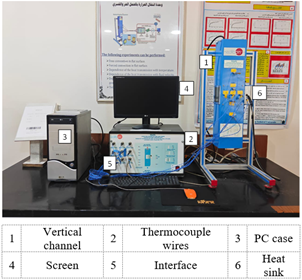
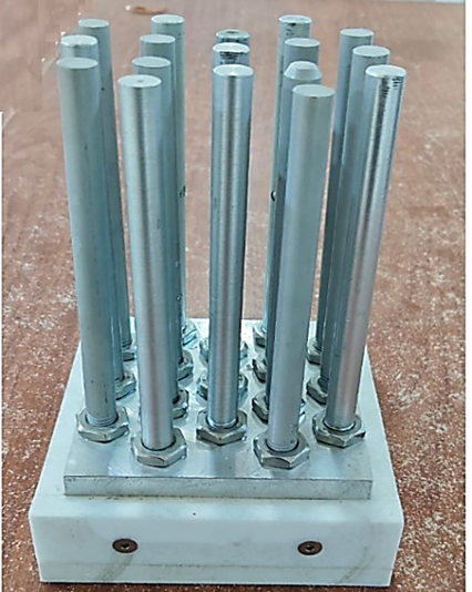
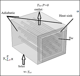
The experimental investigation was conducted on a cylindrical pin-fin heat sink, a component of the computerized convection heat transfer apparatus manufactured by Edibon (Spain). The apparatus is housed in the Heat Transfer Laboratory of the Mechanical Power Techniques Engineering Department at the Technical Engineering College/Kirkuk, as shown in Figure 3. The heat sink was fabricated from pure aluminum and consists of a base measuring 100 × 100 × 15 mm. It is equipped with 17 cylindrical fins, each measuring 10 mm in diameter and 130 mm in length, arranged in a staggered configuration across six rows in a 4 × 3 pattern, with a transverse pitch (Xt) of 25 mm and a longitudinal pitch (Xl) of 20 mm. A photograph of the heat sink is shown in Figure 4. The practical experiments were conducted under forced convection conditions at constant surface temperatures of 28 ℃, 53 ℃, and 83 ℃, with air volumetric flow rates of 20 cm³/min, 60 cm³/min, and 120 cm³/min. Numerical models were developed based on the specifications presented in Table 1. The cylindrical pin-fin model was validated against the experimental heat sink to assess mesh independence. A schematic representation of the numerical models is shown in Figure 5.
Figure 3. Photo of the test rig used
Figure 4. Cylindrical pin fin heat sink

Figure 5. Sketch of numerical heat sink models
3.2 Governing equations
The steady-state governing equations are presented in Eqs. (1)–(4) [16-18]. These include the continuity, momentum, and energy equations, which describe the turbulent, Newtonian, and incompressible airflow with heat transfer through the pin-fin heat sink in the COMSOL Multiphysics simulation. Under steady-state conditions, the governing equations are given as follows:
Continuity equation
$\nabla \vec{V}=0$ (1)
Momentum equation
$\rho \nabla \vec{V}=\rho \vec{g}-\nabla \vec{p}+\mu \nabla^2 \vec{V}$ (2)
Energy equation for liquid
$\rho c_p \vec{V} \vec{\nabla} T=k_s \Delta T$ (3)
Energy equation for a solid
$k_s \Delta T=0$ (4)
The governing Eqs. (1)–(4) are solved by enforcing the boundary conditions outlined in Figure 6 and Table 3. The numerical models will be simulated according to the operating conditions specified in Table
Figure 6. The boundary conditions
Table 3. Boundary conditios for the numerical model
|
Parameters |
Boundary Conditions |
|
Inlet |
V=w = fully developed at inlet to working space, u = v=0, T =Ta,i |
|
Outlet |
$\frac{\partial u}{\partial z}=\frac{\partial v}{\partial z}=\frac{\partial w}{\partial z}=0, \frac{\partial T}{\partial z}=0, P=P_{a t m}$ |
|
Walls |
No slip and adiabatic |
|
Heat sink |
Base plate at a constant temperature of Tw |
|
Flow regime |
Laminar |
Table 4. Working conditions
|
Parameters |
Units |
|
Inlet air temperature Ta,i |
20 ℃ |
|
Air volumetric flow rate $\dot{V}$ |
20, 60, and 120 cm3/s |
|
Temperature of base plate Tw |
28, 53, and 83 ℃ |
3.3 Mesh independence testing
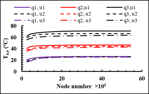
Mesh independence testing ensures that the number of nodes or resolution does not affect the results of numerical simulations. By refining the mesh and comparing the results, this test determines when the solution stabilizes, indicating that further mesh refinement will not significantly alter the outcome and ensuring reliable, accurate simulations. In the present study, the cylindrical numerical model was simulated with five different mesh densities and compared with the experimental Nu number to identify the mesh density that best aligned with the experimental results. The mesh densities are categorized as coarser, coarse, normal, fine, and finer, with corresponding mesh values of 263187, 477708, 1029426, 2501592, and 5438538, respectively. The results indicate that the fine-type mesh is suitable for all test conditions, as Ta,o stabilized across all tests, as shown in Figure 7.
Figure 7. Grid independence test based on the outlet air temperature under different operating conditions
The sensible heat transfer equation is employed to quantify the heat dissipation from a heat sink and is expressed as:
$Q=\dot{m} c_p\left(T_{a, o}-T_{a, i}\right)$ (5)
where,
$\triangleright \Lambda \times d=u$ (6)
Newton's law of cooling is used to estimate the convective heat transfer coefficient, which characterizes the rate of heat transfer between a solid surface and a surrounding fluid due to temperature differences. This relationship is mathematically expressed as [19]:
$h=\frac{Q}{A_t\left(T_w-\frac{T_{a, i}+T_{a, o}}{2}\right)}$ (7)
It can also be represented in non-dimensional form as the Nusselt number (Nu), which characterizes the ratio of convective to conductive heat transfer across a fluid–solid interface.
$N u=\frac{h d}{k_f}$ (8)
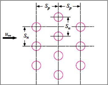
The Re number is calculated using the maximum velocity within the tube bank, defined as the velocity through the minimum flow cross-sectional area. This area, which is determined by the geometric arrangement of the tubes, as shown in Figure 8, is expressed as [20, 21]:
$u_{\max }=\frac{u_{\infty} \frac{S_n}{2}}{\left[\left(\frac{S_n}{2}\right)^2+S_p^2\right]^{1 / 2}-d}$ (9)
$R e=\frac{\rho u_{\max } d}{\mu}$ (10)
Figure 8. Schematic diagram of a staggered fin arrangement [22]
The total heat exchange area of a heat sink comprises both finned and unfinned surfaces and is calculated as:
$A_f=N_f p l$ (11)
where, for even greater precision for the ellipse, Ramanujan also proposed a more refined approximation, given as [23]:
$p \approx(a+b)\left[1+\frac{3 C}{10+\sqrt{4-3 C}}\right]$ (12)
and
$C=\frac{(a-b)^2}{(a+b)^2}$ (13)
$A_{u n f}=L \times W-N_f \pi a b$ (14)
Thus,
$A_t=A_f+A_{\text {unf }}$ (15)
For a fin with a circular cross-section, the $A_t$ is calculated as:
$A_f=N_f \pi d L$ (16)
$A_{u n f}=L \times W-N_f \frac{\pi}{4} d^2$ (17)
The present study examines the influence of fin geometry modification, specifically the transformation from a circular pin-fin heat sink to an elliptical pin-fin configuration, on the thermohydraulic performance of the system. The elliptical geometry was characterized by an aspect ratio (R) varying from 0.2 to 1.0 in increments of 0.2. Numerical simulations were performed using COMSOL Multiphysics under controlled boundary conditions at three constant surface temperatures (28 ℃, 53 ℃, and 83 ℃). To ensure the reliability of the numerical solution, we conducted an experimental investigation on an actual pin-fin heat sink. We measured parameters, including the surface temperature distribution and pressure drop across the heat sink, and compared them with the corresponding numerical predictions. The degree of agreement between the experimental and simulated results was used as a criterion to determine the appropriate mesh density. As a result, we optimized the number of mesh elements to achieve mesh-independent results while maintaining computational efficiency. The discussion section of the results is organized into the following parts:
5.1 Thermohydraulic characteristics
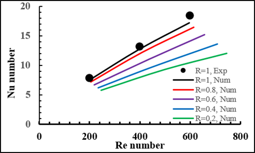
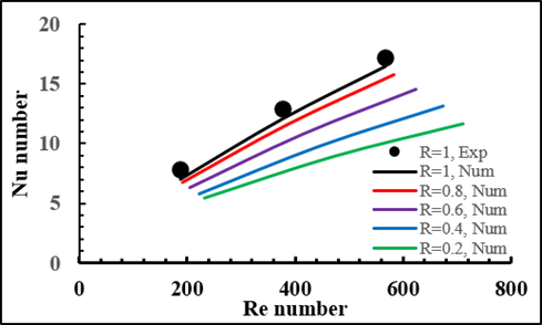
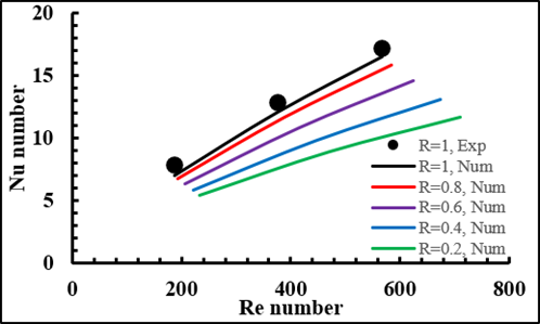
Figures 9–11 demonstrate the extent to which the Nusselt number depends on the Reynolds number at heat fluxes q1–q3. In all instances, the Nusselt number increased with Reynolds number: higher airflow velocities enhanced forced convection, decreased the thermal boundary-layer thickness, and promoted convective heat transfer from the fin surfaces. In turn, the Nusselt number increased (R = 1) from around 7.39 to 17.19 for the circular pin-fin configuration as the Reynolds number increased from 198 to 596.5. We find a comparable trend for q2 and q3, which corresponds to the highest Nusselt numbers at the greatest Reynolds numbers around 16.51 and 17.20, respectively. The effect of fin aspect ratio on thermal performance was demonstrated clearly. A decrease in the Nusselt number was observed across all operating conditions at the R = 0.2 and R = 1.0 ratios. At q1 and at the maximal Reynolds number, Nu dropped from about 17.19 for the circular fin to approximately 12.03 for the elliptical fin at R = 0.2; the decrease is approximately 30%. Similarly, at q2 and q3, reductions were close to 29% and 30%, respectively. This behavior mainly results from elliptical fins having streamlined geometry in the region, which delays boundary-layer separation and weakens vortex formation behind the fins. Whereas the circular fins produced relatively stronger wake regions and larger turbulence intensity, improving local convective heat transfer, the latter also resulted in increased hydraulic losses. At higher aspect ratios, the influence of Reynolds number was more significant. This means that, at lower Reynolds numbers, the thermal boundary layer was still quite thick, limiting heat transfer response to geometric transitions throughout fin configurations. As Reynolds number increased, the stronger inertial effect around the circular fins led to a higher mixing intensity and accelerated thermal transport; thus, significant differences in Nu between circular and elliptical geometries occurred. The numerical predictions for the circular pin-fin heat sink were experimentally tested and confirmed to be satisfactory, with differences around 6%. The agreement confirmed that the heat sinks studied by the numerical model have predicted the specific performance with high accuracy%.
Figure 9. Variation of Nu number versus Re number for different fin shapes at q1
Figure 10. Variation of Nu number versus Re number for different fin shapes at q2
Figure 11. Variation of Nu number versus Re number for different fin shapes at q3
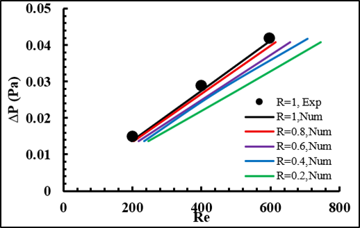
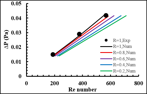
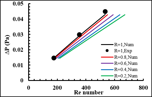
The difference between the pressure drop and the Reynolds number with respect to different fin aspect ratios is given in Figures 12–14. As anticipated, pressure drop and Reynolds number values varied with the speed, owing to increased fluid momentum and wall shear stresses inside the fin array. At each fin configuration with a circular geometry, the pressure drop increased from about 0.014 Pa to 0.041–0.043 Pa as the Reynolds number increased from about 180–200 to 530–600. Although the aspect ratio varied with the thermal behaviour, reducing the aspect ratio from R = 1.0 to R = 0.2 consistently decreased the pressure drop. At q1 and the largest Reynolds number, the pressure drop reduced from about 0.041 Pa for the circular fin to approximately 0.0407 Pa for the elliptical fin at R = 0.2. Similar decreases were observed for q2 and q3. While this decrease in size was moderate, the trend suggests that the elliptical configuration reduced the flow resistance by reducing the frontal area exposed to external flow and suppressing large wake formation behind the fins. The enhanced hydraulic response of elliptical fins results from their smooth profile, which reduces flow separation and recirculation zones downstream of the fins. On the other hand, circular fins serve as bluff bodies, which encourage earlier separation and even more intense vortex shedding, leading to an increase in form drag and pressure loss. Therefore, while the elliptical fins showed a slightly smaller Nusselt number, they delivered better hydrothermal efficiency; thus, the decrease in pumping power compensated for the reduction in thermal performance. Overall, we observe that there is a clear thermo-hydraulic tradeoff between circular and elliptical fin geometries. Both circular fins allow better heat transfer improvements due to stronger turbulence generation, and elliptical fins induce less hydraulic losses and better flow recovery. Thus, elliptical fins with moderate aspect ratios are an acceptable compromise between thermal and pressure drop effects in compact heat-sink applications.
Figure 12. Variation of ∆P versus Re number for different fin shapes at q1
5.2 Description of the numerical simulation
These contours are the temperature, velocity, and pressure profiles of the heat sink under different heat fluxes (q1–q3), inlet airflow velocities (u1–u3), and fin aspect ratios (R = 0.2–1.0). The plot analysis indicates that the thermal–hydraulic conductivity of the heat sink depends significantly on the Reynolds number and fin geometry. Contrasting the qualitative interpretation discussed in the previous section, numerical trends are used in the discussion to explain how fin aspect ratio is related to heat transfer and flow characteristics.
Figure 13. Variation of ∆P versus Re number for different fin shapes at q2
Figure 14. Variation of ∆P versus Re number for different fin shapes at q3
5.2.1 Temperature contours
The temperature contours in Figure 15 show that increasing Reynolds number increases the heat removal from the heat sink surface remarkably. Under low airflow velocity (u1), considerable regions of high temperature formed downstream of the fins owing to poor convective transport and thick thermal boundary layers. In these conditions, the circular fin shape (R = 1) resulted in increased local mixing, which decreased the thermal wake compared to the strongly elliptical fin shapes. From a quantitative perspective, the Nusselt number for the circular fin increased generally between 7.39 and 17.19 depending on the heat-flux level, while the value for the elliptical fin (R = 0.2) was close to 5.75 to 12.03. This results in an average reduction of the heat-transfer performance of around 25–30% when the geometry changes from a circular shape to a highly elliptical shape. The elliptical fins resulted in greater thermal wakes and larger temperature regions in between the fins at low Reynolds numbers because the reduced vortex strength and fluid mixing were compromised by the streamlined profile of the fins. Although lower turbulence intensity reduced the convective heat transfer to some extent, the temperature gradients parallel to the fin surfaces were smoother and more homogeneous with respect to the circular fins. By increasing the airflow speed from u1 to u3, the thermal boundary layer in all the configurations became thinner, and a lower surface temperature was obtained with better cooling uniformity. At the largest Reynolds number, the thermal field was greatly dictated by forced convection, and temperature differences between fin shapes decreased. However, the circular configuration has the most significant efficiency for heat transfer as the higher wake interaction improves the exchange of energy between the heated surface and airflow. For this purpose, increasing the heat flux from q1 to q3 enhanced the temperature gradients in the area around the heat sink. However, the increased airflow velocity mitigated this influence partially by increasing the removal of heat from the fin surfaces. The contour analysis also verifies that the fin aspect ratio has a strong influence on the thermal distribution in the heat sink. Lower aspect ratios expose less frontal surface to the airflow and weaken the recirculation regions behind the fins. While this decreases local heat-transfer coefficients, it reduces the localized hot spots and generates smoother temperature fields. While elliptical fins have more thermally stable distributions, circular fins have steeper thermal gradients correlated with more turbulence and wake.
5.2.2 Velocity contours
The velocity contours in Figure 16 demonstrate that the acceleration of airflow between neighboring fins increased appreciably with Reynolds number. There were thick viscous boundary layers and slow momentum transfer in the flow field at low inlet speed (u1). Bigger wake regions and more intense recirculation zones were created by circular fins since their blunt geometry led to early separation of the flow. Elliptical fins, in turn, induced a smoother cut in streamlines and smaller recirculation regions due to their smooth profile.
With an aspect ratio from R = 1.0 to R = 0.2, the flow separation behind the fins becomes weak, thus improving the recovery of flow and decreasing aerodynamic drag. This relationship is also considered to be consistent with the observed pressure drop behavior, where, in the case of circular fins, it ranged from an approximate pressure drop of 0.041–0.043 Pa, and it reduced to nearly 0.040–0.041 Pa for elliptical fins at the highest Reynolds number. While pressure loss was slightly less and the reduction of stress was minor, a better overall flow uniformity through the heat sink tubes was shown at the streamlined geometries. At intermediate and high-flow velocities (u2 and u3), flow acceleration between the fins increased, and the hydrodynamic boundary layer was thinner as well as local velocity was higher within the minimum value flow passages. The circular fins introduced more intense wake turbulence and flow motion that promoted convective thermal transfer but induced more flow resistance. By comparison, elliptical fins attenuated the amount of flow interference as well as created more stable profiles throughout the heat sink areas. The numerical findings further reveal more fin geometry impact; the higher Reynolds number seems to be the influence. Viscous effects in the flow field prevailed at low Reynolds numbers, and differences between fin arrangements were minimized. However, as the Reynolds number increased, there was more inertial action that induced more wake interaction and turbulence around circular fins. This accounts for the significantly higher difference in Nusselt number between circular and elliptical geometries at high flow conditions. In contrast, conical fins facilitate a smoother stagnation distribution, resulting in smaller pressure imbalances and narrower wakes. Increasing R reduces adverse gradients, enhances uniformity, and mitigates recirculation. At moderate velocities, stagnation pressure rises but recovers efficiently, with conical fins exhibiting the smallest downstream deficits. At high velocities, strong jetting reduces drag, narrowing geometric differences, although conical fins remain superior. Heat flux primarily modifies the pressure field at low velocities, where buoyancy decreases local pressure and increases asymmetry, particularly for truncated fins, while conical fins maintain smoother gradients. At higher velocities, the effect of heat flux is negligible. Overall, the contour analyses confirm that higher R factors improve velocity uniformity, temperature distribution, and pressure recovery, with conical fins consistently achieving the best balance between heat transfer enhancement and hydraulic efficiency.
5.2.3 Pressure contours
The pressure distribution around the fin arrays at different operating conditions is given in Figure 17. The pressure contour curves ensure that the highest pressures appeared in the front stagnation zones of the fins and were followed by lower pressures downstream in the wake sections. With the bluff geometry leading to more flow blocking and vortex shedding, circular fins generated bigger stagnation regions and stronger pressure gradients. The circular fin configuration generated the most pressure drop when it was used at the highest Reynolds number, approximately 0.041–0.043 Pa, according to the heat-flux mode. In contrast, the elliptical fins with R = 0.2 reduced the pressure drop to ∼0.040–0.041 Pa, although it seems relatively small in size since form drag and recirculation intensity are reduced through the relatively streamlined geometry. The pressure contours also show that reducing the aspect ratio improves pressure recovery downstream of the fins. Elliptical fins created narrower low-pressure wakes and smoother pressure gradients compared to the circular fins. Such behavior is attributed to lag time in flow separation and fewer wake-touch interaction rates between neighbouring fins. The elliptical configurations therefore had a lower power outflow to ensure a similar rate of airflow across the heat sink. The pressure gradients increased for all the fin geometries at significantly increased airflow velocity since the increased flow momentum and inertial forces enhanced the fluid momentum and inertial forces exerted. However, the relative differences of the fin configurations did not significantly change. The highest flow resistance was further maintained for circular fins, and the best hydraulic behaviour was achieved by elliptical fins. In general, the fin contour analysis results validate the thermo-hydraulic tradeoff between circular and elliptical fin configurations. Circular fins have better heat transfer because of strong turbulence generation and wake interaction, which leads to higher Nusselt numbers. But this has caused more pressure losses and higher flow resistance. In fact, elliptical fins minimize wake strength and enhance flow recovery, which reduces pressure drop, increasing hydrothermal efficiency. Consequently, elliptical fin configurations, especially at intermediate aspect ratios, are a good compromise between thermal and hydraulic performance optimizations for small heat sink applications.
(a) Temperature contours at q1 and u1
(b) Temperature contours at q1 and u2
(c) Temperature contours at q1 and u3
(d) Temperature contours at q2 and u1
(e) Temperature contours at q2 and u2
(f) Temperature contours at q2 and u3
(g) Temperature contours at q3 and u1
(h) Temperature contours at q3 and u2
(i) Temperature contours at q3 and u3
Figure 15. Temperature contours of the heat sink with different fin geometries under varying heat fluxes and airflow velocities
(a) Velocity contours at q1 and u1
(b) Velocity contours at q1 and u2
(c) Velocity contours at q1 and u3
(d) Velocity contours at q2 and u1
(e) Velocity contours at q2 and u2
(f) Velocity contours at q2 and u3
(g) Velocity contours at q3 and u1
(h) Velocity contours at q3 and u2
(i) Velocity contours at q3 and u3
Figure 16. Velocity contours of the heat sink with different fin geometries under varying heat fluxes and airflow velocities
(a) Pressure contours at q1 and u1
(b) Pressure contours at q1 and u2
(c) Pressure contours at q1 and u3
(d) Pressure contours at q2 and u1
(e) Pressure contours at q2 and u2
(f) Pressure contours at q2 and u3
(g) Pressure contours at q3 and u1
(h) Pressure contours at q3 and u2
(i) Pressure contours at q3 and u3
Figure 17. Pressure contours of the heat sink with different fin geometries under varying heat fluxes and airflow velocities
Based on this study, it was determined how fin geometry influences the thermo-hydraulic properties of pin-fin heat sinks and also concentrated on the phase transition from circular to elliptical profiles during the aspect ratio R = 0.2 to R = 1.0. In simulated numerical studies, validated experimentally, we found that interactions among vortex generation, boundary layer development, wake formation, and flow resistance control the heat sink's thermo-hydraulic properties. Circular fins yielded the largest Nusselt numbers, as the bluff-body geometry encouraged early boundary-layer separation, high vortex shedding, and turbulence intensity, which enhanced fluid mixing and local convective heat transfer. However, those mechanisms enhanced aerodynamic drag, pressure losses and pumping power. Conversely, elliptical fins showed delayed separation of the flow, smoother wake structures and improved pressure recovery owing to their streamlined geometry. While turbulence severity was mildly attenuated in the local heat transfer, a substantial reduction in flow resistance resulted in an improvement in the overall hydrothermal efficiency, as measured by the higher Nu/ΔP ratios. Contour analysis also revealed that the effect of fin geometry expanded at increased Reynolds numbers in the flow field, where inertial effects were dominant. At low airflow velocities, thicker thermal boundary layers and buoyancy-induced asymmetry intensified thermal gradients and broadened wake areas. However, higher velocities promoted thinner boundary layers, narrower wakes, and more uniform cooling distributions. Results explicitly show that maximizing heat transfer in isolation is not necessary for optimal heatsink design, as increased hydraulic penalties are often associated with thermal enhancement. Thermal enhancement needs to be coupled with pressure-drop reduction to perform well. Hence, elliptical fin arrangements, especially at a moderate aspect ratio, represent a compromise in terms of practical heat transfer response and hydraulic efficiency. Such results provide important design direction for the development of small, energy-saving heat sinks suitable for advanced electronics cooling and industrial type of thermal management.
|
a |
minor diameter, m |
|
Af |
Fin area, m2 |
|
As |
Lateral surface area, m2 |
|
At |
Total area, m2 |
|
Aunf |
|
|
b |
Major diameter, m |
|
cp |
Specific heat, J/kg‧℃ |
|
d |
Hydraulic diameter, m |
|
$\vec{g}$ |
Gravitational acceleration vector, -9.81 $\hat{J}$ m/s2 |
|
kf |
Thermal conductivity of the fluid, W/m‧℃ |
|
ks |
Thermal conductivity of solids, W/m‧℃ |
|
h |
Convection heat transfer coefficient, W/m2‧℃ |
|
H |
Out length of the heat sink, m |
|
l |
Fin length, m |
|
Sp |
Longitudinal pitch, m |
|
T |
Temperature, ℃ |
|
Ta,i |
Inlet air temperature, ℃ |
|
Ta,o |
Outlet air temperature, ℃ |
|
T |
Wall temperature, ℃ |
|
u |
Velocity in the x-axis coordinate, m/s |
|
u∞ |
Free stream velocity, m/s |
|
v |
Velocity in the y-axis coordinate, m/s |
|
$\dot{V}$ |
Volumetric flow rate, m3/s |
|
$\bar{V}$ |
Velocity vector, m/s |
|
w |
Velocity in the z-axis coordinate, m/s |
|
x, y, z |
Cartesian coordinates |
|
∇ |
Operator |
|
Nu |
Nusselt number |
|
Re |
Reynolds number |
|
ρ |
Density, kg/m3 |
|
μ |
Dynamic viscosity, kg/m‧s |
[1] Rahman, M.A., Hasnain, S.M.M., Paramasivam, P., Ayanie, A.G. (2024). Advancing thermal management in electronics: A review of innovative heat sink designs and optimization techniques. RSC Advances, 14(43): 31291-31319. https://doi.org/10.1039/D4RA05845C
[2] Li, J.N., Yang, L. (2023). Recent development of heat sink and related design methods. Energies, 16(20): 7133. https://doi.org/10.3390/en16207133
[3] Abbas, E.F. (2024). An overview of heat sink technology. International Journal of Applied Mechanics and Engineering, 29(4): 1-23. https://doi.org/10.59441/ijame/192127
[4] Deshmukh, P.A., Warkhedkar, R.M. (2013). Thermal performance of elliptical pin fin heat sink under combined natural and forced convection. Experimental Thermal and Fluid Science, 50: 61-68. https://doi.org/10.1016/J.EXPTHERMFLUSCI.2013.05.005
[5] Baruah, M., Borah, M., Das, H.K. (2016). The effect of major and minor axis of elliptical shape pin fin on heat transfer and pressure drop characteristics. IUP Journal of Mechanical Engineering, 9(2): 20-36. https://papers.ssrn.com/sol3/papers.cfm?abstract_id=2882473.
[6] Bahiraei, M., Mazaheri, N., Daneshyar, M.R. (2021). Employing elliptical pin-fins and nanofluid within a heat sink for cooling of electronic chips regarding energy efficiency perspective. Applied Thermal Engineering, 183: 116159. https://doi.org/10.1016/J.APPLTHERMALENG.2020.116159
[7] Kewalramani, G.V., Hedau, G., Saha, K.S., Agrawal, A. (2020). Effect of short pin fin with different shapes and arrangements on thermal resistance of micro heat sink. Journal of Enhanced Heat Transfer, 27(6): 491-503. https://doi.org/10.1615/JEnhHeatTransf.2020034367
[8] Pallikonda, M., Kupireddi, K.K., Balasubramanian, K., Chandramohan, V.P., Lee, P.S., Kong, C.C. (2021). Heat transfer enhancement using elliptical fin microchannel. Asia-Pacific Journal of Chemical Engineering, 16(6): e2712. https://doi.org/10.1002/apj.2712
[9] Ateş, A., Benam, B.P., Yağcı, V., Malyemez, M.C., Parlak, M., Sadaghiani, A.K., Koşar, A. (2022). On the effect of elliptical pin Fins, distribution pin Fins, and tip clearance on the performance of heat sinks in flow boiling. Applied Thermal Engineering, 212: 118648. https://doi.org/10.1016/J.APPLTHERMALENG.2022.118648
[10] Yu, T.F., Feng, Z.L., Zhang, Y., Xu, X.F., Xu, M. (2022). Numerical study on the thermal performance of microchannel heat sink with composite elliptical pin fin. Heat Transfer Research, 53(1): 61-81. https://doi.org/10.1615/HeatTransRes.2021039878
[11] Ali, N., Srivastava, S., Haque, I., Yadav, J., Alam, T., Siddiqui, T.U., Siddiqui, M.I.H., Cuce, E. (2024). Heat dissipation and fluid flow in micro-channel heat sink equipped with semi-elliptical pin-fin structures: A numerical study. International Communications in Heat and Mass Transfer, 155: 107492. https://doi.org/10.1016/J.ICHEATMASSTRANSFER.2024.107492
[12] Chahrour, K.M., Omran, I.H. (2025). Numerical investigation of twisted elliptical pin-fin heat sinks with varying perforation levels for enhanced hydrothermal performance. https://doi.org/10.2139/ssrn.5339774
[13] Abdulsahib, A.D., Alkhafaji, D., Albayati, I.M. (2025). A comprehensive review of the influence of various parameters on convection in different enclosures and heat sinks. Journal of Thermal Analysis and Calorimetry, 150: 3091-3119. https://doi.org/10.1007/s10973-025-14008-y
[14] Gijoy, S., Gayathri, M.A., Rejin, S., Roy, K.E.R. (2025). Numerical investigation and optimization of an asymmetric elliptical-cylindrical pin fin heat sink. International Journal of Thermal Sciences, 209: 109514. https://doi.org/10.1016/J.IJTHERMALSCI.2024.109514
[15] Danışmaz, M. (2025). Geometric analysis of pin fin heat sinks: Effects of ellipticity and perforation for fin on heat transfer. Case Studies in Thermal Engineering, 74: 106918. https://doi.org/10.1016/J.CSITE.2025.106918
[16] Chin, S.B., Foo, J.J., Lai, Y.L., Yong, T.K.K. (2013). Forced convective heat transfer enhancement with perforated pin fins. Heat and Mass Transfer, 49: 1447-1458. https://doi.org/10.1007/s00231-013-1186-z
[17] Souida, S., Sahel, D., Ameur, H., Yousfi, A. (2022). Numerical simulation of heat transfer behaviors in conical pin fins heat sinks. Acta Mechanica Slovaca, 26(3): 32-41. https://doi.org/10.21496/ams.2023.002
[18] Haque, M.R., Hridi, T.J., Haque, M.M. (2022). CFD studies on thermal performance augmentation of heat sink using perforated twisted, and grooved pin fins. International Journal of Thermal Sciences, 182: 107832. https://doi.org/10.1016/j.ijthermalsci.2022.107832
[19] Sadi, T., Sijan, S.R., Shifat, F.H.M., Haque, M.R., Harun-Or-Rashid, M. (2024). Numerical investigation of the effect of perforated almond, tunnel, and bishop-shaped pin fin heat sinks on the hydrothermal performance enhancement. International Journal of Thermofluids, 23: 100727. https://doi.org/10.1016/J.IJFT.2024.100727
[20] Beale, S.B. (2011). Tube banks, crossflow over. In Thermopedia. Begel House Inc. https://doi.org/10.1615/atoz.t.tube_banks_crossflow_over
[21] Žukauskas, A. (1972). Heat transfer from tubes in crossflow. Advances in Heat Transfer, 8: 93-160. https://doi.org/10.1016/S0065-2717(08)70038-8
[22] Holman, J.P. (2010) Heat Transfer. 10th Edition. McGraw-Hill, New York. https://www.scirp.org/reference/referencespapers?referenceid=2841294.
[23] Abramowitz, M., Stegun, I.A., Miller, D. (1965). Handbook of mathematical functions with formulas, graphs and mathematical tables (National Bureau of Standards applied mathematics series No. 55). Journal of Applied Mechanics, 32(1): 239. https://doi.org/10.1115/1.3625776