Hussien Aziz Saheb*![]() | Ahmed Kadhim Hussein
| Ahmed Kadhim Hussein![]()
© 2026 The authors. This article is published by IIETA and is licensed under the CC BY 4.0 license (http://creativecommons.org/licenses/by/4.0/).
OPEN ACCESS
In this numerical study, steady-state and laminar natural convection in an isosceles triangular cavity was studied. This study was 2D, and the FEM was used to solve the governing equations. The cavity was differentially heated, with the right wall hot and the left wall cold, while the base of the cavity remained adiabatic. The effect of different Rayleigh numbers (Ra) (103–107) on the heat transfer rate was studied. The effect of the presence of a T-shaped obstacle on the flow and heat transfer inside the cavity was studied. The results of this study showed that the heat transfer improves with increasing Rayleigh number for cases (I and II) with and without an obstacle. However, the Nusselt number (Nu) increased more in the absence of an obstacle. This study demonstrated the importance of obstacles in dividing the cavity space into more than one thermal zone, controlling fluid routing, and heat transfer. These results contribute to guiding the design of integrated thermal systems and nanofluid-based heat exchangers to improve heat transfer in engineering applications. These studies help improve the design of inclined thermal chambers used in passive cooling systems and static heat exchangers, enhancing Heat transfer behavior performance without the need for external operating power.
natural convection, triangular cavity, obstacle, nanofluid, 2D
The field of fluid flow and natural convection (NC) within cavities has witnessed increasing research interest recently, due to its diverse practical applications in many engineering systems [1-10]. This field has received extensive study through numerical simulations and laboratory experiments. The development of computer modeling and CFD techniques has contributed to the accurate and efficient analysis of the heat transfer (HT) behavior of complex domains. Recent research has covered a variety of cavity geometries, both classical and complex [11-17]. Research cases studied under various conditions showed a positive effect in improving the HT process. A set of different techniques was presented that proved effective in enhancing NC in cavities. These techniques involved modifications to the cavity shape or its inclination angle to enhance HT. Bairi [9] and Majdi et al. [18] employed various inclination angles of parallelogram cavities, inclined cubic cavities [19-21], and inclined trapezoidal cavities [22]. HT through cavities is enhanced by inserting fins into them [3]. Ma et al. [23] implemented a square fin within a cavity to enhance HT. Other studies varied in the choice of fin shapes and locations. Charazed and Samir [24] used a rectangular fin, and Saeid [25] proposed a variety of shapes, including a rectangular fin, a single triangular fin, a pair of opposing triangular fins, and a pair of isosceles triangular fins. The nature of these fins ranged from solid to porous. As shown by Asl et al. [26], in addition, Siavashi et al. [27] incorporated a network of porous fins within the cavity into their design. Many studies have shown that modifying the properties of a thermal fluid by changing (Ra) values is an effective means of enhancing NC [28-31]. Magnetic field is an effective means of controlling the rate of HT within cavities [14, 32-34]. Some researchers relied on porous media as an additional means to enhance HT performance in cavities [35-37]. The present work investigated the NC of pure water (H2O) in a triangular cavity and the effect of a T-shaped obstacle inside the cavity. This study discussed the change in flow patterns and HT behavior inside the cavity.
More than one study and research has shed light on the inclination angles of the triangular cavities, and these have been observed in the research of Pop and Sun [38] and Mejri et al. [39]. Kamiyo et al. [40] found that with increasing (AR), the (Ra) increases. Afrand et al. [41] introduced that the radiation effect enhances the HT performance, while entropy is an accurate indicator for evaluating energy losses and guiding optimal thermal design. Rahman et al. [42] found that the 3D simulation was more accurate than the two-dimensional simulation for monitoring flow in triangular cavities. Chatterjee et al. [43] found that a small heater size led to stronger circulation, lower entropy generation, achieves highest Nu. flow obstruction, higher entropy generation occurs at a large heater and achieves a low Nu. Ziaur et al. [44] found that the corrugated base of the cavity improved HT by improving the flow of fluid and creating thermal vortices. V-corrugated wall geometry facilitates stronger thermal mixing at high Ra. Saha and Gu [45] studied the effect of the adiabatic baffle inside the cavity, long baffle has a negative effect on HT. Ghoben and Hussein [46] used cylinders inside the cavity to enhance NC due to the increase in turbulent flow. Double-aligned cylinders have a negative effect on the (Nu), while the best values of the (Nu) occur when double non-aligned cylinders are used. Jalili et al. [47] established that the cylindrical obstacles inside the cavity enhanced HT by enhancing fluid circulation and increasing surface area for HT, resulting in better HT performance. (three cylinders) demonstrated the best performance in terms of thermal spread and (Nu). Roshani et al. [48] used three obstacles (an inverted triangle, a square, and a rhombus). The study revealed that the highest efficiency was at sinusoidal heating and the inverted triangle. Inverted triangle enhancing vortex formation, while Sinusoidal heating improved HT performance by generating initial force and secondary vortices. Yaseen et al. [49] showed that increasing (Ra) intensifies convection and improves (Nu̅). Lower power-law index (n) values, representing stronger shear-thinning behavior, lead to higher Nu̅ due to reduced viscosity. Dogonchi et al. [50] concluded that NC increases with a decrease in the radius of the base of the cavity. Bondareva et al. [51] examined the effect of an opening in a triangular cavity on the (Nu) and found that the opening facilitates the entry of cold stream and the exit of hot stream, thus enhancing NC. Rahman [52] concluded that HT decreases with a magnetic field in a triangular cavity. Increasing φ improved HT [53]. Thermal radiation directed at a nanofluid in a triangular porous cavity enhanced the HT [54]. Sarlak et al. [55] investigated the effect of the length of the heat source, which is the basis for generating convection for a nanofluid in a t cavity. The length of source enhanced HT [56]. The current numerical study is distinguished by a new innovation that was not addressed in previous studies, as it combined a complex geometric cavity, which is a triangle, and a complex obstacle in the shape of the letter T, which is an unconventional obstacle. This is something that was not addressed in previous studies, as this study analyzed the behavior of NC, the streamlines, and the isotherm. Therefore, this research aims to:
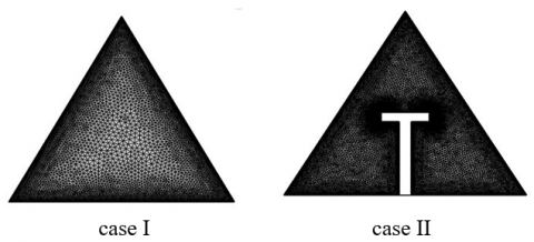
In this study, two cases of a triangular geometric cavity were numerically verified, as shown in the in Table 1. The first case in this study is called case I, and it is a triangular cavity without an obstacle. The second case is called case II, and it is a geometric cavity containing a T-shaped obstacle. Both cases have the same boundary conditions: a hot left wall and a cold right wall, while the cavity base is isolated. The water is the working water whose properties were numerically simulated in this study. Three different values of Ra (103–107) were applied. Pure water (H2O) is the working fluid, and its properties are shown in Table 2.
Table 1. Considered cases
|
Case |
Obstacle |
Ra |
|
I |
- |
103–107 |
|
II |
T |
103–107 |
Table 2. The physical properties [57]
|
ρ (Kg/m3) |
β (1/K) |
K (W/m‧K) |
Cp(J/Kg‧K) |
|
997.05 |
0.000210 |
0.6130 |
4179 |
Numerical solutions are an essential tool for studying three-dimensional NC within cavities of various geometric shapes. A set of governing equations is used according to the nature of the study, whether in steady-state or unsteady-state conditions. These equations include the continuity, momentum, and energy equations, which are utilized to describe HT and fluid motion within it. In this research, the general equations will be shown for a conventional fluid [58]. The assumption of this study is that the working fluid is pure water and that the flow is laminar, steady, incompressible, neglecting the effect of radiation and the generated heat, and adopting the Boussinesq approximation model.
3.1 Governing equations
The continuity equation [59]:
$\frac{\partial u}{\partial x}+\frac{\partial v}{\partial y}+\frac{\partial w}{\partial z}=0$ (1)
The momentum Eqs. (2), (3), and (4):
x-direction
$\begin{gathered}\frac{\partial u}{\partial t}+u \frac{\partial u}{\partial x}+v \frac{\partial u}{\partial y}+w \frac{\partial u}{\partial z}=-\frac{1}{\rho} \frac{\partial P}{\partial x}+v\left(\frac{\partial^2 u}{\partial x^2}+\frac{\partial^2 u}{\partial y^2}+\right. \left.\frac{\partial^2 u}{\partial z^2}\right)\end{gathered}$ (2)
y-direction
$\begin{gathered}\frac{\partial v}{\partial t}+u \frac{\partial v}{\partial x}+v \frac{\partial v}{\partial y}+w \frac{\partial v}{\partial z}=-\frac{1}{\rho} \frac{\partial P}{\partial y}+v\left(\frac{\partial^2 v}{\partial x^2}+\frac{\partial^2 v}{\partial y^2}+\right. \left.\frac{\partial^2 v}{\partial z^2}\right)\end{gathered}$ (3)
z-direction
$\begin{gathered}\frac{\partial w}{\partial t}+u \frac{\partial w}{\partial x}+v \frac{\partial w}{\partial y}+w \frac{\partial w}{\partial z}=-\frac{1}{\rho} \frac{\partial P}{\partial z}+v\left(\frac{\partial^2 w}{\partial x^2}+\frac{\partial^2 w}{\partial y^2}+\right. \left.\frac{\partial^2 w}{\partial z^2}\right)+\rho g \beta\left(T-T_c\right)\end{gathered}$ (4)
The energy equation:
$\frac{\partial T}{\partial t}+u \frac{\partial T}{\partial x}+v \frac{\partial T}{\partial y}+w \frac{\partial T}{\partial z}=\alpha\left(\frac{\partial^2 T}{\partial x^2}+\frac{\partial^2 T}{\partial y^2}+\frac{\partial^2 T}{\partial z^2}\right)$ (5)
The equations below are the governing non-dimensional equations.
$\begin{gathered}\mathrm{X}=\frac{x}{H} \quad \mathrm{Y}=\frac{y}{H} \quad Z=\frac{z}{H} \quad U=\frac{u H}{\alpha_{-} f} \quad V=\frac{v H}{\alpha_{-} f} \quad W=\frac{w H}{\alpha_{-} f} \\ P=\frac{p H^2}{\rho_f \alpha_f^2} \quad \theta=\frac{T-T_{r e f}}{T_H-T_C} T_{r e f}=\frac{T_C+T_H}{2} \quad R a=\frac{g \beta_f H^3\left(T_H-T_C\right)}{\vartheta_f \alpha_f} \\ P r=\frac{\vartheta_f}{\alpha_f}\end{gathered}$
The continuity equation:
$\frac{\partial U}{\partial X}+\frac{\partial V}{\partial Y}+\frac{\partial W}{\partial Z}=0$ (6)
The momentum Eqs. (7) and (8):
x-direction
$U \frac{\partial U}{\partial X}+v \frac{\partial U}{\partial Y}+w \frac{\partial U}{\partial Z}=-\frac{\partial U}{\partial X}+\operatorname{Pr}\left(\frac{\partial^2 U}{\partial X^2}+\frac{\partial^2 U}{\partial Y^2}+\frac{\partial^2 U}{\partial Z^2}\right)$ (7)
y-direction:
$\begin{gathered}U \frac{\partial V}{\partial X}+v \frac{\partial V}{\partial Y}+w \frac{\partial V}{\partial Z}=-\frac{\partial P}{\partial Y}+\operatorname{Pr}\left(\frac{\partial^2 V}{\partial X^2}+\frac{\partial^2 V}{\partial Y^2}+\right. \left.\frac{\partial^2 V}{\partial Z^2}\right)+\operatorname{RaPr} \theta\end{gathered}$ (8)
The energy equation:
$u \frac{\partial \theta}{\partial x}+v \frac{\partial \theta}{\partial y}+w \frac{\partial \theta}{\partial z}=\left(\frac{\partial^2 \theta}{\partial X^2}+\frac{\partial^2 \theta}{\partial Y^2}+\frac{\partial^2 \theta}{\partial Z^2}\right)$ (9)
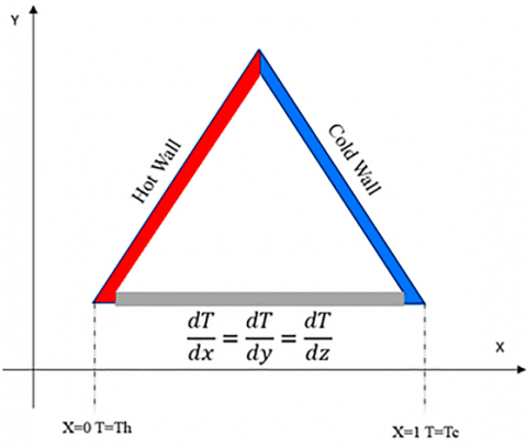
The boundary conditions and initial conditions shown below and in Figure 1 were applied for the purpose of solving the previous equations numerically. This study was carried out numerically in the COMSOL program, and it was a dimensionless study where the study considered the cold wall temperature TC and the hot wall temperature TH, so θ = 0 at the cold wall and θ = 1 at the hot wall. The purpose of conducting the study in a dimensionless manner is to transform it into a dimensionless field, and this simplifies the calculations and equations. Initial conditions for this study were: T = (Th + Tc)/2.
Hot wall at x = 0, T = Th, No slip (w = v = u = 0)
Cold wall at x = L, T = Tc, No slip (w = v = u = 0)
$\frac{\partial T}{\partial x}=\frac{\partial T}{\partial y}=\frac{\partial T}{\partial z}=0$ , No slip (w = v = u = 0)
Figure 1. The boundary conditions
The finite element method (FEM) was used to solve the governing equations of fluid flow and HT of steady-state NC of fluids (pure water) inside the triangular cavities described above. The network independence test was examined for two cases (one without an internal obstacle and the other with an internal obstacle) based on the stability of the (Nu). For case I, the network independence procedure is presented in Table 3, taking into account the error resulting from choosing the appropriate network. The adopted mesh for the cases (I II) is presented in Table 4 and Figure 2.
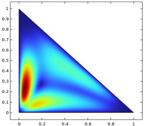
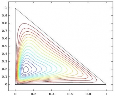
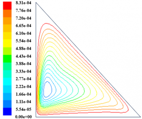
The validity of the streamline patterns and isotherms was also verified by comparing them with those presented by Triveni et al. [65] at (Ra = 106), as shown in Figure 3.
Figure 2. Mesh of geometry
Figure 3. The validation of the present data with Triveni et al. [60], Velocity contours (a) and stream function (b)
Table 3. The grid independence test at Ra = 103 for case I
|
Domain Elements |
Edge Element |
Nu |
|
4128 |
107 |
5.187 |
|
4318 |
112 |
5.213 |
|
5984 |
271 |
5.641 |
|
6002 |
279 |
5.801 |
|
6947 |
310 |
5.814 |
|
9836 |
341 |
5.818 |
Table 4. The selected grid for cases (I II)
|
Case |
Domain Elements |
Edge Element |
|
case I |
6947 |
310 |
|
case II |
11745 |
493 |
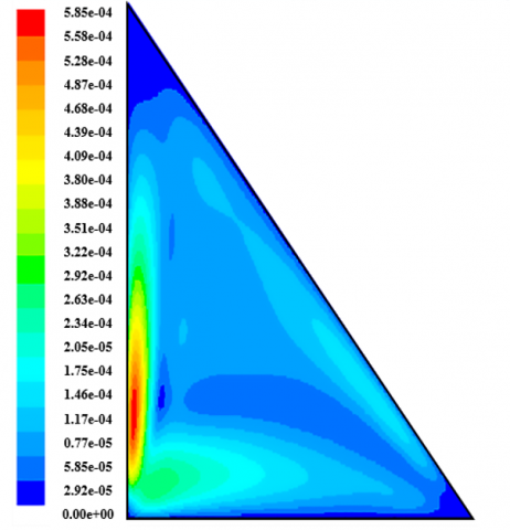
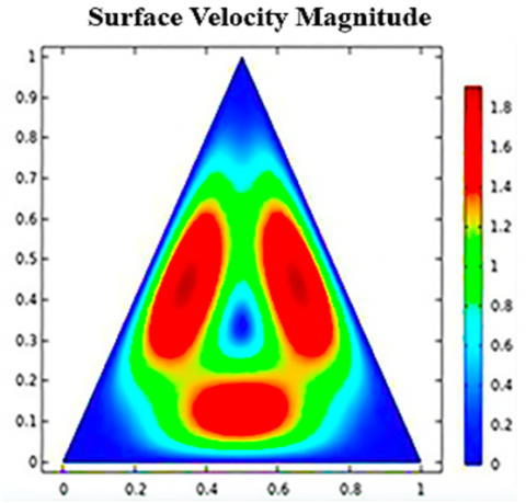
In the case I, an isosceles triangular cavity as in Figure 4(a) is studied, under conditions including a relatively low (Ra = 1000), where the right wall is cold, the left wall is hot, and the base is insulated. The flow distribution shows the emergence of a symmetrical pattern containing three thermal circulation cells within the cavity, with a concentrated velocity in the central region. The max velocity is 1.8, indicating moderate fluid movement despite the weak convection at Ra = 103. This behavior indicates that the flow is relatively coherent and provides moderate HT efficiency via the natural circulation mechanism within the cavity.
The velocity distribution shows the formation of thin boundary layers along the walls due to the reduced velocity near the surfaces, while high-speed internal vortices appear, enhancing mixing and HT. This behavior is consistent with the principles of boundary layer theory and vortex dynamics, where the boundary layer thickness and vortex intensity control the efficiency of HT within the triangular cavity.
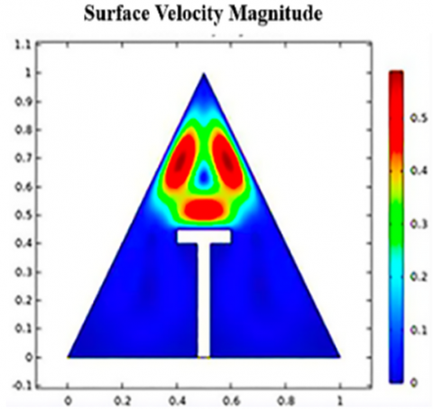
In Figure 4(b), case II, the cavity under the same boundary conditions contains a T- obstacle. This results in an unambiguous change in the flow pattern, with the lower region of the cavity becoming almost stationary, and only a single small rotation cell forming in the upper part. The max velocity also dropped significantly to about 0.5, indicating weak movement within the lower compartment. This change reflects that the T- obstacle slows the fluid flow and reduces the effectiveness of NC, as it divides the field into two regions: an active region with little flow at the top, and a nearly static region below the obstacle, resulting in a lower HT rate in the greater part of the cavity.
Figure 4. Velocity contours at Ra = 1000
Figure 4(b) shows that the presence of the T-shaped obstacle restricted flow down the cavity, resulting in the formation of thick, weakly moving boundary layers near the obstacle. In contrast, the effective flow is concentrated in the upper region in the form of confined vortices above the obstacle. This behavior reflects the obstacle's role in redistributing circulating currents and controlling boundary layer thickness. This behavior reflects the role of the obstacle in redistributing circulating currents and controlling the thickness of the boundary layer, consistent with the principles of boundary layer theory and vortex dynamics, where the resulting closed vortices enhance or impede convective mixing depending on their location.
This change reflects that the T- obstacle slows the fluid flow and reduces the effectiveness of NC, as it divides the field into two regions: An active region with little flow at the top, and a nearly static region below the obstacle, resulting in a lower HT rate in the greater part of the cavity. The above analysis shows that the triangular cavity without an obstacle performs better in HT by NC due to the smooth flow and free circulation of the fluid.
The T- obstacle reduces HT by obstructing fluid movement. However, it is useful in cases where flow must be directed to a specific area, heat loss must be reduced, or thermal separation between two areas within a cavity is required, giving it a vital role in thermal insulation or thermal control applications.
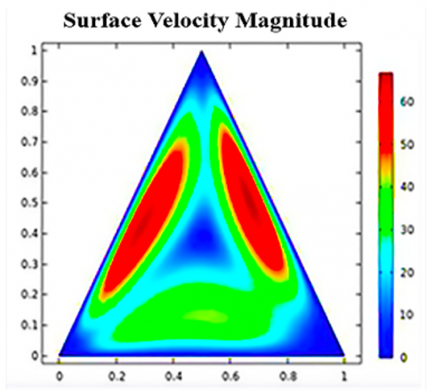
For case I, but at Ra = 105, as shown in Figure 5(a), a relatively strong thermal circulation pattern is formed, represented by two clear cells on both sides of the cavity. Max velocity reaches approximately 60, which expresses a clear activity in the fluid movement. In this case, NC begins to dominate the flow, resulting in an active thermal distribution that enhances the HT efficiency compared to cases at Ra = 103.
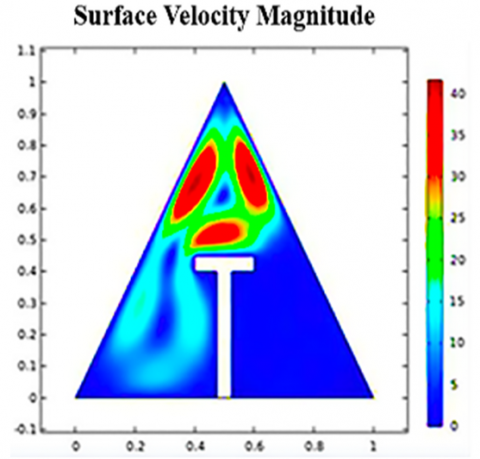
At the same Ra = 105, as shown in Figure 5(b) (case II), the T- obstacle concentrates the flow over the obstacle, forming a single active rotational cell, while the movement below the cavity decreases significantly, and the maximum velocity decreases to about 40. This means that the T- obstacle prevents the development of rotating cells and restricts HT towards the lower part, resulting in a decline in the active flow area and the formation of vortices confined to the upper part of the cavity, which weakens the convection efficiency compared to case I at Ra = 105. The flow is more diffuse and efficient in HT due to active NC, as is clearly demonstrated in Figure 5(a). In Figure 5(b), the flow is directed and limited in the upper part of the cavity and almost disappears in the lower regions, resulting in a decrease in overall HT performance. As the Ra increases, the flow becomes more sensitive to the presence of a T- obstacle within the cavity, which more clearly influences the pattern and distribution of the movement.
In Figure 5(a), the flow circulates freely within the cavity, generating thin boundary layers near the hot and cold walls with the appearance of two symmetrical vortices that enhance heat mixing and energy transfer. In Figure 5(b), the presence of the T- obstacle increased the thickness of the lower boundary layer and weakened the flow at the bottom, with the thin layers and vortices concentrated in the upper part. This change reflects the role of the obstacle in redistributing the boundary layers and controlling the dynamics of the vortices, which altered the HT mechanism and mixing efficiency compared to the case without the obstacle.
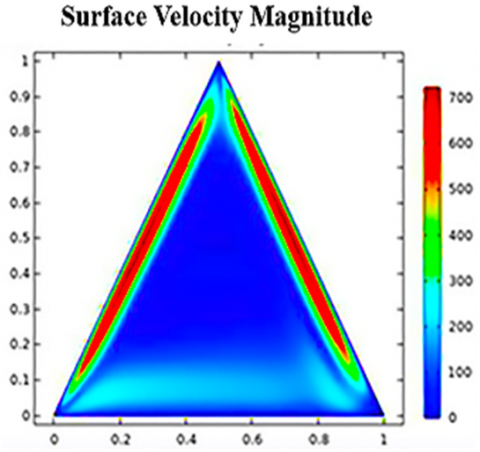
For case I at Ra = 10⁷, very thin flow layers (Boundary Layers) are observed, located near the side walls, and as shown in Figure 6(a), the maximum velocity reaches approximately 700, which indicates a strong and concentrated flow along the cavity walls. At high Ra, buoyancy forces are strong, and NC becomes the completely dominant mechanism. The fluid heats rapidly at the hot wall and rises along it, while it cools and descends along the cold wall, creating a strong, directed flow that enhances HT efficiency.
Figure 5. Velocity contours at Ra = 105
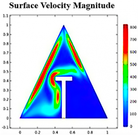
While for case II at Ra = 107 in Figure 6(b), despite the maximum velocity rising to over 700, it was concentrated near the edges and only above T- obstacle. This resulted in the formation of a large and complex vortex in the upper part of the cavity, while the area below the T- obstacle was almost devoid of any effective flow.
This suggests that the T- obstacle obstructed the natural flow path and forced the fluid to change direction, disrupting the flow pattern and heat distribution. As a result, the lower regions were virtually thermally isolated, reducing the efficiency of NC throughout the cavity. Figure 6(a) shows the strength and uniformity of the convection, which indicates a high efficiency in HT, as the water flows smoothly and freely within the space. In contrast, in Figure 6, the presence of a T- obstacle inhibits the flow path, causing local non-uniform vortices concentrated in the upper part, while the lower part suffers from weak HT.
Although the maximum velocity remains high in both cases (I, II) at Ra = 107, its distribution is broader and more widespread in the case of the obstacle -free cavity, enhancing the HT efficiency across the entire range.
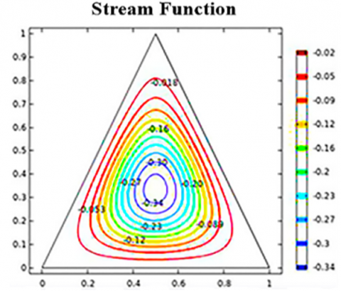
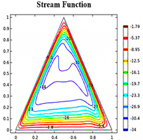
The stream function in Figure 7(a) case I, shows a uniform pattern centered in the cavity center, with a single circular rotation cell. The maximum value of the stream function is estimated to be around −0.34. This pattern indicates weak and slight fluid rotation, consistent with a low (Ra = 10³), where heat conduction dominates, with convection beginning to be minimal.
Figure 6. Velocity contours at Ra = 107
It is also noted that the flow is concentrated in the cavity center without disturbances or major deviations, and is more uniform and clearer.
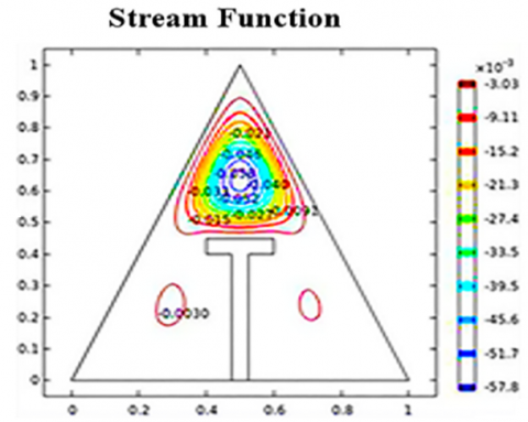
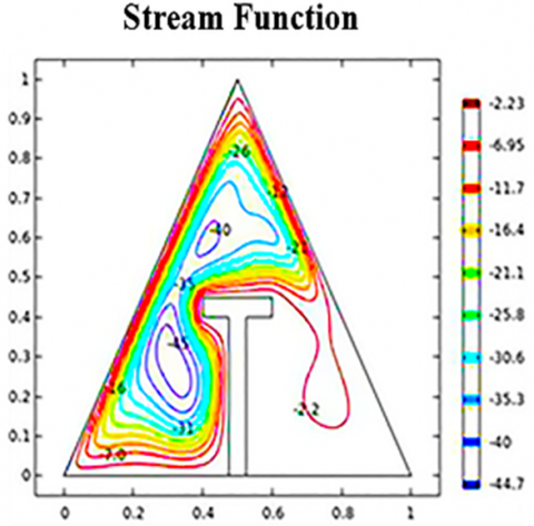
In Figure 7(b), which represents case II at a low Ra, the stream function shows a small, confined rotation cell in the upper part above the obstacle, while the lower regions of the cavity are virtually devoid of any rotation. The streamline’s maximum value drops markedly to around 10−2, indicating very weak fluid motion.
Analysis indicates that the obstacle interrupted and divided the natural flow path, resulting in very little flow and a state of near-stagnancy in most parts of the cavity, particularly in its lower half. The effect of NC is already weak at low Ra, but the presence of the obstacle exacerbates this weakness and hinders the development of effective thermal circulation.
Therefore, the barrier-free condition is better at low Ra values, as it allows for the formation of a uniform, albeit simple, circulation pattern, which enhances HT compared to case II at Ra = 103.
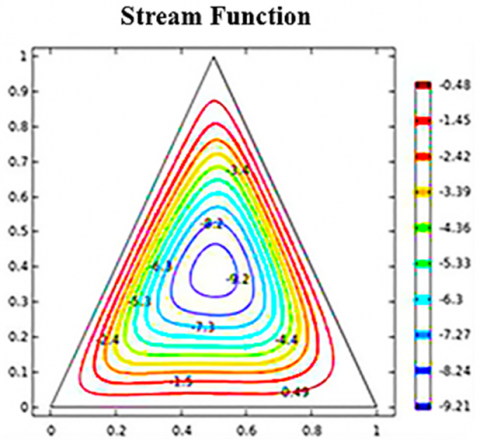
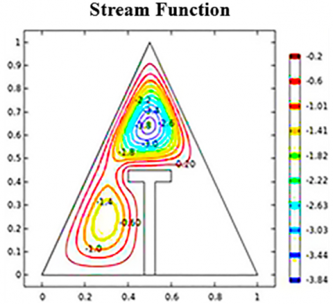
Figures 8(a) and 8(b) compare the stream function at Ra = 105. For case I, Figure 8(a) shows a single, uniform circulation cell covering the entire cavity, indicating relatively active convection and high HT efficiency. For case II, Figure 8(b) shows the presence of the internal obstruction causing the flow to split, forming a small circulation cell at the top of the cavity, with almost no flow at the bottom, reducing the efficiency of NC within the cavity.
Figure 7. Stream function at Ra = 1000
It is noted that without the obstruction inside the cavity, there was a large circulation cell centered in the center of the cavity, with maximum stream function values of approximately −9.2, indicating strong and advanced flow. The stream function is dense and uniform, reflecting the presence of efficient and smooth thermal circulation.
Compared to the case at Ra = 103, heat flow is significantly enhanced at Ra = 105, where NC becomes the dominant HT mechanism. Due to the absence of any internal obstructions, the fluid circulates freely within the space, improving the HT efficiency of the system.
Figure 8(b) shows two asymmetric circulation cells, one above the T- obstacle and a smaller, weaker one below, with the maximum value of the stream function decreasing to only about −3.0. The T- obstacle causes the flow path to meander and change direction, resulting in non-uniform flows and limited local vortices. This disruption of the natural flow path reduces the convection efficiency.
Figure 9(a) for case I at Ra = 107 shows the formation of strong flow cells extending along the walls, with minimum values of the stream function ranging from -34 to -40, indicating high-intensity circulation. An asymmetric double flow pattern is formed, and dense layers of lines are created near the side walls of the cavity, especially at the hot and cold walls.
This indicates that NC is at its peak, where the thermal and flow boundary layers are very active, and the organized and intense flow covers the entire space, achieving highly efficient HT within the cavity.
Figure 8. Stream function at Ra = 105
Figure 9(b) shows the formation of several complex flow cells (vortices), one in the upper right and another on the left, as a result of the obstacle's effect on the flow pattern. The maximum values of the stream function reach about −44, which is higher than in the case without an obstacle, indicating the presence of high local velocities.
However, the flow pattern appears non-uniform, with clear separation due to the obstacle. Analysis indicates that the obstacle creates flow turbulence, leading to multiple circulation paths and the formation of separate local vortices. This reduces the flow distribution efficiency despite high speeds and weakens the HT efficiency within the cavity compared to the unobstructed case.
Even though the maximum stream function values are higher in the presence of an obstacle, the flow pattern becomes turbulent and non-uniform, with the formation of discrete local vortices. On the other hand, a cavity without an obstacle provides a more stable and consistent flow, which contributes to enhanced HT efficiency.
T- obstacle results in the splitting of flow paths and the appearance of turbulence. While this can be beneficial in special applications that require enhancing mixing or reducing conductivity in specific areas, it generally degrades the overall HT performance within the cavity.
Figure 9. Stream function at Ra = 107
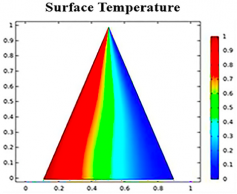
Figure 10(a) case I shows a uniform HT from the hot wall to the cold wall. A smooth color gradient is observed from red (high temperature) to blue (low), indicating a linear and uniform heat distribution. At low (Ra = 103), the effect of NC is very weak, and the conduction mechanism is dominant. Due to the absence of strong flow inside the cavity, no distortions are observed in the isotherms, making the HT mainly due to conduction rather than convection.
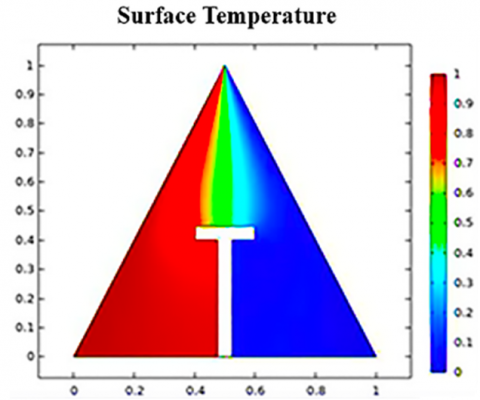
On the other hand, Figure 10(b) shows a clear distortion in the temperature distribution as a result of the presence of the obstacle, as the heat is largely concentrated in the area above the obstacle, while the sides remain relatively cold, and the area below the obstacle is almost thermally isolated.
The obstacle obstructs NC, preventing it from fully dispersing down the cavity, resulting in isolated areas within the space. This reduces conductivity efficiency, creating thermally static zones where inefficient HT occurs, thus impairing overall HT performance.
At low (Ra = 103), NC is almost ineffective, and conduction is the dominant HT mechanism. However, the presence of a T- obstacle exacerbates the weak HT, as it not only reduces the effect of convection but also prevents complete conduction across the space, resulting in partial thermal insulation.
Meanwhile, the case I exhibits a more uniform and continuous HT, making it the ideal choice under weak NC conditions.
The results show that the temperature gradient in the unobstructed case (Figure 10(a)) is uniform from the hot wall to the cold wall, with symmetrical thermal boundary layers forming along the walls, reflecting a stable HT. In the case of the presence of the obstacle (Figure 10(b)), the thickness of the thermal layer below the cavity increased as a result of the obstruction of flow, while the thermal changes were concentrated above the obstacle, which clarifies the role of the obstacle in reshaping the thermal boundary layer and changing the path of HT inside the cavity.
Figure 10. Temperature contours at Ra = 1000
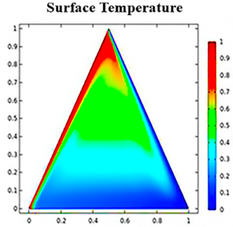
Figure 11(a) is similar to Figure 10(a), as it shows an asymmetrical heat distribution. As a result of the Ra rising to 105, the isothermal lines begin to bend due to the onset of the effect of NC. The upper left-hand region of the cavity appears hotter, reflecting upward HT due to fluid movement. NC begins to take effect, where conduction is not the sole dominant HT mechanism as in the lower cases. The flow within the cavity begins to transfer heat from the hot wall toward the top of the cavity, distorting the heat lines and creating an asymmetric heat distribution. This indicates the development of convection cells that have begun to form clearly within the cavity.
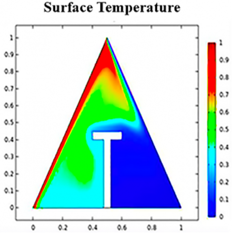
While Figure 11(b) shows a clear concentration of heat directly above the T- obstacle, the sides and bottom of the cavity remain relatively cool, indicating a heat distribution imbalance. The area below the baffle remains relatively thermally insulated, with weak HT to it. The presence of the obstruction prevents the development of circulating cells and impedes fluid movement within the cavity, resulting in NC being restricted to the upper portion and virtually absent in the lower half. This restriction results in a significant loss of overall HT efficiency.
Although the Ra, Ra = 105, represents the threshold for NC to dominate HT, the presence of an obstacle prevents this effect from being fully exploited. Conversely, in the absence of an obstacle, HT occurs smoothly by upward flow, resulting in a more uniform and efficient heat distribution within the cavity.
Figure 11. Temperature contours at Ra = 105
In Figure 11(a) (unobstructed), the thermal gradient is distributed obliquely within the cavity, with heat moving from the hot wall to the cold wall and a broad thermal boundary layer forming that extends across the entire cavity, indicating more diffuse thermal mixing. In Figure 11(b) (with a T- obstacle), the obstacle refocuses the thermal gradient at the top of the cavity, causing the thermal layer below to thicken and constrict convection to a narrow path above the obstacle. This demonstrates that the presence of the obstacle alters the structure of the thermal boundary layer and restricts convection paths, compared to the open case.
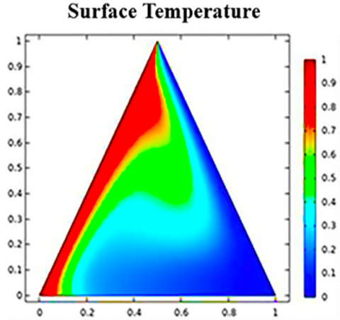
At a high Ra = 107, Figure 12(a) shows the surface temperature distribution, with intense HT near the hot wall of the cavity, where a sharp thermal gradient forms on the left-hand side. A clear asymmetry in the distribution is also observed, with the warm region rising on the left side and the cold region descending on the right side, indicating a strong and active heat flow pattern.
Figure 12. Temperature contours at Ra = 107
At very high (Ra = 107), NC is the dominant HT mechanism. Ultra-thin thermal layers form near the walls to increase the fluid velocity, which efficiently extracts heat from the hot wall and then rapidly redistributes it within the space. This is a clear indication of the high efficiency of convective HT in the absence of obstructions, as the buoyancy effect and thermal circulation within the cavity are maximized.
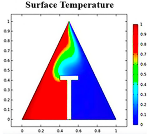
In Figure 12(b), it is noted that there is a strong thermal concentration directly above the T- obstacle, while the area below the T- obstacle remains in a state of near-static temperature, with a non-uniform color gradient and a clear discontinuity in the heat distribution across the cavity.
The T- obstacle interrupts the natural flow of fluid and prevents the formation of complete convection cells, resulting in the formation of localized thermal vortices limited only to the upper portion. This restriction impedes HT to the lower regions and results in a significant loss in heat exchange efficiency within the space. In Figure 12(a) (unobstructed), the thermal gradient appears to be distributed almost symmetrically along the walls, with thin thermal boundary layers close to the surfaces and a gradual gradient towards the center of the cavity, indicating more extensive HT. In Figure 12(b) (with T- obstacle), the presence of the obstacle led to a redistribution of heat, as it increased the thickness of the thermal layer below the obstacle and concentrated the thermal gradient region above it, which shows that the obstacle reshaped the thermal boundary layer and limited the convection paths compared to the case without an obstacle.
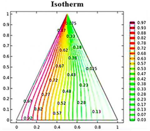
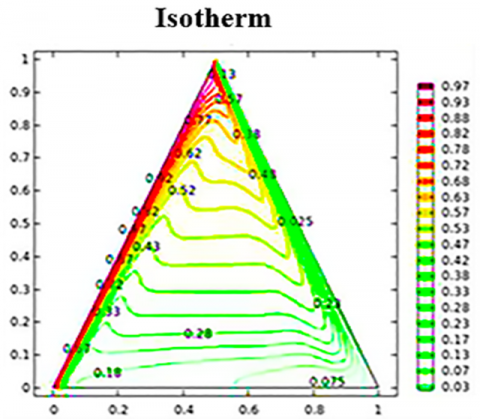
Figure 13(a) shows the isotherm maps with a uniform and almost straight pattern, with the lines moving from the hot wall to the cold wall vertically, with an equal and uniform temperature gradient across the space.
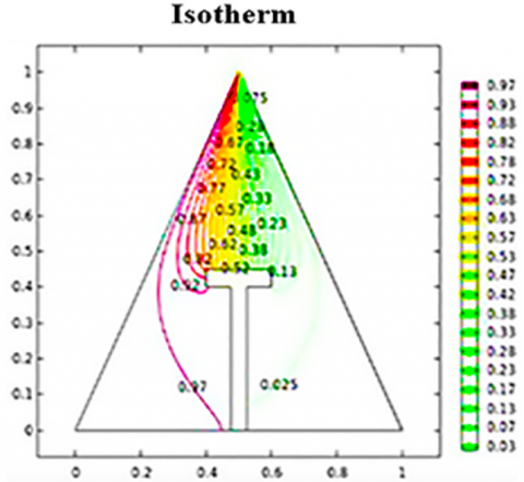
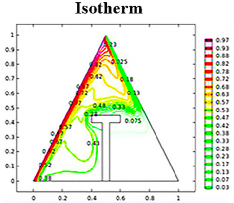
Figure 13. Isotherm contours at Ra = 1000
This distribution clearly indicates that conduction is the dominant mechanism of HT, with no significant influence from NC. The absence of bends or distortions in the lines reinforces this conclusion and is fully consistent with the low (Ra = 103), where buoyancy forces are insufficient to induce efficient fluid motion. Consequently, HT proceeds quietly through the medium, with no significant contribution from convection.
The isotherm maps show clear bends and non-uniform twisting in the thermal distribution due to the presence of the T- obstacle, as shown in Figure 13(b). The region below the obstacle appears as a thermally quasi-static area with quasi-closed isotherms, while the thermal gradient in the upper part above the obstacle stacks up.
The T- obstacle impedes HT even through conduction, as it cuts off the direct path between the hot and cold walls, causing heat to accumulate in a limited area and impairing conduction in other areas, especially below the T- obstacle.
Although Ra = 103 does not produce effective NC, the T- obstacle itself is the sole cause of the observed thermal distortion. Under these conditions, the heat distribution in the cavity without the obstacle is more uniform and consistent, making it a better choice from an engineering perspective for conductive HT in systems operating at low Ra numbers.
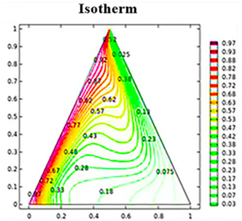
Figure 14(a) shows clear bends and openness of the isotherms in some areas, especially in the upper part of the cavity. The temperature gradient between the two walls is no longer symmetrical, as the lines bend upwards and become more convergent near the hot wall, reflecting an increase in the temperature gradient there.
This behavior indicates that NC is beginning to exert its influence alongside conduction, as the (Ra) increases to 105. The hot fluid begins to move upward within the cavity, distorting and bending the isotherms. This deflection of the isotherms indicates more active HT and reflects improved thermal efficiency compared to the low-Ra case, where conduction was the dominant mechanism.
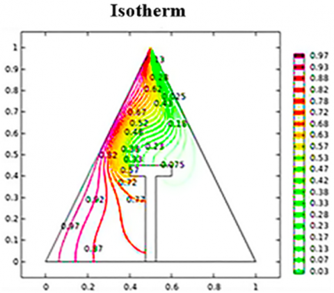
The isotherm lines exhibit non-uniform behavior, as in Figure 14(b), where they rise from the hot wall and then break or twist upon contact with the obstacle. A strong heat concentration is observed above the obstacle, as the lines are very close together, while the region below the obstacle shows horizontal or semi-closed lines, indicating thermal inactivity or isolation in that region.
The T- obstacle impedes convective HT from the hot wall to the rest of the cavity, preventing the formation of a complete thermal circulation cell. As a result, a small "heat bubble" forms at the top, and heat exchange becomes localized and limited. Overall, HT efficiency is reduced, as the lower regions remain almost thermally insulated.
At Ra = 105, NC begins to have a significant effect. In the case without an obstacle, the heat lines propagate freely throughout the cavity, enhancing heat exchange efficiency. In the case of an obstacle T, however, the heat lines are broken and confined to the upper part, weakening conduction to the rest of the cavity and significantly reducing overall thermal efficiency.
Figure 15(a) shows the isotherm maps showing a strong curvature, especially near the hot wall, with a sharp and clear temperature gradient within the boundary layer. The thermal distribution extends smoothly to cover the entire cavity area, without interruption or inert regions.
At very high (Ra = 107), NC becomes the dominant HT mechanism. This results in significant distortion of the heat lines due to the rapid and active flow of the fluid, causing very thin thermal layers to form near the hot and cold walls. This pattern reflects a great efficiency in extracting heat from the hot source and distributing it throughout the entire space, making this case a clear example of highly efficient HT without any internal obstructions.
In Figure 15(b), the isotherms show significant and non-uniform distortion, especially in the obstacle region. The thermal gradient is concentrated in the upper part only, while the lower part of the cavity appears thermally inert, with dead or nearly horizontal lines that do not show effective thermal activity.
Figure 14. Isotherm contours at Ra = 105
Figure 15. Isotherm contours at Ra = 107
The T- obstacle impedes fluid flow and interrupts the NC path, resulting in poor heat distribution, even at very high (Ra = 107). Local thermal vortices form, isolating some of the heat in the upper region and preventing it from reaching the lower region, reducing HT efficiency.
At Ra = 107, NC is assumed to achieve maximum efficiency, which is achieved in the case of a cavity without a baffle due to uniform flow and a wide thermal distribution. However, in the case of a baffle (T), thermal performance deteriorates due to discontinuities and distortions in the distribution, making the case without a baffle the best in terms of thermal efficiency and the benefit of strong NC.
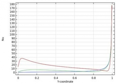
Figures 16 and 17 represent a graphic comparison of the local (Nu) along the hot wall inside a triangular cavity, in two cases: the first without an internal obstacle (I), and the second with a T- obstacle (II). In the case I (without obstacle), the Nu starts at an intermediate value at the base of the wall, then decreases slightly in the central region, and rises sharply near the upper edge of the hot wall at Y = (1). The three curves show a clear effect of the variation of the (Ra), and it is noted that the highest value of the (Nu) reaches about 170 at the top of the wall. This indicates the presence of a thin thermal layer and very efficient HT at that point due to the natural pooling of the up flow.
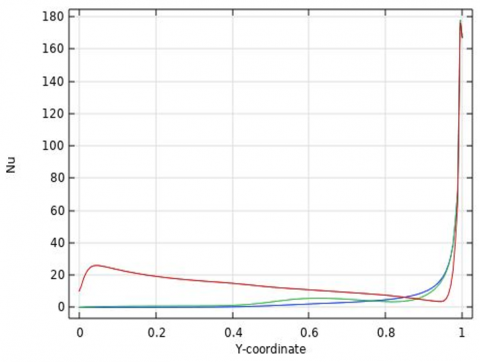
In case II, the general pattern appears similar in terms of the direction of the curve, but there is a difference in the details. Although the Nu continues to rise in the upper region, the values in the middle of the wall appear flatter, indicating a slowdown or relative weakness in HT in that region. This is due to the obstacle effect, which hinders the development of ideal flow and reduces the effectiveness of convection in the medium, while maintaining active heat exchange at the top.
In general, the figure shows that the local (Nu) is affected by the presence of an obstacle, particularly in the mid-hot wall regions, where HT is weaker than in the open case. Although the highest HT remains at the top due to the concentration of upward flow, the obstacle-less cavity achieves a more uniform and efficient HT distribution along the entire hot wall.
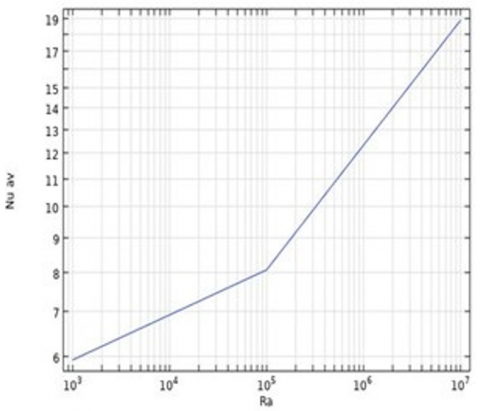
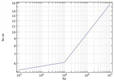
Figures 18 and 19 show a comparison between the curves of the average Nusselt number (Nuavg) as a function of the (Ra) inside a triangular cavity, in two cases (I, II).
Figure 16. Nu distribution along the hot wall for case I
Figure 17. Nu distribution along the hot wall for case II
Figure 18. The Nu versus Ra for case I
Figure 19. The Nu versus Ra for case II
Quantitative analysis shows that Nusselt values increase with increasing Ra in both cases, reflecting the increased effect of NC, but with a marked difference in efficiency. In case I, the value starts at around 6.1 at Ra = 103 and reaches 19 at Ra = 107, indicating a significant improvement in heat exchange. In contrast with case II, the values are lower at each point, starting at 5.2 and only reaching 15.5 at the same high Ra value.
It is concluded that the obstacle restricts fluid movement and impairs the development of NC cells, resulting in reduced HT efficiency, especially at high Ra values. At low Ra values, where conduction dominates, the difference between the two cases is minimal. Overall, the data show that the cavity without an obstacle achieves better thermal performance and more efficient HT distribution, especially under strong NC conditions.
• Obstacles within cavities redirect flow and are therefore important in systems that require precise directional flow control.
• Obstacles create internal isolation zones and are thus used to reduce cooling or heating in specific areas.
• The Obstacle within a cavity prevents the formation of large vortices or excessive thermal fluctuations and thus enhances the reliability of delicate thermal systems (such as electronic components).
• Internal obstacles contribute to creating multiple thermal environments within a single space, as they separate the field into more than one thermal zone. This is of great importance in heat exchangers and multi-functional systems.
• Obstacles have a positive role despite the low HT efficiency, as their presence allows heating of a specific area within the cavity and not others, and they also play a prominent role in directing heat.
• The role of obstacles is highlighted in biological and medical devices that contain sensitive areas that should not be heated.
• At low (Ra = 103), the thermal behavior of both cases is similar due to weak convection.
• At intermediate (Ra = 105), a clear difference in thermal behavior appears, and convection begins to dominate.
• Thermal convection is at its peak and dominates the entire space, and a radical difference in thermal behavior within the cavity is evident at high (Ra = 107).
• T-shaped Obstacles within triangular cavities reduce efficiency but are useful for thermal insulation or thermal guidance applications, depending on design requirements.
• Obstacle work inversely to the (Ra), i.e., as the (Ra) increases, the Obstacle reduces the NC, making the tank without a baffle more efficient in transferring heat.
Considering that this study assumes a 2D, steady state, which may limit its representation of the true 3D flow behavior, it is recommended that the study be expanded to an unsteady 3D model and the effects of different types of fluids and obstacles be investigated in the future.
|
Cp |
Specific heat at constant pressure, J/Kg‧K |
|
C |
Location of the partition, m |
|
G |
Acceleration due to gravity, m/s2 |
|
Ha |
Hartmann number |
|
H |
Height of partition, m |
|
K |
Thermal conductivity, W/m. K |
|
Nu |
Nusselt number |
|
P |
Pressure, N/m2 |
|
Pr |
Prandtl number |
|
Ra |
Rayleigh number |
|
T |
Temperature, K |
|
t |
Time, s |
|
U |
The velocity component in x-direction, m/s |
|
V |
The velocity component in y-direction, m/s |
|
W |
The velocity component in z-direction, m/s |
|
X |
The coordinate in horizontal direction, m |
|
Y |
The coordinate in vertical direction, m |
|
Z |
The coordinate in axial direction, m |
|
Greek symbols |
|
|
α |
Thermal diffusivity, m2/s |
|
β |
Coefficient of thermal expansion, 1/K |
|
γ |
Inclination angle of the magnetic field, ° |
|
μ |
Dynamic viscosity, Kg/m.s |
|
ρ |
Density, Kg/m3 |
|
φ |
Nanoparticles solid volume fraction |
|
Θ |
Inclination angle of the cavity, ° |
|
ϕ |
Inclination angle of the partition, ° |
|
Abbreviations |
|
|
AR |
Aspect Ratio |
|
CFD |
Computational Fluid Dynamics |
|
CVM |
Control Volume Method |
|
DQM |
Differential Quadrature Method |
|
FDM |
Finite Difference Method |
|
FEM |
Finite Element Method |
|
FVM |
Finite Volume Method |
|
LBM |
Lattice Boltzmann Method |
|
MRT |
Multiple Relaxation Time |
|
PIV |
Particle Image Velocimetry |
|
Rd |
Radiation number |
|
TSM |
Time Space Method |
|
2D |
Two-dimensional |
|
3D |
Three dimensional |
[1] Li, Z., Hussein, A.K., Younis, O., Rostami, S., He, W. (2020). Effect of alumina nano-powder on the natural convection of water under the influence of a magnetic field in a cavity and optimization using RMS: Using empirical correlations for the thermal conductivity and a sensitivity analysis. International Communications in Heat and Mass Transfer, 112: 104497. https://doi.org/10.1016/j.icheatmasstransfer.2020.104497
[2] Li, Z., Hussein, A.K., Younis, O., Afrand, M., Feng, S. (2020). Natural convection and entropy generation of a nanofluid around a circular baffle inside an inclined square cavity under thermal radiation and magnetic field effects. International Communications in Heat and Mass Transfer, 116: 104650. http://doi.org/10.1016/j.icheatmasstransfer.2020.104650
[3] Yan, S.R., Pordanjani, A.H., Aghakhani, S., Goldanlou, A.S., Afrand, M. (2020). Managment of natural convection of nanofluids inside a square enclosure by different nano powder shapes in presence of Fins with different shapes and magnetic field effect. Advanced Powder Technology, 31(7): 2759-2777. https://doi.org/10.1016/j.apt.2020.05.009
[4] Salari, M., Malekshah, E.H., Malekshah, M.H. (2018). Natural convection in a rectangular enclosure filled by two immiscible fluids of air and Al2O3-water nanofluid heated partially from side walls. Alexandria Engineering Journal, 57(3): 1401-1412. https://doi.org/10.1016/j.aej.2017.07.004
[5] Rahimi, A., Kasaeipoor, A., Malekshah, E.H. (2017). Lattice Boltzmann simulation of natural convection and entropy generation in cavities filled with nanofluid in existence of internal rigid bodies-Experimental thermo-physical properties. Journal of Molecular Liquids, 242: 580-593. https://doi.org/10.1016/j.molliq.2017.07.039
[6] Rahimi, A., Kasaeipoor, A., Malekshah, E.H. (2017). Natural convection analysis by entropy generation and heatline visualization using lattice Boltzmann method in nanofluid filled cavity included with internal heaters-Empirical thermo-physical properties. International Journal of Mechanical Sciences, 133: 199-216. https://doi.org/10.1016/j.ijmecsci.2017.08.044
[7] Qi, C., Wang, G., Yang, L., Wan, Y., Rao, Z. (2017). Two-phase lattice Boltzmann simulation of the effects of base fluid and nanoparticle size on natural convection heat transfer of nanofluid. International Journal of Heat and Mass Transfer, 105: 664-672. https://doi.org/10.1016/j.ijheatmasstransfer.2016.10.043
[8] Roslan, R., Saleh, H., Hashim, I., Bataineh, A.S. (2014). Natural convection in an enclosure containing a sinusoidally heated cylindrical source. International Journal of Heat and Mass Transfer, 70: 119-127. https://doi.org/10.1016/j.ijheatmasstransfer.2013.10.011
[9] Baïri, A. (2011). Transient free convection in passive buildings using 2D air-filled parallelogram-shaped enclosures with discrete isothermal heat sources. Energy and Buildings, 43(2-3): 366-373. https://doi.org/10.1016/j.enbuild.2010.09.028
[10] Teamah, M.A. (2008). Numerical simulation of double diffusive natural convection in rectangular enclosure in the presences of magnetic field and heat source. International Journal of Thermal Sciences, 47(3): 237-248. https://doi.org/10.1016/j.ijthermalsci.2007.02.003
[11] Baïri, A., Zarco-Pernia, E., De María, J.M.G. (2014). A review on natural convection in enclosures for engineering applications. The particular case of the parallelogrammic diode cavity. Applied Thermal Engineering, 63(1): 304-322. https://doi.org/10.1016/j.applthermaleng.2013.10.065
[12] Ayed, S.K., Al guboori, A.R., Hussain, H.M., Habeeb, J. (2021). Review on enhancement of natural convection heat transfer inside enclosure. Journal of Mechanical Engineering Research and Developments, 44(1): 123-134.
[13] Rostami, S., Aghakhani, S., Hajatzadeh Pordanjani, A., Afrand, M., Cheraghian, G., Oztop, H.F., Shadloo, M.S. (2020). A review on the control parameters of natural convection in different shaped cavities with and without nanofluid. Processes, 8(9): 1011. https://doi.org/10.3390/pr8091011
[14] Giwa, S.O., Sharifpur, M., Ahmadi, M.H., Meyer, J.P. (2021). A review of magnetic field influence on natural convection heat transfer performance of nanofluids in square cavities. Journal of Thermal Analysis and Calorimetry, 145(5): 2581-2623. https://doi.org/10.1007/s10973-020-09832-3
[15] Öztop, H.F., Estellé, P., Yan, W.M., Al-Salem, K., Orfi, J., Mahian, O. (2015). A brief review of natural convection in enclosures under localized heating with and without nanofluids. International Communications in Heat and Mass Transfer, 60: 37-44. https://doi.org/10.1016/j.icheatmasstransfer.2014.11.001
[16] Hussein, A.K., Awad, M.M., Kolsi, L., Fathinia, F., Adegun, I.K. (2014). A comprehensive review of transient natural convection flow in enclosures. Journal of Basic and Applied Scientific Research, 4(11): 17-27.
[17] Das, D., Roy, M., Basak, T. (2017). Studies on natural convection within enclosures of various (non-square) shapes–A review. International Journal of Heat and Mass Transfer, 106: 356-406. https://doi.org/10.1016/j.ijheatmasstransfer.2016.08.034
[18] Majdi, H.S., Abdulkadhim, A., Abed, A.M. (2019). Numerical investigation of natural convection heat transfer in a parallelogramic enclosure having an inner circular cylinder using liquid nanofluid. Frointers in Heat and Mass Transfer, 12(2): 1-14. https://doi.org/10.5098/hmt.12.2
[19] Al-Rashed, A.A., Kolsi, L., Kalidasan, K., Malekshah, E.H., Borjini, M.N., Kanna, P.R. (2017). Second law analysis of natural convection in a CNT-water nanofluid filled inclined 3D cavity with incorporated Ahmed body. International Journal of Mechanical Sciences, 130: 399-415. https://doi.org/10.1016/j.ijmecsci.2017.06.028
[20] Al-Rashed, A.A., Kalidasan, K., Kolsi, L., Borjini, M.N., Kanna, P.R. (2017). Three-dimensional natural convection of CNT-water nanofluid confined in an inclined enclosure with Ahmed body. Journal of Thermal Science and Technology, 12(1): JTST0002-JTST0002. https://doi.org/10.1299/jtst.2017jtst0002
[21] Al-Rashed, A.A.A., Hassen, W., Kolsi, L., Oztop, H.F., Chamkha, A.J., Abu-Hamdeh, N. (2019). Three-dimensional analysis of natural convection in nanofluid-filled parallelogrammic enclosure opened from top and heated with square heater. Journal of Central South University, 26(5): 1077-1088. https://doi.org/10.1007/s11771-019-4072-0
[22] Hussein, A.K., Lioua, K., Chand, R., Sivasankaran, S., Nikbakhti, R., Li, D., Naceur, B.M., Habib, B.A. (2016). Three-dimensional unsteady natural convection and entropy generation in an inclined cubical trapezoidal cavity with an isothermal bottom wall. Alexandria Engineering Journal, 55(2): 741-755. https://doi.org/10.1016/j.aej.2016.01.004
[23] Ma, Y., Mohebbi, R., Rashidi, M.M., Yang, Z., Sheremet, M.A. (2019). Numerical study of MHD nanofluid natural convection in a baffled U-shaped enclosure. International Journal of Heat and Mass Transfer, 130: 123-134. https://doi.org/10.1016/j.ijheatmasstransfer.2018.10.072
[24] Chahrazed, B., Samir, R. (2012). Simulation of heat transfer in a square cavity with two fins attached to the hot wall. Energy Procedia, 18: 1299-1306. https://doi.org/10.1016/j.egypro.2012.05.147
[25] Saeid, N.H. (2018). Natural convection in a square cavity with discrete heating at the bottom with different fin shapes. Heat Transfer Engineering, 39(2): 154-161. https://doi.org/10.1080/01457632.2017.1288053
[26] Asl, A.K., Hossainpour, S., Rashidi, M.M., Sheremet, M.A., Yang, Z. (2019). Comprehensive investigation of solid and porous fins influence on natural convection in an inclined rectangular enclosure. International Journal of Heat and Mass Transfer, 133: 729-744. https://doi.org/10.1016/j.ijheatmasstransfer.2018.12.156
[27] Siavashi, M., Yousofvand, R., Rezanejad, S. (2018). Nanofluid and porous fins effect on natural convection and entropy generation of flow inside a cavity. Advanced Powder Technology, 29(1): 142-156. https://doi.org/10.1016/j.apt.2017.10.021
[28] Lo, D.C. (2009). DQ analysis of 2D and 3D natural convection in an inclined cavity using a velocity-vorticity formulation. Recent Advances in Technologies, 199-212. http://doi.org/10.5772/7417
[29] Terekhov, V.I., Ekaid, A.L. (2011). Three-dimensional laminar convection in a parallelepiped with heating of two side walls. High Temperature, 49(6): 874-880. https://doi.org/10.1134/S0018151X11060228
[30] Al-Rashed, A.A., Kolsi, L., Hussein, A.K., Hassen, W., Aichouni, M., Borjini, M.N. (2017). Numerical study of three-dimensional natural convection and entropy generation in a cubical cavity with partially active vertical walls. Case Studies in Thermal Engineering, 10: 100-110. https://doi.org/10.1016/j.csite.2017.05.003
[31] Alnaqi, A.A., Hussein, A.K., Kolsi, L., Al-Rashed, A.A., Li, D., Ali, H.M. (2020). Computational study of natural convection and entropy generation in 3-D cavity with active lateral walls. Thermal Science, 24(3 Part B): 2089-2100. https://doi.org/10.2298/TSCI180810346A
[32] Rashad, A.M., Rashidi, M.M., Lorenzini, G., Ahmed, S.E., Aly, A.M. (2017). Magnetic field and internal heat generation effects on the free convection in a rectangular cavity filled with a porous medium saturated with Cu–water nanofluid. International Journal of Heat and Mass Transfer, 104: 878-889. https://doi.org/10.1016/j.ijheatmasstransfer.2016.08.025
[33] Bouabid, M., Hidouri, N., Magherbi, M., Eljery, A., Brahim, A.B. (2014). Irreversibility investigation on MHD natural convection in a square cavity for different Prandtl numbers. World Journal of Engineering and physical Sciences, 2(4): 060-075.
[34] Bouabid, M., Magherbi, M., Hidouri, N., Brahim, A.B. (2011). Entropy generation at natural convection in an inclined rectangular cavity. Entropy, 13(5): 1020-1033. https://doi.org/10.3390/e13051020
[35] Kasaeian, A., Daneshazarian, R., Mahian, O., Kolsi, L., Chamkha, A.J., Wongwises, S., Pop, I. (2017). Nanofluid flow and heat transfer in porous media: A review of the latest developments. International Journal of Heat and Mass Transfer, 107: 778-791. https://doi.org/10.1016/j.ijheatmasstransfer.2016.11.074
[36] Ghasemi, K., Siavashi, M. (2017). Lattice Boltzmann numerical simulation and entropy generation analysis of natural convection of nanofluid in a porous cavity with different linear temperature distributions on side walls. Journal of Molecular Liquids, 233: 415-430. https://doi.org/10.1016/j.molliq.2017.03.016
[37] Abed, I.M., Abdulkadhim, A., Hamzah, R.A., Hamzah, H.K., Ali, F.H. (2020). Natural convection heat transfer for adiabatic circular cylinder inside trapezoidal enclosure filled with nanofluid superposed porous-nanofluid layer. FME Transactions, 48(1): 82-89. https://doi.org/10.5937/fmet2001082M
[38] Sun, Q., Pop, I. (2013). Free convection in a tilted triangle porous cavity filled with Cu-water nanofluid with flush mounted heater on the wall. International Journal of Numerical Methods for Heat & Fluid Flow, 24(1): 2-20. https://doi.org/10.1108/HFF-10-2011-0226
[39] Mejri, I., Mahmoudi, A., Abbassi, M.A., Omri, A. (2014). Study of natural convection in a triangular cavity filled with water: Application of the lattice Boltzmann method. International Journal of Mechanical, Aerospace, Industrial, Mechatronic and Manufacturing Engineering, 8(1): 171-186.
[40] Kamiyo, O.M., Angeli, D., Barozzi, G.S., Collins, M. W. (2014). Natural convection in asymmetric triangular enclosures heated from below. Journal of Physics: Conference Series, 547(1): 012043. https://doi.org/10.1088/1742-6596/547/1/012043
[41] Afrand, M., Pordanjani, A.H., Aghakhani, S., Oztop, H.F., Abu-Hamdeh, N. (2020). Free convection and entropy generation of a nanofluid in a tilted triangular cavity exposed to a magnetic field with sinusoidal wall temperature distribution considering radiation effects. International Communications in Heat and Mass Transfer, 112: 104507. https://doi.org/10.1016/j.icheatmasstransfer.2020.104507
[42] Rahman, M.M., Öztop, H.F., Mekhilef, S., Saidur, R., Al-Salem, K. (2014). Unsteady natural convection in Al2O3–water nanoliquid filled in isosceles triangular enclosure with sinusoidal thermal boundary condition on bottom wall. Superlattices and Microstructures, 67: 181-196. https://doi.org/10.1016/j.spmi.2014.01.001
[43] Chatterjee, D., Manna, N.K., Biswas, N. (2022). Thermo-magnetic convection of nanofluid in a triangular cavity with a heated inverted triangular object. Materials Today: Proceedings, 52: 427-433. https://doi.org/10.1016/j.matpr.2021.09.093
[44] Ziaur, R.M., Azad, A.K., Uddin, M.N., Rahman, M.M., Karim, M.F. (2024). Artificial neural network prediction on free convection in a triangular chamber with a V-shaped corrugated bottom wall filled with nanofluid. Engineering Science and Technology, an International Journal, 57: 101824. https://doi.org/10.1016/j.jestch.2024.101824
[45] Saha, S., Gu, Y. (2014). Natural convection heat transfer in a baffled triangular enclosure. In Proceedings of the 19th Australasian Fluid Mechanics Conference, Australasian Fluid Mechanics Society (AFMS), pp. 1-4.
[46] Ghoben, Z.K., Hussein, A.K. (2022). The natural convection inside a 3D triangular cross section cavity filled with nanofluid and included cylinder with different arrangements. Diagnostyka, 23(2): 1-13. https://doi.org/10.29354/diag/149734
[47] Jalili, B., Roshani, H., Jalili, P., Ganji, D.D. (2023). Numerical study of Newtonian fluid flow characteristics in triangle enclosure considering various obstacle geometries. International Journal of Thermofluids, 20: 100515. https://doi.org/10.1016/j.ijft.2023.100515
[48] Roshani, H., Jalili, B., Mirzaei, A., Jalili, P., Ganji, D.D. (2024). The effect of buoyancy force on natural convection heat transfer of nanofluid flow in triangular cavity with different barriers. Heliyon, 10(16): e35690. https://doi.org/10.1016/j.heliyon.2024.e35690
[49] Yaseen, D.T., Majeed, A.J., Al-Mukhtar, A., Gomaa, E., Nassar, A.A. (2024). Controlling convective heat transfer of shear thinning fluid in a triangular enclosure with different obstacle positions. Case Studies in Thermal Engineering, 61: 105003. https://doi.org/10.1016/j.csite.2024.105003
[50] Dogonchi, A.S., Ismael, M.A., Chamkha, A.J., Ganji, D.D. (2019). Numerical analysis of natural convection of Cu–water nanofluid filling triangular cavity with semicircular bottom wall. Journal of Thermal Analysis and Calorimetry, 135(6): 3485-3497. https://doi.org/10.1007/s10973-018-7520-4
[51] Bondareva, N.S., Sheremet, M.A., Oztop, H.F., Abu-Hamdeh, N. (2017). Entropy generation due to natural convection of a nanofluid in a partially open triangular cavity. Advanced Powder Technology, 28(1): 244-255. https://doi.org/10.1016/j.apt.2016.09.030
[52] Rahman, M.M. (2018). Heat transfer in Fe3O4-H2O nanofluid contained in a triangular cavity under a sloping magnetic field. Sultan Qaboos University Journal for Science, 23(1): 56-67. https://doi.org/10.24200/squjs.vol23iss1pp56-67
[53] Islam, T., Akter, N., Jahan, N. (2020). MHD free convective heat transfer in a triangular enclosure filled with copper-water nanofluid. International Journal of Material and Mathematical Sciences, 2(2): 29-38. https://doi.org/10.34104/ijmms.020.029038
[54] Nazir, M.W., Javed, T., Ali, N., Nazeer, M. (2024). Effects of radiative heat flux and heat generation on magnetohydodynamics natural convection flow of nanofluid inside a porous triangular cavity with thermal boundary conditions. Numerical Methods for Partial Differential Equations, 40(2): e22768. https://doi.org/10.1002/num.22768
[55] Sarlak, R., Abed, A.M., Akbari, O.A., Marzban, A., Baghaei, S., Bayat, M. (2023). Numerical investigation of natural convection heat transfer of water/SWCNT nanofluid flow in a triangular cavity with cold fluid injection. Progress in Nuclear Energy, 155: 104513. https://doi.org/10.1016/j.pnucene.2022.104513
[56] Belmiloud, M.A., Mekrouss, S., Mebarek, B., Meghazi, H.M., Saleh, M.S.M. (2024). Thermal source effect on the natural convection of a nanofluid within a triangular cavity. Applied Engineering Letters, 9(2): 94-104. https://doi.org/10.46793/aeletters.2024.9.2.4
[57] Lai, F.H., Yang, Y.T. (2011). Lattice Boltzmann simulation of natural convection heat transfer of Al2O3/water nanofluids in a square enclosure. International Journal of Thermal Sciences, 50(10): 1930-1941. https://doi.org/10.1016/j.ijthermalsci.2011.04.015
[58] Hussam, W.K., Khanafer, K., Salem, H.J., Sheard, G.J. (2019). Natural convection heat transfer utilizing nanofluid in a cavity with a periodic side-wall temperature in the presence of a magnetic field. International Communications in Heat and Mass Transfer, 104: 127-135. https://doi.org/10.1016/j.icheatmasstransfer.2019.02.018
[59] Gibanov, N., Sheremet, M. (2017). Unsteady natural convection in a cubical cavity with a triangular heat source. International Journal of Numerical Methods for Heat & Fluid Flow, 27(8): 1795-1813. https://doi.org/10.1108/HFF-06-2016-0234
[60] Triveni, M.K., Sen, D., Panua, R. (2014). Numerical analysis of natural convection in a right-angled triangular enclosure. Frontiers in Heat and Mass Transfer (FHMT), 5(1): 1-8. https://doi.org/10.5098/hmt.5.12