Ali Sabri*![]() | Noor Y. Abbas
| Noor Y. Abbas![]() | Rand Nabil
| Rand Nabil![]()
© 2025 The authors. This article is published by IIETA and is licensed under the CC BY 4.0 license (http://creativecommons.org/licenses/by/4.0/).
OPEN ACCESS
This numerical study investigates heat transfer enhancement in plate-fin heat exchangers (PFHEs) using offset triangular fins (OTF) integrated with three vortex generator (VG) configurations: rectangular winglet pairs (RWP), delta winglet pairs (DWP), and triangular winglet pairs (TWP). The fins measure 10.25 mm in height (fh), 4 mm in spacing (fs), 0.25 mm in thickness (ft), and 8 mm in interrupted length, with VGs arranged in a common-flow-up (CFU) pattern at a 45° approach angle with 1.25 mm in height (Vh) and 0.5 mm representing the entrance length (VL). ANSYS Fluent 2021 R1 simulated Reynolds numbers (Re) from 600 to 1400. Key quantitative findings show that RWP configurations have the highest thermal performance, with a 23.6% increase in average Nusselt number (Nu) compared to OTF, followed by TWP (19.4%) and DWP (14.2%). RWP, TWP, and DWP friction factor (f) values rise to 0.22, 0.18, and 0.16 at lower Re, reflecting their geometric influence on flow resistance. RWP's performance evaluation criterion (PEC) is 1.18, indicating superior thermal-hydraulic efficiency, while TWP and DWP are 1.12 and 1.04. RWP's sharp edges create longitudinal vortices that disrupt boundary layers and increase turbulence near heated surfaces, according to contour analyses of temperature, velocity, and pressure fields. Compact heat exchangers in electronic cooling systems, automotive radiators, and industrial energy recovery applications can balance heat transfer augmentation and pressure drop penalties with these findings.
offset triangular fins, vortex generation, plate-fin heat exchanger, heat transfer enhancement, CFD
Heat exchangers transfer thermal energy between two or more fluids having a temperature gradient and are widely used in HVAC, refrigeration, vehicles, and industry [1]. In light of climate change, efforts are made to reduce energy use and costs by increasing efficiency. Research and innovation must focus on enhancing system efficiency, which affects operational cost and power use. Therefore, reducing gas side resistance has been done using passive and active methods to improve heat transfer. Heat exchanger systems cost more when they include air injection systems or complex control mechanisms because active processes use more energy to transmit heat [2]. Passive techniques boost heat transfer by changing the heat exchanger form or adding fins [3]. Most profitable enhancement approaches are passive since they improve thermal performance without power. One of its prevalent methods is adding fins to heat exchangers to increase their area and convective heat transfer coefficient. Heat exchangers have split or continuous fins attached externally to the tube. After form augmentation, separated fins can be plain, perforated [4, 5], or serrated [6], each with variable thermal-hydraulic properties depending on use. Industrial compact heat exchangers use continuous fins, especially plate fins, due to their finned surfaces and high surface area density [7]. Louvered, pin, offset, wavy, corrugated, and perforated plate fins improve flow disturbance and heat transmission [8].
Offset fins are used in automotive oil coolers, intercoolers, and chemical industry heat exchangers to improve performance [9]. Abbas and Mohammed discovered a 20.32% increase in Nusselt number for rectangular offset fins [10], while Dewatwal found that OSFs may boost heat transfer efficiency by 1.5 to 4 times [8, 11]. Because offset fin modules periodically disrupt and reattach the thermal boundary layer, they create new, thin boundary layers that increase the convective heat transfer coefficient, unlike continuous fins, which grow boundary layers uninterrupted along the flow path. However, fins are undergoing continuous optimization to achieve their maximum potential. One of its enhancements is utilizing vortex generators (VGX), unsmooth surfaces that increase turbulence intensity and fluid circulation by disrupting boundary layer development and creating longitudinal vortices [12-14]. Its efficiency depends on VGX geometry and arrangement; rectangular VGX has increased the Nusselt number by 22.23% [15].
VGX research has shown major trends and optimization opportunities by examining many performance metrics [16-20]. Certain aspects have been studied including Orientation effects Sinha et al. [21] demonstrated that common-flow-up (CFU) arrangements generally outperform common-flow-down configurations for winglet pairs, Attack angle variations where multiple studies [15, 22] have shown that optimal attack angles typically fall between 30° and 45°, with the specific optimum depending on Reynolds number and winglet geometry, Shape variations where comparative analyses reveal that rectangular winglets generally produce stronger vortices but higher pressure penalties than delta or triangular configurations [15, 23, 24], He et al. [25] found that increasing VGX height improves heat transfer but diminishes beyond certain height-to-channel ratios. Punching, embedding, and attached mounting methods each present different manufacturing complexity and thermal-hydraulic performance trade-offs. Numerous comprehensive reviews, for instance by Sarangi and Mishra [26], and Chai and Tassou [27], synthesize these findings, while Fiebig's foundational work [28] established that wings and winglets can provide equivalent heat transfer enhancement, with winglets offering lower pressure drop-a critical insight for optimizing overall system performance.
New research integrates VGX with variable fin geometry to optimize heat exchangers utilizing passive enhancement methods. Although thermal performance varies by configuration, VGX with offset strip fins has consistently improved thermal performance [10, 15]. System designers seeking optimal configurations should remember that finned flat-tube and oval-tube heat exchangers with VGX generally outperform circular-tube ones [29, 30]. The placement and configuration of VGX greatly affect performance. Upstream and downstream delta-winglet VGX in crossflow air-to-water fin-and-tube heat exchangers with 15°, 30°, and 45° attack angles were numerically compared by Batista [18 45° downstream VGX improved Colburn factor most (11–27% at Re = 176 and 76-72.4% at Re = 400), while 30° designs optimized heat transfer to pressure loss ratio (5.2–15.4%). Practical applications must balance thermal enhancement and hydraulic penalty, according to these findings.
Curved rectangular winglets increased convective heat transfer by 9.1% and thermal performance factor by 6.6%, according to Batista et al. [19]. Use application-specific optimization by increasing heat transfer and decreasing pressure drop upstream and downstream.
The researchers viewed VGX's strategic placement differently. In 17 of 20 configurations, numerically optimizing delta winglet placement in aligned finned tube heat exchangers increased Nusselt number by 60%. Carpio and Valencia found that flat-tube heat exchangers with 39 longitudinal VGX (9–39 in various designs) outperformed fin structures by 52% [31]. Studies show VGX quantity and order affect performance.
Song and Tagawa [30] quantified vortex generator interactions and found that transverse spacing significantly affects heat transmission. Transverse spacing affects counter-rotating vortices around distinct tubes more than co-rotating vortices around the same tube, which is important for optimizing multi-tube layouts. Hu et al. [32] investigated concave curved VGX on wavy fins and achieved 30% Nusselt number increases and 25% thermal performance factor improvements, suggesting many enhancing properties. Optimization improved VGX implementation. Lemouedda et al. [33] used Pareto optimization to set delta-winglet pair attack angles (-90° to +90°) behind circular tubes and found that VGX deployment could shift mainstream flow to low-performance wake zones. Joardar and Jacobi [34] found that winglet arrays in refrigerated evaporators increased heat transfer coefficients by 16–44% for single-row VGX and 30-68% for three-row setups, proving that VGX advantages scale across rows. Research indicates that while VGX on offset strip and wavy fins result in significant heat transfer gains [10, 29], and delta-winglet parameters have been optimized for circular and plain-fin geometries, there is no systematic comparison of rectangular, delta, and triangular winglet pairs (TWPs) on offset triangular fins (OTF). OTF can raise Nusselt number by up to 20.32% compared to plain fins [10], indicating potential for unique vortex formations, boundary-layer disruptions, and pressure-drop penalties when combined with various VGX forms.
Previous studies have primarily focused on rectangular offset fins or have examined VGX on plain fins, leaving the potentially beneficial combination of OTF with optimized VGX configurations largely unexamined. Therefore, this is the main goal in this research to fill the VGX shape-OTF performance research gap by numerically examining the thermal-hydraulic performance of OTF enhanced with three VG geometries (RWP, DWP, and TWP) across Re from 600 to 1400, focusing on optimal configurations for different operating conditions.
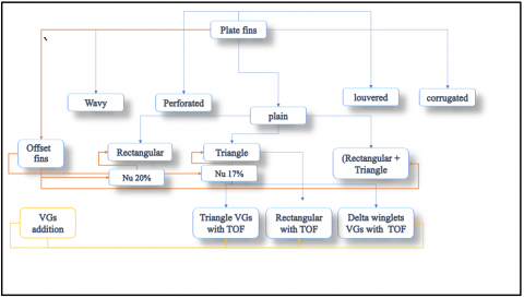
In previous work, a compression has been done for various promising plate fins, including plain fins and offset fins with various shapes (rectangular, triangular, and mixed of both) [10]. To inspect their thermohydraulic features. All offset fin geometries showed an augmentation in thermal properties like Nu compared to the plain ones. A plate-fin heat exchanger (PFHE) equipped with OTF was selected due to its demonstrated 20.32% enhancement in Nusselt number over plain fins (Figure 1) [10]. Three vortex-generator (VG) arrangements, rectangular winglet pair (RWP), delta winglet pair (DWP), and TWP are mounted on the OTF surfaces in a CFU pattern at a 45° attack angle.
Figure 1 illustrates the basic OTF and VG geometry. Key dimensions are:
Figure 1. Classification of plate fins and rationale for selecting OTF based on previous work [10]
2.1 Configurations
Table 1 summarizes the four PFHE cases investigated. All VG cases use an optimum height ($\mathrm{h}_{V G}$) of 1.25 mm and entrance length ($\mathrm{L}_{V G}$) of 0.5 mm at β = 45°.
Table 1. Geometric parameters for proposed PFHE configurations
|
Case |
Fin |
VG Type |
Vh |
VL (mm) |
|
1 |
OTF only |
– |
– |
– |
|
2 |
OTF + RWP (CFU) |
RWP |
1.25 |
0.5 |
|
3 |
OTF + DWP (CFU) |
DWP |
1.25 |
0.5 |
|
4 |
OTF + TWP (CFU) |
TWP |
1.25 |
0.5 |
2.2 Computational domain and boundary conditions
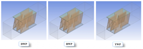
The 3D computational domain for each case is shown in Figure 2. Air enters at $T_{i n}=300 \mathrm{~K}$ with Reynolds number $\operatorname{Re}=600-1400$. Boundary conditions are:
Figure 2. Frontal view of the computational domain for baseline and VG-mounted cases
Note that preliminary conduction analysis indicates that the thermal resistance due to conduction through the fin base is less than 1% of the convective resistance under all tested operating conditions. This was determined by comparing the conduction resistance Rcond = twall/(kwall A) with the convective resistance Rconv = 1/(hA) and finding Rcond/Rconv < 0.01. Therefore, neglecting wall conduction introduces a negligible error in the heat transfer predictions and justifies the thin-wall assumption.
The steady-state, incompressible Navier–Stokes and energy equations are solved using ANSYS Fluent 2021 R1 with:
Finite-volume discretization, second-order upwind for momentum and energy.
SIMPLE algorithm for pressure–velocity coupling.
Mesh independence: residual variation < 1% in friction factor; final cell counts of 186 213 (RWP), 151 214 (DWP), 182 214 (TWP).
Convergence criteria: residuals < 10⁻⁶ for continuity/momentum, < 10⁻⁸ for energy.
2.2.1 Special considerations for vortex and boundary‐layer modeling
No-slip on VG surfaces captures flow separation and longitudinal vortex formation, which intensifies near-wall mixing and disrupts thermal boundary layers [12-14]. This detailed capture of vortical structures is critical to predict the enhanced heat-transfer mechanisms induced by each VG shape.
2.2.2 Numerical implementation
Simulations employed the finite-volume approach with second-order upwind discretization for momentum and energy, and the SIMPLE algorithm for pressure–velocity coupling. Computations ran on a 32-core workstation, averaging 6 h per case to reach converged solutions.
2.3 Governing equations
For fluid motion in the plate fin heat exchanger under laminar conditions, by integrating the average differential equations of continuity, momentum, and energy, the laminar incompressible stable equations can be employed as:
Continuity equation [35]:
$\frac{\delta U}{\delta x}+\frac{\delta V}{\delta y}+\frac{\delta W}{\delta z}=0$ (1)
$\frac{\delta u}{\delta x}+\frac{\delta v}{\delta y}+\frac{\delta w}{\delta z}=0$ (2)
Momentum equations:
The momentum equations were developed using Newton's second rule of motion to address the conservation of fluid momentum over the x, y, and z axes in fluid dynamics [34, 36]. These equations are the Navier-Stokes equations (NSE).
Momentum equation in x-direction:
$\rho\left(u \frac{\delta u}{\delta x}+v \frac{\delta u}{\delta y}+w \frac{\delta u}{\delta z}\right)=-\frac{\delta p}{\delta x}+\left(\frac{\delta^2 u}{\delta x^2}\right)+\left(\frac{\delta^2 u}{\delta y^2}\right)+\left(\frac{\delta^2 u}{\delta z^2}\right)$ (3)
Momentum equation in y-direction:
$\rho\left(u \frac{\delta v}{\delta x}+v \frac{\delta v}{\delta y}+w \frac{\delta v}{\delta z}\right)=-\frac{\delta p}{\delta x}+\left(\frac{\delta^2 v}{\delta x^2}\right)+\left(\frac{\delta^2 v}{\delta y^2}\right)+\left(\frac{\delta^2 v}{\delta z^2}\right)$ (4)
Momentum equation in z-direction:
$u \frac{\delta w}{\delta x}+v \frac{\delta w}{\delta y}+w \frac{\delta w}{\delta z}=-\frac{\delta p}{\delta x}+\left(\frac{\delta^2 w}{\delta x^2}\right)+\left(\frac{\delta^2 w}{\delta y^2}\right)+\left(\frac{\delta^2 w}{\delta z^2}\right)$ (5)
Energy equation:
$\begin{aligned} & u \frac{\delta T}{\delta x}+v \frac{\delta T}{\delta y}+w \frac{\delta T}{\delta z}= -\frac{k}{\rho C_p}+\left(\frac{\delta^2 T}{\delta x^2}\right)+\left(\frac{\delta^2 T}{\delta y^2}\right)+\left(\frac{\delta^2 T}{\delta z^2}\right)\end{aligned}$ (6)
2.4 Computational methods
Numerical simulations are conducted utilizing ANSYS Fluent 2021 R1. The governing equations, comprising continuity, momentum (Navier-Stokes), and energy equations, are resolved via the finite volume approach. A double-precision pressure-based solver is utilized for numerical calculation. The SIMPLE algorithm is employed for pressure-velocity coupling. The spatial discretization of all words is accomplished by a second-order upwind method.
Hydrodynamic parameters:
$P_{\text {in }}-P_{\text {out }}=\Delta P$ (7)
Hydraulic diameter (Dh) [37] as recorded in Eq. (8):
$D_h=\frac{4 A}{P}$ (8)
For Re number [6] as shown in Eq. (9) below:
$R e=\frac{\rho U_{i n} D_h}{\mu}$ (9)
While for Nu number [8] as illustrated in Eq. (10):
$N u=\frac{h D_h}{k}$ (10)
For hydraulic features, including f calculation as in Eq. (11):
$C_f=\tau_w / \frac{1}{2} \rho U^2$ (11)
And for the fanning fraction factor as in Eq. (12):
$C_f=\frac{f}{4}$ (12)
2.5 Grid independence study
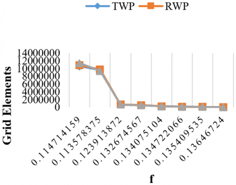
Figure 3 presents the mesh convergence analysis demonstrating how the friction factor (f) and Nusselt number (Nu) stabilize with increasing cell count for each VG configuration at Re = 600. The convergence trends reveal that both parameters show significant variation at lower mesh densities but progressively stabilize as refinement increases. For the RWP configuration, f varies by approximately 8.5% between 50,000 and 100,000 cells, but this variation decreases to less than 0.7% between 150,000 and 186,213 cells. Similarly, Nu changes by 6.3% in the coarser range but by only 0.4% in the finer region. The DWP configuration achieves stability earlier, with variations in f falling below 0.6% and Nu below 0.5% beyond 151,214 cells. The TWP configuration required 182,214 cells to reach similar stability thresholds. These convergence patterns reflect the different geometric complexities of each VG shape, with the more complex RWP geometry requiring higher cell counts to accurately capture the flow physics and heat transfer characteristics, particularly in the wake regions where longitudinal vortices form. The final mesh densities used in this study (186,213 for RWP, 151,214 for DWP, and 182,214 for TWP) ensure that numerical uncertainty related to spatial discretization is minimal.
Figure 3. Mesh independence
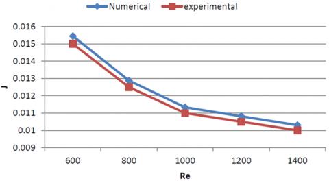
2.6 Validation
The numerical model was confirmed by comparing Colburn j-factor results to Yang et al. [38] experimental data on offset strip fins in PFHEs. Averaging 3% variation between numerical and experimental data spanning the Re 600–1400 showed remarkable agreement. This validation shows that the numerical technique accurately predicts PFHE heat transfer across fin and vortex generator configurations, as illustrated in Figure 4.
Figure 4. Validation for numerical work compared to experimental work
3.1 Heat transfer performance
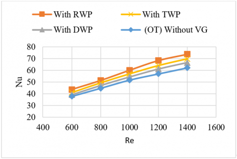
Figure 5 illustrates the impact that the Reynolds number and the geometry of the VGX have on the average Nusselt number. The mean Nusselt number increases in every scenario when compared to the baseline configuration, which consists of only OT fins and no VGX attachment. This is the case regardless of whether the Reynolds number is increased or different VGX forms are introduced. The incorporation of VGX elements results in the generation of secondary flows and the division of the mainstream at the OSF section, which ultimately leads to enhanced mixing between the core and near-wall areas. This enhancement is one of the reasons why this enhancement happens. As a consequence of this, the thermal barrier layer becomes thinner, which in turn makes the process of heat transfer faster and more efficient.
Figure 5. Effect of Reynold number with various types of vortex generator of (β = 45°, Vh = 1.25 mm, VL = 0.5 mm) on the Nu
The RWP form produces the biggest improvement in average Nusselt number, which is approximately 23.6% higher than the OT fin configuration. This is due to the fact that it causes a larger swirl intensity with a well-defined vortex core that is capable of sustaining coherence over longer downstream distances. The rectangular geometry, with its sharp cutting edges, causes greater boundary-layer disruption and enhanced turbulence near the heated surface, which further improves heat transfer. Further improvement is achieved by the rectangular geometry. In comparison, the triangular VGX, which has edges that are more streamlined, generates weaker vortices and, as a result, demonstrates a smaller Nu boost of 19.4%. The delta VGX design, which has the cleanest edges of all the configurations, has the least severe swirl motion. As a result, it has the lowest mean Nu increase of 14.2% when compared to the baseline situation. In line with the patterns that were documented in earlier studies [29, 39, 40], our findings are consistent.
3.2 Pressure drop analysis
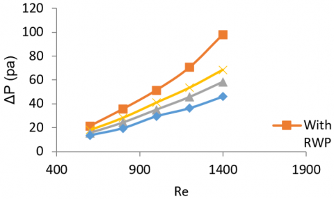
As depicted in Figure 6, the inclusion of VGX attachments leads to a greater pressure drop (ΔP) as compared to the setup that does not contain VGX. This occurs as a result of the installed VGX elements introducing additional flow resistance and obstruction, which impedes the fluid's ability to move in a smooth manner and increases the amount of frictional losses along the flow route. Due to the fact that the rectangular VGX shape has sharp edges and a bigger frontal area, it results in a more robust separation of the flow and the production of larger wake zones behind the element. As a consequence of this, even more noticeable longitudinal vortices and turbulence are produced, which further contribute to an increase in the pressure drop. On the other hand, the triangle and delta VGX shapes, which are distinguished by their edges that are less pointed and more smooth, provide less resistance to the flow and result in the production of a weaker wake. As a result, these topologies are able to record a lower ΔP in comparison to the rectangular VGX, while yet preserving moderate degrees of flow mixing.
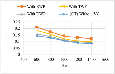
Figure 7 demonstrates that the rectangular VGX configuration has the highest friction factor (f) of all the layouts taken into consideration. A sharper boundary-layer disruption and a bigger turbulence intensity along the channel walls are the results of this phenomenon, which is caused by the sharp-edged geometry and larger flow-facing surface area of the conduit. Shear stress on the walls increases as a consequence of this, which results in an increase in the friction factor. Additionally, the rectangular shape encourages the formation of high-intensity longitudinal vortices, which in turn improve the flow of momentum between the core areas and the wall ones. As a consequence of this, the increased momentum transfer results in more friction losses on the wall, as well as an overall increase in the friction factor when compared to other VGX surfaces.
Figure 6. Effect of Reynold number with various types of vortex generator of (β = 45°, Vh = 1.25 mm, VL = 0.5 mm) on the pressure drop
Figure 7. Effect of Reynold number with various types of vortex generator of (β = 45°, Vh = 1.25 mm, VL = 0.5 mm) on the friction factor
3.3 Performance evaluation factor
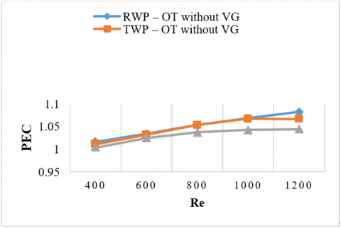
The Performance Evaluation Criterion (PEC) was utilized [41] as a dimensionless metric for the purpose of performance evaluation. This criterion includes the impacts of heat transfer enhancement and pressure drop increase. The utilization of this measure is widespread in the field of heat exchanger optimization studies. This is due to the fact that it guarantees that any enhancement in thermal performance does not result in an excessive increase in the pumping power that is necessary for fluid flow [42, 43]. If the PEC value is more than one, it shows that the enhancement approach is thermally efficient, which means that it produces significantly higher gains in heat transfer than the pressure losses that are associated with it.
As can be seen in Figure 8, the RWP arrangement exhibited the highest PEC in the Reynolds number range of 400–800. This was due to the fact that it produced vortices that successfully boosted heat transfer while retaining a reasonable pressure drop. It was confirmed that there was a favorable thermal–hydraulic balance when the PEC reached 1.18. Re = 800 showed that both RWP and TWP had PEC values that were equivalent to one another, which was roughly 1.12, indicating that they were both efficient. It was noted that a similar pattern emerged as Re grew from 800 to 1600. The delta VGX, on the other hand, results in negligible enhancing effects and produces the lowest PEC value (1.04) among all configurations. This is because the delta VGX has a smoother shape and generates swirls with less force.
Figure 8. Effect of Re with various types of VGX on PEC
4.1 Temperature
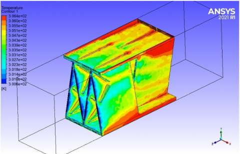
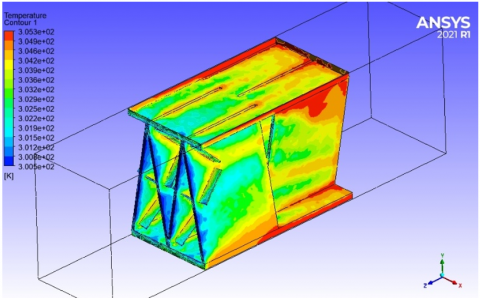
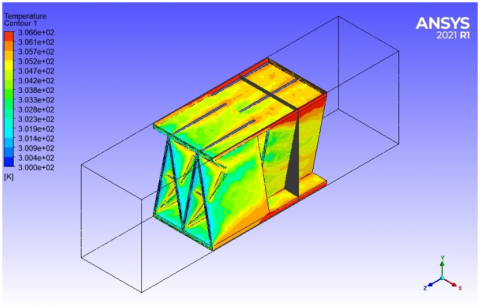
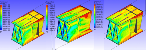
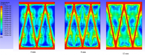
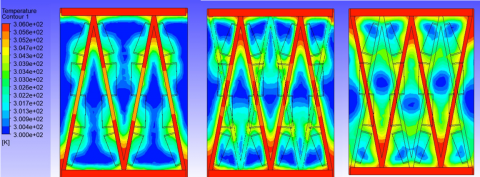
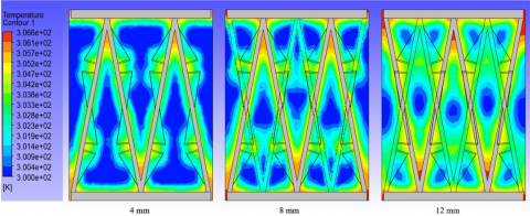
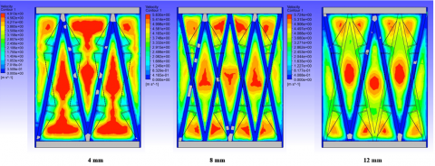
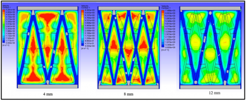
The temperature contours along the tested domain are depicted in Figures 9-15. These figures also include cross-sectional slices that were obtained at 4, 8, and 12 millimeters to demonstrate the differences in temperature that occur for various VGX shapes. Because of the heat absorption from the heated fin surfaces (3,000 W/m2), the outlet air temperature rises gradually as one moves downstream. This is consistent with what was anticipated. In order to visualize this trend, the color transition from dark blue at the entrance to lighter hues (light blue, yellow, and green) toward the outlet indicates a continual rise in air temperature. This transition is depicted by the color transition.
Because of the interaction between the entering cold air and the heated fins, the boundary layer that is close to the walls gets thinner, which results in an increase in the amount of energy that is transmitted to the airflow. As a consequence of this, the outlet temperature at the 12 mm segment is the greatest, which is evidence of the cumulative heat gain that occurs while the channel is being extended. This is because there is less direct contact with hot surfaces in the center region, which results in moderate temperature levels. The highest temperatures are found along the interface between the fin and the wall, which is where convection is at its fiercest.
Quantitatively analyzed, the fins that have rectangular VGX cause the greatest temperature increase in the core region, which is an indication of improved heat transfer ability. The sharp-edged geometry of these structures causes stronger longitudinal vortices to be generated, which in turn intensifies mixing between the core and wall areas. This, in turn, causes the thermal boundary layer to be disrupted, which in turn increases the amount of heat that is transferred through convection. The T-shaped VGX is responsible for a modest boost, but the delta VGX is responsible for the least temperature rise. This is because the delta VGX has a smoother shape and a reduced vortex intensity.
The cut design of OSF fins and the addition of VGX elements generate recurrent boundary-layer disruptions and enhanced flow penetration into the fin base, which ultimately results in greater local heat transfer coefficients. This finding is in line with the findings of prior studies [10, 38, 44]. When taken as a whole, the cause–effect relationship between VGX shape, flow behavior, and temperature distribution makes it abundantly evident that stronger vortex generation results in more thermal enhancement. The rectangular VGX displays the most effective performance in this regard.
Figure 9. 3D view of triangle VGX mounted on OT fins
Figure 10. 3D view of rectangular VGX mounted on OT fins
Figure 11. 3D view of delta VGX mounted on OT fins
Figure 12. 3D view for temperature contours OTF with various VGX geos
Figure 13. 2D front view temp of rectangular VGX mounted on OT fins through various locations (4, 8, and 12) mm
Figure 14. 2D front view temp of triangular VGS mounted on OT fins through various locations (4, 8, and 12) mm
Figure 15. 2D front view temp of Delta VGS mounted on OT fins through various locations (4, 8, and 12) mm
4.2 Velocity
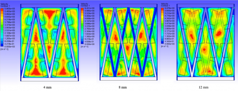
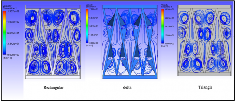
As shown in Figures 16-19, the velocity vectors and temperature fields that highlight the air-side heat transfer and pressure drop characteristics of the fin-tube heat exchanger (FTHEX) are presented. All of the VGX geometries have their contours displayed for three different places along the domain: four, eight, and twelve millimeters. It has been found that the incorporation of VGX elements results in the generation of longitudinal vortices that interact with the main flow. This interaction ultimately results in the formation of swirl zones and a temporary slowdown of the flow in the vicinity of the VGX surfaces. When compared to the darker zones, which correlate to higher flow speeds away from the VGX, these regions appear as lighter colors, which indicates a decrease in velocity.
Figure 16. 2D Velocity front view of rectangular VGS mounted on OT fins through various locations (4, 8, and 12) mm
Figure 17. 2D Velocity front view of delta VGS mounted on OT fins through various locations (4, 8, and 12) mm
Figure 18. 2D Velocity front view of triangle VGS mounted on OT fins through various locations (4, 8, and 12) mm
Figure 19. streamlines for the three proposed VGX (rectangular, delta, and triangle)
Due to the fact that the flow slows down near the VGX as a result of the produced vortices, it stays in touch with the heated surfaces for a longer period of time, which ultimately results in increased local heat transfer rates. In contrast, sections of accelerated flow that are further away from the VGX have a lower level of heat exchange. This is because the reduced residence time restricts the influence of thermal contact. In comparison to other geometries, the rectangular VGX exhibits the fewest areas of low velocity, often known as light zones. This indicates that there is less flow separation and more stable vortex formations overall. On account of this, it displays the most efficient enhancement of heat transport when compared to the delta and triangular VGX designs.
Furthermore, the rectangular VGX demonstrates a 10–15% higher average outlet temperature and a commensurate rise in local Nusselt number in comparison to the delta VGX when the Reynolds number is the same. This substantiates the fact that the rectangular VGX has superior thermal performance. Due to the fact that the delta VGX has a profile that is smoother and narrower, it results in the development of weaker vortices and bigger wake zones, which ultimately makes the heat transfer efficiency less effective.
When compared to the 4 mm segment, the velocity contours at 12 mm indicate higher flow resistance along the flow direction. This is due to the fact that the cumulative pressure losses and the interaction between many vortices worsen downstream. This tendency is further confirmed by the streamline plots that are shown in Figure 19. As shown by the red zones in the temperature field, flow recirculation in the vicinity of the VGX corners, particularly in the triangular arrangement, results in the formation of localized regions of slower heat transport. However, matching and aligning VGX near these corner regions improves mixing and increases the local temperature gradient through amplified vortex motion. This is accomplished by increasing the amount of vortex motion.
As a whole, the investigation reveals that the shape of the VGX is directly responsible for determining the intensity of the vortex, the disruption of the boundary layer, and the rates of local heat transfer. The best balance between strong swirl formation and little flow separation is provided by rectangular VGX. This allows for the maximum amount of convective heat transfer while simultaneously minimizing the amount of pressure loss that occurs.
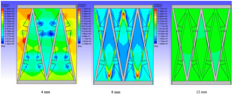
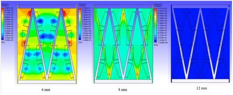
4.3 Pressure
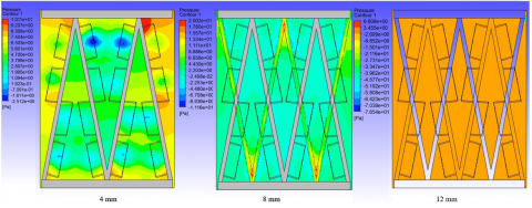
Pressure drop characteristics for proposed VGX configurations are shown in Figures 20-22. The results show that pressure loss is directly related to VGX shape, which controls flow blockage, vortices, and wakes downstream of each element.
When referring to the RWP, the abrupt and perpendicular shape results in a significant flow impingement on the leading face, which in turn results in the formation of a prominent high-pressure area upstream. The winglet experiences a significant pressure drop. This happens when the fluid abruptly breaks from the surface, creating a wide wake region with low pressure. This structure creates massive downstream recirculation zones with high-intensity longitudinal vortices. Figure 20's elongated high–low pressure bands show this. Due to this, the RWP design has the highest pressure drop, 18–22% higher than the triangle and delta designs. RWP design creates a powerful vortex and increases drag.
Flow separation is less abrupt with the TWP due to its streamlined leading edge. Due to the lower pressure differential between the front and rear surfaces, the wake region is smaller, and pressure recovers faster downstream. This causes a 10–12% pressure drop below RWP. However, the effective creation of vortices that promote high thermal mixing is still maintained, as demonstrated in Figure 21. The design of the TWP provides a good balance between increased heat transfer and reduced pressure loss, which is a significant advantage.
To achieve the highest level of aerodynamic efficiency, the DWP is the optimal configuration. The gradual flow dissociation that occurs as a result of its smooth and tapered edges also results in the generation of only minor low-pressure zones that quickly dissipate into the main stream. As a consequence of this, DWP displays the lowest overall pressure difference, typically between 25 and 30 percent lower than RWP. On the other hand, in comparison to the other VGX geometries, this design has a decreased heat transfer enhancement because the vortex intensity associated with it is lower.
In general, the comparison findings indicate that there is a direct cause-and-effect relationship: as the shape of the VGX becomes more streamlined (from rectangular to delta), the produced vortex strength and flow disturbance decrease. This leads to smaller pressure drops, but it also results in a reduction in the performance of heat transfer. As a result, the RWP arrangement gives the greatest improvement in heat transfer, but at the expense of a greater loss of pressure. On the other hand, the DWP configuration delivers the least amount of drag, but only a modest improvement in thermal efficiency.
Figure 20. 2D pressure front view of rectangular VGS mounted on OT fins through various locations (4, 8, and 12) mm
Figure 21. 2D pressure front view of delta VGS mounted on OT fins through various locations (4, 8, and 12) mm
Figure 22. 2D pressure front view of triangular VGX mounted on OT fins through various locations (4, 8, and 12) mm
OTF improved heat transfer in PFHEs in this study. We tested RWP, TWP, and DWP VGX. Each design's thermal and hydraulic performance was evaluated using ANSYS 2021 R1 CFD simulations from 600 to 1400 Reynolds numbers.
Further examination revealed that the RWP design had the greatest thermal increase, with a mean Nusselt number (Nu) of 75. This was much better than the TWP and DWP arrangements, which averaged 70 and 65 Nu values. It's possible that RWP's superior performance is due to the fact that it has the ability to generate powerful and coherent vortices that have a persistent swirl core that extends downstream. It is because of this core that greater mixing and heat transfer are promoted, which ultimately results in improved performance.
Increased heat transfer increases hydraulic disadvantages. RWP had the highest pressure drop (ΔP) at 100 Pa, compared to TWP and DWP at 65 Pa and 60 Pa, respectively. The friction factor (f) for RWP peaked at 0.21 at Re = 600 and then dropped to 0.12 at Re = 1400. Sharp corners and larger flow-facing surfaces increase boundary layer turbulence. The lowest friction factor was 0.16 at low Re and below 0.09 at high Re for DWP. This was possible because its smoother, tapered shape reduced flow separation and turbulence-induced drag. The baseline case without VGX had the lowest friction factors, 0.14-0.085, across all Re. It means flow disruptions were rare.
RWP again led in performance efficiency, as measured by the PEC, with a maximum PEC of 1.08, indicating a good heat transmission-pressure drop balance. The DWP had the lowest PEC, 1.04, reflecting its low thermal benefit over hydraulic cost.
While all VGX designs improve heat transmission, RWP has the best thermal-hydraulic balance. Thus, it is ideal for industrial applications that require compact, efficient PFHE units. Knowing this can improve heat exchanger designs and thermal performance without wasting pumping power. This research benefits HVAC, car cooling, power generation, and chemical processing. Engineers choose VGX shapes based on operational priorities using quantitative data. Energy efficiency, system durability, and cost will be considered.
Future research can improve vortex generator PFHE performance in several ways. First, examine how VGX materials and surface treatments affect heat transmission, friction, and durability. They impact thermal and hydraulic performance. Real-world experiments are needed to validate numerical results and ensure practical implementation. Third, try curved, wavy, helical, or hybrid VGX shapes for thermal enhancement and vortex production. Multi-objective optimization can find the best VGX shape, size, orientation, and position across Reynolds numbers to maximize heat transfer and reduce pressure loss. Study compact or micro-scale PFHE designs with flow limits, transient or high Reynolds flows, and multi-fluid systems using nanofluids or phase-change materials. These studies will improve industrial heat exchanger VGX and personalize them.
|
DWP |
delta winglet pairs |
|
TWP |
triangular winglet pairs |
|
RWP |
rectangular winglet pair |
|
PEC |
performance evaluation criterion |
|
L |
entrance length |
|
β |
angle of attack |
|
Dh |
hydraulic diameter |
|
HE |
heat exchanger |
|
PFHE |
plate-fin heat exchanger |
|
OSF |
offset strip fins |
|
CFU |
common flow up |
|
h |
height |
|
f |
fanning friction-factor |
|
h |
heat transfer coefficient |
|
l |
fin length |
|
P |
perimeter |
|
Q |
heat transfer rate |
|
Re |
Reynolds number |
|
S |
fin spacing |
|
t |
fin thickness |
|
Nu |
Nusselt number |
|
v |
flow velocity |
|
VGX |
vortex generators |
|
Fh |
fin height |
|
fs |
fin spacing |
|
ft |
fin thickness |
|
Vh |
vortex generation height |
|
VL |
vortex generation entrance length |
[1] Thulukkanam, K. (2000). Heat Exchanger Design Handbook. CRC Press.
[2] Marzouk, S.A., Abou Al-Sood, M.M., El-Said, E.M., Younes, M.M., El-Fakharany, M.K. (2023). A comprehensive review of methods of heat transfer enhancement in shell and tube heat exchangers. Journal of Thermal Analysis and Calorimetry, 148(15): 7539-7578. https://doi.org/10.1007/s10973-023-12265-3
[3] Webb, R.L. (1987). Enhancement of single-phase heat transfer. Handbook of Single-Phase Convective Heat Transfer.
[4] Sabri, A., Nabil, R., Yehia, N., Santos, T. (2024). Heat transfer and weight enhancements for traditional finned tube heat exchangers using various needle fin shapes. Journal of Advanced Research in Fluid Mechanics and Thermal Sciences, 127(1): 161-174. https://doi.org/10.37934/arfmts.127.1.161174
[5] Abbas, N.Y., Sabri, A., Nabil, R. (2025). Investigation of improving heat transfer efficiency using perforated fins: A review. Journal of Advanced Research in Fluid Mechanics and Thermal Sciences, 132(1): 22-46.
[6] Nabil, R., Sabri, A. (2022). A review on the modification of circular fin and tube heat exchangers through new innovative fin shapes. International Journal of Advanced Technology and Engineering Exploration, 9(93): 1222. http://dx.doi.org/10.19101/IJATEE.2021.875888
[7] Shah, R.K., Sekulic, D.P. (2003). Fundamentals of Heat Exchanger Design. John Wiley & Sons.
[8] Abbas, A.S., Mohammed, A.A. (2022). Enhancement of plate-fin heat exchanger performance with aid of various types of fin configurations: A review. Journal of Advanced Research in Fluid Mechanics and Thermal Sciences, 99(2): 48-66. https://doi.org/10.37934/arfmts.99.2.4866
[9] Zheng, X., Qi, Z. (2018). A comprehensive review of offset strip fin and its applications. Applied Thermal Engineering, 139: 61-75. https://doi.org/10.1016/j.applthermaleng.2018.04.101
[10] Abbas, A.S., Mohammed, A.A. (2022). Augmentation of Plate-fin heat exchanger performance with support of various types of fin configurations. Mathematical Modelling of Engineering Problems, 9(5): 1406-1414. https://doi.org/10.18280/mmep.090532
[11] Dewatwal, J. (2009). Design of compact plate fine heat exchanger. Doctoral Dissertation, National Institute of Technology Rourkela.
[12] Awais, M., Bhuiyan, A.A. (2018). Heat transfer enhancement using different types of vortex generators (VGs): A review on experimental and numerical activities. Thermal Science and Engineering Progress, 5: 524-545. https://doi.org/10.1016/j.tsep.2018.02.007
[13] Henze, M., Von Wolfersdorf, J., Weigand, B., Dietz, C.F., Neumann, S.O. (2011). Flow and heat transfer characteristics behind vortex generators–A benchmark dataset. International Journal of Heat and Fluid Flow, 32(1): 318-328. https://doi.org/10.1016/j.ijheatfluidflow.2010.07.005
[14] Eiamsa-Ard, S., Promvonge, P. (2011). Influence of double-sided delta-wing tape insert with alternate-axes on flow and heat transfer characteristics in a heat exchanger tube. Chinese Journal of Chemical Engineering, 19(3): 410-423. https://doi.org/10.1016/S1004-9541(11)60001-3
[15] Abbas, A.S., Mohammed, A.A. (2023). Enhancement of plate-fin heat exchanger performance with aid of (RWP) vortex generator. International Journal of Heat and Technology, 41(3): 780-788. https://doi.org/10.18280/ijht.410336
[16] Wang, Y., Oon, C.S., Foo, J.J., Tran, M.V., Nair, S.R., Low, F.W. (2023). Numerical investigation of thermo-hydraulic performance in an annular heat exchanger with sinusoidal vortex generators. Journal of Thermal Analysis and Calorimetry, 148(20): 10973-10990. https://doi.org/10.1007/s10973-023-12375-y
[17] Priyadi, M.U.Z. (2022). Heat transfer enhancement in heat exchanger using convex delta winglet vortex generators. European Journal of Engineering and Technology Research, 7(6): 96-100. https://doi.org/10.24018/ejeng.2022.7.6.2920
[18] Hukire, P.R., Sawant, S.M., Warade, M.V.P. (2018). Numerical analysis of application of vortex generator in perforated plate-fin heat sink. JournalNX, 290-293.
[19] Batista, J., Trp, A., Lenic, K. (2022). Heat transfer enhancement of crossflow air-to-water fin-and-tube heat exchanger by using delta-winglet type vortex generators. Energies, 15(6): 2070. https://doi.org/10.3390/en15062070
[20] Saini, P., Dhar, A., Powar, S. (2023). Performance enhancement of fin and tube heat exchanger employing curved trapezoidal winglet vortex generator with circular punched holes. International Journal of Heat and Mass Transfer, 209: 124142. https://doi.org/10.1016/j.ijheatmasstransfer.2023.124142
[21] Sinha, A., Raman, K.A., Chattopadhyay, H., Biswas, G. (2013). Effects of different orientations of winglet arrays on the performance of plate-fin heat exchangers. International Journal of Heat and Mass Transfer, 57(1): 202-214. https://doi.org/10.1016/j.ijheatmasstransfer.2012.10.034
[22] Zhou, G., Feng, Z. (2014). Experimental investigations of heat transfer enhancement by plane and curved winglet type vortex generators with punched holes. International Journal of Thermal Sciences, 78: 26-35. https://doi.org/10.1016/j.ijthermalsci.2013.11.010
[23] Du, X., Feng, L., Yang, Y., Yang, L. (2013). Experimental study on heat transfer enhancement of wavy finned flat tube with longitudinal vortex generators. Applied Thermal Engineering, 50(1): 55-62. https://doi.org/10.1016/j.applthermaleng.2012.05.024
[24] Samadifar, M., Toghraie, D. (2018). Numerical simulation of heat transfer enhancement in a plate-fin heat exchanger using a new type of vortex generators. Applied Thermal Engineering, 133: 671-681. https://doi.org/10.1016/j.applthermaleng.2018.01.062
[25] He, Y., Han, H., Tao, W., Zhang, Y. (2012). Numerical study of heat-transfer enhancement by punched winglet-type vortex generator arrays in fin-and-tube heat exchangers. International Journal of Heat and Mass Transfer, 55(21-22): 5449-5458. https://doi.org/10.1016/j.ijheatmasstransfer.2012.04.059
[26] Sarangi, S.K., Mishra, D.P. (2024). A comprehensive review on vortex generator supported heat transfer augmentation techniques in heat exchangers. Journal of Thermal Analysis and Calorimetry, 149(15): 7839-7867. https://doi.org/10.1007/s10973-024-13369-0
[27] Chai, L., Tassou, S.A. (2018). A review of airside heat transfer augmentation with vortex generators on heat transfer surface. Energies, 11(10): 2737. https://doi.org/10.3390/en11102737
[28] Fiebig, M. (1995). Embedded vortices in internal flow: Heat transfer and pressure loss enhancement. International Journal of Heat and Fluid Flow, 16(5): 376-388. https://doi.org/10.1016/0142-727X(95)00043-P
[29] Tavakoli, M.R., Akbari, O.A., Mohammadian, A., Pourfattah, F. (2024). Investigation of the effect of rectangular winglet angles on turbulent flow and heat transfer of water/Cu nanofluid in a three-dimensional channel. Heliyon, 10(16): e36482. https://doi.org/10.1016/j.heliyon.2024.e36482
[30] Song, K., Tagawa, T. (2018). The optimal arrangement of vortex generators for best heat transfer enhancement in flat-tube-fin heat exchanger. International Journal of Thermal Sciences, 132: 355-367. https://doi.org/10.1016/j.ijthermalsci.2018.06.011
[31] Carpio, J., Valencia, A. (2021). Heat transfer enhancement through longitudinal vortex generators in compact heat exchangers with flat tubes. International Communications in Heat and Mass Transfer, 120: 105035. https://doi.org/10.1016/j.icheatmasstransfer.2020.105035
[32] Hu, D., Zhang, Q., Song, K., Gao, C., Zhang, K., Su, M., Wang, L. (2023). Performance optimization of a wavy finned-tube heat exchanger with staggered curved vortex generators. International Journal of Thermal Sciences, 183: 107830. https://doi.org/10.1016/j.ijthermalsci.2022.107830
[33] Lemouedda, A., Breuer, M., Franz, E., Botsch, T., Delgado, A. (2010). Optimization of the angle of attack of delta-winglet vortex generators in a plate-fin-and-tube heat exchanger. International Journal of Heat and Mass Transfer, 53(23-24): 5386-5399. https://doi.org/10.1016/j.ijheatmasstransfer.2010.07.017
[34] Joardar, A., Jacobi, A.M. (2008). Heat transfer enhancement by winglet-type vortex generator arrays in compact plain-fin-and-tube heat exchangers. International Journal of Refrigeration, 31(1): 87-97. https://doi.org/10.1016/j.ijrefrig.2007.04.011
[35] Mahdi, H. (2004). Numerical and experimental study of enhancement of heat transfer in roughened ribbed duct. Doctoral Dissertation, Department of technical Eduction, University of technology, Iraq.
[36] Saysroy, A., Eiamsa-Ard, S. (2017). Enhancing convective heat transfer in laminar and turbulent flow regions using multi-channel twisted tape inserts. International Journal of Thermal Sciences, 121: 55-74. https://doi.org/10.1016/j.ijthermalsci.2017.07.002
[37] Abbas, N.Y., Mustafa, A.W., Askera, M.K.A.A. (2021). Constructal design of heat exchangers: A review. International Journal of Advances in Engineering and Management, 3(12): 27-40.
[38] Yang, H., Wen, J., Wang, S., Li, Y. (2018). Effect of fin types and Prandtl number on performance of plate-fin heat exchanger: Experimental and numerical assessment. Applied Thermal Engineering, 144: 726-735. https://doi.org/10.1016/j.applthermaleng.2018.08.063
[39] Wu, J.M., Tao, W.Q. (2008). Numerical study on laminar convection heat transfer in a rectangular channel with longitudinal vortex generator. Part A: Verification of field synergy principle. International Journal of Heat and Mass Transfer, 51(5-6): 1179-1191. https://doi.org/10.1016/j.ijheatmasstransfer.2007.03.032
[40] Lin, Z.M., Wang, L.B., Lin, M., Dang, W., Zhang, Y.H. (2017). Numerical study of the laminar flow and heat transfer characteristics in a tube inserting a twisted tape having parallelogram winglet vortex generators. Applied Thermal Engineering, 115: 644-658. https://doi.org/10.1016/j.applthermaleng.2016.12.142
[41] Maradiya, C., Vadher, J., Agarwal, R. (2018). The heat transfer enhancement techniques and their thermal performance factor. Beni-Suef University Journal of Basic and Applied Sciences, 7(1): 1-21. https://doi.org/10.1016/j.bjbas.2017.10.001
[42] Xue, Y., Ge, Z., Du, X., Yang, L. (2018). On the heat transfer enhancement of plate fin heat exchanger. Energies, 11(6): 1398. https://doi.org/10.3390/en11061398
[43] Tu, W., Tang, Y., Zhou, B., Lu, L. (2014). Experimental studies on heat transfer and friction factor characteristics of turbulent flow through a circular tube with small pipe inserts. International Communications in Heat and Mass Transfer, 56: 1-7. https://doi.org/10.1016/j.icheatmasstransfer.2014.04.020
[44] Yang, Y., Li, Y., Si, B., Zheng, J. (2015). Performance evaluation of heat transfer enhancement for offset strip fins used in plate-fin heat exchangers. Journal of Heat Transfer, 137(10): 101901. https://doi.org/10.1115/1.4030247