Jesús Palacios Muñoz![]() | David Tumbillo Quispe
| David Tumbillo Quispe![]() | Juan Valdez Loaiza
| Juan Valdez Loaiza![]() | Yuri Silva Vidal
| Yuri Silva Vidal![]() | José Canazas*
| José Canazas*![]() | Christofer Diaz
| Christofer Diaz![]()
© 2025 The authors. This article is published by IIETA and is licensed under the CC BY 4.0 license (http://creativecommons.org/licenses/by/4.0/).
OPEN ACCESS
Coolants are a fundamental component in the performance of heat exchange systems. Specifically, in a gas turbine power plant intercooler, coolants are used to cool the hot air prior to the second compression stage. Advanced coolants such as nanofluids can improve heat transfer performance in these systems. This study investigates the thermal performance and pressure drop of an intercooler in a gas turbine power plant using graphene oxide-based nanofluids as the working medium. This intercooler was proposed based on two existing commercial technologies. Three cases were evaluated with different compression ratios in each compression stage. The results, initially evaluating the base fluid, showed that design parameters such as flow and temperature influence the heat transfer performance and pressure drop of the system. The intercooler's thermal efficiency is higher for cases with a higher compression ratio in the first stage of compression. Furthermore, the temperature delta influences system sizing. Finally, the addition of nanofluids showed an increase in the overall heat transfer coefficient and a reduction in the total intercooler volume. This study demonstrates the potential for implementing new commercial intercooler technologies in gas turbine plants.
nanofluids, heat transfer, graphene oxide, gas turbine, intercooler
Gas turbine power plants are essential to modern energy infrastructure, offering rapid start-up capabilities, high power density, and fuel flexibility [1, 2]. Improving their thermodynamic performance remains a priority in both stationary applications, such as those mentioned above, as well as mobile applications in the aeronautical and marine industries [3]. A well-established strategy to improve thermal efficiency is the incorporation of intercoolers between the compression stages. Intercoolers reduce the temperature of the compressed air before it enters the high-pressure compressor, thus decreasing the compression work and increasing the net production of the cycle [4-6]. Currently, there are commercial solutions for gas turbine systems that have been fitted with an intercooler, such as the LMS100 aeroderivative engine manufactured by General Electric, and the WR-21 marine engine manufactured by Westinghouse and Rolls-Royce [3]. However, the thermal performance of these systems is inherently limited by the heat transfer properties of conventional coolants, such as water or ethylene glycol, which restricts the compactness and overall efficiency of the heat exchanger [7].
Nanofluids, nanoscale colloidal solutions consisting of nanoparticles (ranging in size from 1 to 100 nm) dispersed in a base fluid, have attracted the interest of researchers in recent decades [8]. When nanoparticles are uniformly dispersed in base fluids, the resulting suspension shows remarkable improvement in thermal properties [9]. Several works in the literature have applied nanofluids in thermosyphons, electronic cooling modules, heat pipes, microchannel heat sinks, heat exchangers, refrigeration systems, among others [10]. For example, Panday and Singh [11] evaluated the performance of a plate heat exchanger using CuO–water nanofluids at various concentrations and flow conditions through experiments and simulations. It identifies 3% nanoparticle concentration as optimal and provides correlations for key thermal and flow properties. Also, Roshani et al. [12] studied the thermal and hydrodynamic performance of a plate pin-finned heat sink using alumina–water and titanium dioxide–water nanofluids at various concentrations. While both nanofluids improve heat transfer and reduce thermal resistance, they also increase pumping power, with alumina–water showing slightly better overall performance. Among nanofluids, those based on graphene oxide (GO) offer distinctive advantages such as high thermal conductivity, excellent dispersion stability, and favorable rheological properties. The unique two-dimensional structure and functionalized surfaces of graphene oxide nanoparticles facilitate efficient thermal transport, making them especially suitable for high-performance cooling applications [13]. For example, Singh et al. [14] presented an experimental and computational analysis of the performance of compact plate heat exchangers (PHEs) using graphene oxide nanofluids at different concentrations and flow rates. The results indicated that the use of nanofluids increased the thermal conductivity by 13%, heat transfer rate by 14%, efficiency by 9%, and overall heat transfer coefficient by 10% at the expense of pressure drop and pumping power. On the other hand, Ranjbarzadeh et al. [15] experimentally studied the effect of using water/graphene oxide nanofluid as the working fluid on heat transfer and pressure drop in a copper tube under air crossflow. The results showed that by using nanofluid, the Nusselt number was improved by up to 51.4% compared to pure water. The friction factor increased by 21% compared to pure water. The heat transfer coefficient of performance increased to 42.2%, indicating improved heat transfer compared to the undesirable pressure drop in the test.
In addition to the application of nanofluids in gas turbine systems working with an intercooler, other innovative ideas have been proposed in the literature such as the implementation of a reheating stage before entering the combustion chamber [16, 17], the coupling of a Rankine cycle to the system [18, 19], or the use of hydrogen in gas turbines [20, 21]. However, despite the growing interest in nanofluids for heat exchanger applications, little attention has been paid to their implementation in gas turbine intercooler systems [22]. Among the few studies that addressed the topic, Zhao et al. [23] conducted a theoretical study on the use of Al2O3–water and Cu–water nanofluids as alternatives to conventional coolants in a marine gas turbine intercooler system. Using the NTU-effectiveness method, heat transfer and flow performance were evaluated, considering nanofluid concentrations between 1 and 5 vol.% and applying known correlations for thermophysical properties. The effects of nanoparticle concentration, inlet temperature, Reynolds number, and gas-side parameters were examined. The findings showed that nanofluids improved heat transfer and reduced pumping power requirements compared to water under all turbine operating conditions. Similarly, Almurtaji et al. [24] examined the performance of a marine gas turbine intercooler using MWCNT-water nanofluids, prepared by a two-step method at 10-50℃ with concentrations of 0.01-0.10 vol.% and stabilized by SDS (1:1 weight ratio with MWCNTs). The results showed that the nanofluids were more effective the longer their residence time in the intercooler, highlighting the importance of heat exchanger design and working fluid selection. Furthermore, higher gas inlet temperatures improved the nanofluid’s effectiveness.
In the study of gas turbine power plants using intercoolers, it is important to highlight that there is no ideal heat exchanger solution. Commercial solutions, such as the LMS100, implement shell-and-tube heat exchangers cooled by a cooling tower, or alternatively, a compact heat exchanger cooled by forced ventilation [25]. Other studies propose the use of a condenser [6]. It is also important to mention that in recent years, compact water-cooled heat exchangers have gained significant interest in industry. This is because compactness is important in this type of gas turbine heat exchangers, and significant optimization can be achieved through a detailed analysis of exchanger performance [26].
Graphene oxide nanofluids frequently perform better than conventional coolants and many other nanofluids because the oxygen-containing functional groups enhance wetting and dispersion (so the particles stay suspended and transfer heat more uniformly) and the 2-D GO sheets provide a very high specific surface area and strong phonon/electron pathways that increase effective thermal conductivity at very low loadings [13]. In many trials, this combination produces significant heat transfer enhancement with a smaller volumetric viscosity penalty than for high-loading spherical particles. It tends to increase convective heat transfer (higher Nusselt numbers) without requiring huge particle concentrations. In contrast to aggressive loadings of other nanoparticles, the practical advantage lies in the ability to achieve useful conductivity/heat transfer gains at very low concentrations and with good long-term stability, which minimizes the pumping penalty. The trade-off is that GO (and especially reduced GO) can increase viscosity, and thus pressure drop at higher concentrations [27, 28].
Despite these developments, the majority of research on nanofluids for heat exchangers has focused on carbon nanotube-based fluids or metal oxide nanoparticles like CuO, Al2O3, and TiO2, mostly on laboratory-scale exchangers and electrical or refrigeration systems. These fluids showed significant gains in thermal performance, but they also had problems with dispersion stability and increased viscosity, which might penalize pumping power and pressure drop, especially in gas turbine intercoolers that have high temperatures and large flows. Therefore, there is still a need to find nanofluid formulations that are appropriate for these demanding conditions by combining low viscosity, good thermal conductivity, and long-term suspension stability [13, 29].
While nanofluids have been extensively studied in heat exchangers, their use in gas turbine intercoolers has not been thoroughly explored. To the best of our knowledge, few studies have been published on gas turbine intercoolers using nanofluids as coolant. Therefore, this study seeks to address heat transfer and pressure drop analysis of a gas turbine intercooler using graphene oxide nanofluids. This intercooler is a compact air-to-coolant heat exchanger that combines two existing commercial technologies for these systems. Through a parametric investigation, the effect of the compression ratio at each stage of the system, the coolant-side temperature delta, and the nanoparticle concentration on system performance are evaluated. These results contribute to the broader goal of improving gas turbine performance through advanced thermal management, supporting cleaner and more efficient power generation.
2.1 System layout
In this study, a simple gas turbine cycle is considered, consisting of two axial compressors (one low-pressure and one high-pressure) with an air-cooler intercooler between them, a combustion chamber, and an expansion turbine, as shown in Figure 1. The performance of each component and, consequently, the overall performance of the gas turbine cycle will not be studied in this work [30]. However, some operational parameters of the system are considered variables for the intercooler analysis. After compression in the first compressor, the compressed air enters the intermediate intercooler, and after reducing the temperature of the compressed air, it enters the second compressor.

Figure 1. Layout of the proposed gas turbine system with intercooler [30]
This system will be used in a power generation plant. Since there is currently only one commercial model, the General Electric LMS100, operational parameters for this turbine will be considered based on previous studies and other studies considering the efficient operation of a gas turbine. Table 1 shows these parameters for three proposed cases with different compression ratio configurations in the two compression stages. The first case has compression ratios of 3.2 and 12.5, the second 4 and 10, and the third 5 and 8, all for the first and second compression stages, respectively. In all three cases, a total compression ratio of 40 is obtained.
Table 1. Operating conditions at the gas turbine power generation plant
|
Parameter |
Case 1 |
Case 2 |
Case 3 |
Source |
|
Intercooler air inlet temperature (K) |
421.3 |
451.2 |
483.1 |
Eq. (1) |
|
Intercooler air outlet temperature (K) |
311.9 |
334.1 |
358.1 |
Eq. (2) |
|
Air mass flow rate (kg/s) |
50 |
50 |
50 |
[24, 31] |
|
Intercooler coolant inlet temperature (K) |
293 |
293 |
293 |
Initial Condition |
|
Intercooler coolant outlet temperature (K) |
298-302 |
298-302 |
298-302 |
[23, 25] |
Considering an ambient temperature of 293 K (inlet temperature to the low-pressure compressor) for all cases, the air inlet temperature to the intercooler can be determined, as shown in Eq. (1), considering the compression ratio and an isentropic compressor efficiency of 90%, and the specific heat ratio of the air. Therefore, while the high-pressure compressor inlet temperature is theoretically expected to be equivalent to the low-pressure compressor inlet temperature, this is not guaranteed in real-life environments. Furthermore, for the purpose of properly comparing the three proposed cases, we will assume that the combustion inlet air temperature is 700 K. From this, we obtain the intercooler air outlet temperature presented in Eq. (2).
$T_2=T_1+\frac{T_1}{\eta_{c_1}}\left[r_{c_1}^{\frac{\gamma_a-1}{\gamma a}}-1\right]$ (1)
$T_3=\frac{T_4}{1+\frac{r_{c_2}^{\frac{r_a-1}{\gamma_a}}-1}{\eta_{c_2}}}$ (2)
where, the compression ratios are:
$r_{c_1}=\frac{P_2}{P_1}$ (3)
$r_{c_2}=\frac{P_4}{P_3}$ (4)
2.2 Intercooler description and mathematical model
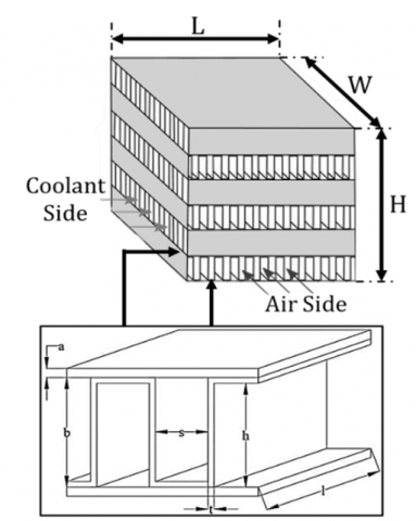
As previously mentioned, the intercooler to be studied and sized will be a compact heat exchanger. Nowadays, there are many alternatives and configurations for this type of heat exchanger, generally modifying geometric details is the most important [32]. The configuration to be used will be a plate-fin for the air side and the coolant side, with the same structural dimensions on both sides. This intercooler configuration is widely used in the mobile heavy machinery industry, power generation plants, chemical processing, automotive, and oil and gas industries [33-35], and is similar to the one proposed for the WR-21 marine engine [36]. A schematic of this proposed configuration is shown in Figure 2, and its dimensions are summarized in Table 2. The dimensions of this configuration were used based on experimental data obtained working with air-air and air-liquid systems [26].
Figure 2. Schematic geometries of the configuration (Reproduced from the studies [7, 37])
Table 2. Structural design configuration
|
Parameter |
Symbol |
Both Sides |
|
Fin configuration |
- |
Plain |
|
Fin thickness (mm) |
t |
0.25 |
|
Fin height (mm) |
h |
10.05 |
|
Plate spacing (mm) |
b |
10.3 |
|
Fin spacing (mm) |
s |
3.8 |
|
Plate thickness (mm) |
a |
0.8 |
The LMS100 gas turbine uses an external intercooler located between its low- and high-pressure compressors—typically a large tubular heat exchanger that cools the compressed air with water or glycol before re-entering the core—which improves efficiency but takes up considerable space. In contrast, the WR-21 turbine integrates a highly compact plate-and-fin intercooler and recuperator into its core to achieve high thermal efficiency and reduced fuel consumption in confined marine environments. A hybrid design combining the LMS100's external location with the WR-21's compact, finned geometry could outperform both by providing higher heat transfer rates per volume, lower airside temperatures at similar pressure drops, and lower duct losses, achieving higher cycle efficiency and faster thermal response, while maintaining accessibility and modularity for maintenance.
Table 3. Equations of the geometric parameters
|
Parameter |
Formula |
Equation |
|
Hydraulic radius (m2) |
$r_h=\frac{D_h}{4}=\frac{2 s h}{s+h}$ |
(5) |
|
Total transfer area/volume between plates (m2/m3) |
$\beta=\frac{2(h+s)}{b(s+t)}$ |
(6) |
|
Total transfer area/ total exchanger volume (m2/m3) |
$\alpha=\frac{\beta b}{b(s+t)}$ |
(7) |
|
Free flow area/frontal area |
$\sigma=r_h \alpha$ |
(8) |
The following assumptions will be used for the analysis: (1) The intercooler operates in a steady state. (2) The thickness of all fins is assumed to be uniform and their thermal resistance is negligible. (3) All parts are made of the same material, aluminum. (4) The influences of dirt and corrosion are ignored.
Steady-state analysis was considered because the turbine under evaluation is considered for a power generation plant. Then the plant operates most of the time at constant load, with infrequent start-up and shutdown regime changes. The effects of fouling and corrosion can be ignored in the intercooler analysis, since the compressed air and coolant operate in clean, controlled circuits with adequate filtration and treatment. Furthermore, the intercooler is manufactured with corrosion-resistant materials, and fouling or degradation processes occur on much longer timescales than those in the operational analysis, so their influence on thermal performance is minimal. However, these assumptions may overestimate thermal performance, since in practice transient variations and deposits reduce the heat transfer coefficient and the effectiveness of the intercooler.
For the analysis, some parameters of the geometries for the air and coolant sides are required to analyze the radiator performance. The equations for obtaining these parameters are shown in Table 3 [26].
For the present heat transfer study, it is worth highlighting again that we have defined the inlet parameters of temperature, pressure, and mass flow of air to the intercooler. For the coolant, we also consider a fixed ambient inlet temperature, a pumping pressure sufficient to pass through the intercooler, and a fixed coolant mass flow rate. Since we do not have the dimensions, the intercooler is a compact heat exchanger, and we can use Eq. (9) to examine the thermal equilibrium on both the coolant and air sides [7]. With this, we can determine the coolant mass flow rate required in the system.
$Q=\dot{m}_c c_c\left(T_{c, o}-T_{c, i}\right)=\dot{m}_a c_a\left(T_{a, i}-T_{a, o}\right)$ (9)
Eqs. (10) and (11) evaluate the mass velocity and Reynolds number on both sides. On both sides, the mass velocity is considered by fin spacing. It is important to highlight that to obtain the mass velocity, the frontal area on both sides of the flow is required. This data is not known in principle, since we are interested in determining the size of the heat exchanger. Therefore, this analysis results in an iterative process with more than one solution, for which we will determine and evaluate several dimensions to understand the heat transfer and pressure drop behavior in these cases. This process is described after obtaining the overall heat transfer coefficient.
$G=\frac{\dot{m}}{\sigma A_{f r}}$ (10)
$R e=\frac{D_h G}{\mu}$ (11)
where,
$A_{f r, a}=L H$ (12)
$A_{f r, c}=W H$ (13)
To obtain the intercooler dimension, the overall airside heat transfer coefficient is required, which requires the convection heat transfer coefficients and the surface efficiencies of the coolant-side and air-side fins. The procedure for obtaining these parameters is described below. First, taking into account the friction factor for turbulent flow, which was defined by Vajjha et al. [38] in Eq. (14), Gnielinski [39] developed an equation for turbulent flow shown in Eq. (15).
$f_c=0.3164 R e_c^{-0.25}\left(\frac{\rho_{n f}}{\rho_{b f}}\right)^{0.797}\left(\frac{\mu_{n f}}{\mu_{b f}}\right)^{0.108}$ (14)
$N u_c=\frac{\left(\frac{f_c}{8}\right)\left(R e_c-1000\right) P r_c}{1+12.7 \sqrt{\frac{f_c}{8}}\left(P r_c^{\frac{2}{3}}-1\right)}$ (15)
Then, the heat transfer coefficient of the coolant side is shown in Eq. (16).
$h_c=\frac{N u_c k_c}{D_{h, c}}$ (16)
Data from Kays and London [26] on a single plate fin surface were curve fitted to create a correlation for the Colburn factor, which is in good agreement with the structural parameters listed in Table 3. Shown in Eqs. (17) and (18) are the Colburn factor and friction factor respectively for turbulent air flow up to a Reynolds number of 12000 [7].
$j_a=-3.8 * 10^{-8} R e_a+0.00348$ (17)
$f_a=-2.4 * 10^{-11} R e_a^2-5.9 * 10^{-7} R e_a+0.0108$ (18)
Then, the convective heat transfer coefficient of the air side is shown in Eq. (19).
$h_a=\frac{j_a G_a c_a}{P r_a^{2 / 3}}$ (19)
Thus, to obtain the overall heat transfer coefficient, shown in Eq. (23), the surface effectiveness of the fins is part of the balance of the heat transfer coefficient; it is calculated using the fin efficiency (Eq. (21)) and the fin area divided by the total area. In obtaining the overall heat transfer coefficient, the very small wall resistance is neglected, and is considered, in this case, equivalent since we use the same structural parameters on both sides.
$m_f=\sqrt{\frac{2 h_{\text {fluid }}}{k_{\text {Al }} t}}$ (20)
$\eta_f=\frac{\tanh \left(m_f(h+t)\right)}{m_f(h+t)}$ (21)
$\eta_o=1-\frac{A_f}{A_t}\left(1-\eta_f\right)$ (22)
$\frac{1}{U}=\frac{1}{\eta_{o, a} h_a}+\frac{1}{\eta_{o, c} h_c}$ (23)
Then, using the ϵ-NTU method, we will determine the heat transfer area of the heat exchanger. Eq. (24) shows the calculation of the effectiveness, and using Eq. (25), which is for cross-flow heat exchangers with both fluids unmixed, we obtain the NTU.
$\begin{aligned} \epsilon=\frac{q}{q_{\max }}=\frac{C_a\left(T_{a, \text { in }}-T_{a, \text { out }}\right)}{C_{\min }\left(T_{a, \text { in }}-T_{c, \text { in }}\right)} = \frac{C_c\left(T_{c, \text { in }}-T_{c, \text { out }}\right)}{C_{\min }\left(T_{a, \text { in }}-T_{c, \text { in }}\right)}\end{aligned}$ (24)
$\epsilon=1-\exp \left[\frac{\exp \left(-N T U^{0.78} C\right)-1}{N T U^{-0.22} C}\right]$ (25)
where,
$C_a=\dot{m}_a c_a$ (26)
$C_c=\dot{m}_c c_c$ (27)
$C=\frac{C_{\min }}{C_{\max }}$ (28)
Next, we evaluate the area using the relationship in Eq. (29). As mentioned above, this result is compared to the proposed initial heat transfer area shown in Eq. (30), resulting in a process with more than one solution depending on the proposed heat exchanger dimensions.
$A=\frac{C_{\min } N T U}{U}$ (29)
$A=\alpha V$ (30)
where,
$V=W L H$ (31)
Finally, Eq. (32) provides the following expression for a relationship for the pressure drop of single-phase fluid. Then, with the heat exchanger dimensions already known, we can obtain the pressure drop on each side.
$\Delta P=\frac{f L G^2}{2 D_h \rho}$ (32)
2.3 Thermophysical properties of fluids
The analysis requires correlations for the density, specific heat, dynamic viscosity, and thermal conductivity of the base fluid, air, and nanofluids. By curve fitting within a suitable temperature range, correlations were created from these data. Table 4 shows the correlations for the thermodynamic and transport properties of air with a coefficient of determination very close to 1. The data were obtained from previous studies considered as databases for air [40-42]. It can be observed in this case that only the density depends on the static pressure; that is, the specific volume of air changes with this parameter. In the case of the other properties, although they also depend on the change in static pressure, these are much less influenced.
Table 4. Correlations of the thermophysical properties of air for 300 K ≤ T ≤ 500 K (And for density: 100 kPa ≤ P ≤ 600 kPa)
|
Property |
Correlation |
Equation |
|
Density (kg/m3) |
$\rho=\frac{P}{286.9 T}$ |
(33) |
|
Specific Heat (J/kg‧K) |
$c=3.85 * 10^{-4} T^2-0.18 T+1025.73$ |
(34) |
|
Thermal conductivity (W/m‧K) |
$k=6.95 * 10^{-5} T+4.94 * 10^{-3}$ |
(35) |
|
Viscosity (Pa‧s) |
$\mu=2.54 * 10^{-11} T^2-6.12 * 10^{-8} T+2.49 * 10^{-6}$ |
(36) |
Table 5. Correlations of the thermophysical properties of water for 290 K ≤ T ≤ 310 K
|
Property |
Correlation |
Equation |
|
Density (kg/m3) |
$\rho=-4.78 * 10^{-3} T^2+2.56 T+653.58$ |
(37) |
|
Specific Heat (J/kg‧K) |
$c=-2.19 * 10^{-2} T+4189.6$ |
(38) |
|
Thermal conductivity (W/m‧K) |
$k=-9.73 * 10^{-6} T^2+7.49 * 10^{-3} T-0.77$ |
(39) |
|
Viscosity (Pa‧s) |
$\mu=3.48 * 10^{-7} T^2-2.28 * 10^{-4} T+3.79 * 10^{-2}$ |
(40) |
According to the literature on the working fluid in intercoolers, there is no consensus on the most appropriate fluid; however, some details are considered depending on the application. For example, in several applications, a combination of water and ethylene glycol is used due to the environmental conditions, since the fluid’s boiling point is higher and its freezing point is lower. Similarly, in the WR21 marine engine, seawater is used for intercooling. Therefore, water will be used as the base fluid in this study, due to its abundance and favorable thermophysical properties over ethylene glycol and its combinations, in addition to the greater number of studies on suspended nanoparticles in this fluid. These properties are shown in Table 5 with a coefficient of determination close to 1. The property data were obtained from several sources considered as a database for water [43-45] and a curve was fitted as a function of temperature, in a range of 290 K to 310 K that the system will encounter.
Although nanofluids have been the subject of testing and research, there is a lack of a comprehensive analysis of their properties from some aspects, due for example to the different syntheses of nanomaterials, as well as other physical-chemical parameters [46, 47]. However, we can refer to some research carried out to obtain these characteristics. The density and specific heat of nanofluids at various temperatures and concentrations have been predicted using the correlations shown in Eqs. (41) and (42), respectively [48, 49]. In the case of graphene oxide nanosheets, their density has an estimated value of 1000 kg/m3 [50], while their specific heat of 700 J/kg‧K [51, 52].
$\rho_{n f}=\phi \rho_{n p}+(1-\phi) \rho_{b f}$ (41)
$(\rho c)_{n f}=\phi(\rho c)_{n p}+(1-\phi)(\rho c)_{b f}$ (42)
According to the study conducted by Ranjbarzadeh et al. [53], correlations were developed for the thermal conductivity and viscosity of graphene oxide dispersed in water for a range of temperatures (293 K ≤ T ≤ 353 K) and concentrations (0.04% ≤ $\phi$ ≤ 0.16%) shown in Eqs. (43) and (44) respectively. The correlation of thermal conductivity followed a model proposed by previous research with graphene oxide [54, 55]. While the correlation of viscosity was evaluated with models analogous to nanofluids [56].
$\frac{k_{n f}}{k_{b f}}=0.998+0.022(T-273)^{0.81} \phi^{1.01}$ (43)
$\frac{\mu_{n f}}{\mu_{b f}}=1.89 e^{\frac{-9.41}{T-273}+3.71 \phi}$ (44)
It is important to mention that in the specific case of graphene oxide, some physical and chemical parameters are slightly more influential compared to conventional metallic nanomaterials. For example, the level of oxidation, the average number of layers after exfoliation, the surface area size, and even defects within the nanosheet itself influence the thermophysical properties and, consequently, its performance as a working fluid.
In this section, we will discuss the influence of three relevant conditions on the design of these systems. First, we will evaluate the three proposed cases, i.e., different compression ratios in each stage, and how this influences the intercooler’s thermohydraulic performance. Another important factor to consider is the cooling system that can be proposed to cool the water passing through the intercooler. This is related to the temperature delta or the water mass flow rate; in this case, we will evaluate the former. Finally, we will analyze the implementation of nanofluids in the system to evaluate the intercooler’s heat transfer performance and pressure drop.
3.1 Influence of the compression ratio
Key intercooler design parameters will be examined, such as the overall heat transfer coefficient, the heat exchanger volume, and the pressure drops on the coolant and air sides. Figure 3 shows the effect of each proposed case on the overall heat transfer coefficient for different air Reynolds numbers. This analysis was performed for the same coolant temperature delta of 7 K at the intercooler. The airside temperature deltas were 109.4 K, 117.1 K, and 125.0 K for each case, respectively. Thus, the lower the compression ratio in the first compressor, the lower the water mass flow rate required in the intercooler, and consequently, the lower the coolant Reynolds number. The different data were obtained for intercooler widths ranging from 0.4 m to 0.9 m. It is possible to identify that the trend for each case is the same: for the lowest air Reynolds number evaluated, 4000, the overall heat transfer coefficient is almost constant. While the air Reynolds number increases, the overall heat transfer coefficient tends to increase slightly as the coolant Reynolds number increases. On the one hand, this behavior can be explained by the fact that turbulent flows involve greater heat transfer on both sides of the intercooler. On the other hand, these results, with an air Reynolds number of 12,000, also show that as the coolant Reynolds number increases, a nearly constant value of the overall heat transfer coefficient is reached. Quantitatively, there was an increase in the overall heat transfer coefficient comparing the lowest and highest air Reynolds numbers evaluated: 232.6%, 237.8%, and 239.5% for each case, respectively.

Figure 3. Effect of the compression ratio in each stage on the overall heat transfer coefficient for different air Reynolds numbers
As support for the results obtained previously, Figure 4 shows the effect of the compression ratio in each stage on the overall heat exchanger volume for different air Reynolds numbers. It can be seen that as the coolant Reynolds number increases, the heat exchanger volume remains almost constant for all cases and different air Reynolds numbers. It can be observed that as the compression ratio in the first compressor increases, a smaller heat exchanger volume is required for the regimes studied. The need for a larger volume is a consequence of requiring a larger heat transfer surface area. These values do not have an inverse trend similar to that of the overall heat transfer coefficient because for each defined air Reynolds number, the coolant mass flows are consequently different, ultimately influencing the NTU value and the intercooler effectiveness. Additionally, it’s understandable that higher Reynolds numbers on both sides result in an intercooler with a significantly reduced volume. For example, for the airside Reynolds number of 12,000, there was a 212% reduction in volume between Case 1 and Case 3, while for the airside Reynolds number of 4,000, there was a 206% reduction between the two cases.

Figure 4. Effect of the compression ratio in each stage on the heat exchanger volume for different air Reynolds numbers
Then, analyzing the hydraulic performance of the intercooler with both fluids, Figures 5 and 6 show the effect of the compression ratio in each stage on the pressure drop on the coolant and air sides, respectively, for different air Reynolds numbers. The pressure drop results on the coolant side in Figure 5 are shown on a logarithmic scale. It is possible to see that, on the one hand, increasing the air Reynolds number implies a drop in coolant pressure. This is because, as seen in the previous figure, larger heat exchangers imply longer coolant flow distances. On the other hand, increasing the coolant Reynolds number also tends to increase, because although the friction factor may be slightly lower, the increase in coolant mass flow overcomes it. Additionally, with the increase in the compression ratio in the first compressor in the system, the pressure drop value is lower, requiring less pumping power.

Figure 5. Effect of the compression ratio in each stage on the coolant-side pressure drop for different air Reynolds numbers

Figure 6. Effect of the compression ratio in each stage on the airside pressure drop for different air Reynolds numbers
Figure 6 shows the opposite behavior of the air-side pressure drop to that shown in Figure 5. For low air-side Reynolds numbers, a practically constant pressure drop behavior can be observed, while at high Reynolds numbers and for the low compression ratio in the first compressor, there is a slight decline with increasing coolant Reynolds number. On the other hand, an increasing decline in the pressure drop is also evident as the compression ratio in the first compressor increases. This can be explained by the fact that the air temperature is higher in the third case, and consequently, its viscosity decreases much more. In general, for an air Reynolds number of 12,000, the pressure drop represents only 0.13%, 0.06%, and 0.04% of the intercooler inlet pressure for each case, respectively.
The combined effect of enhanced coolant-side convective performance and increased heat duty is the main reason why cases with a higher first-stage compression ratio need a smaller intercooler volume. Higher temperatures cause more heat to be extracted from the hot air entering the intercooler, increasing the necessary coolant mass flow and, in turn, the coolant Reynolds number for a fixed air mass flow. A greater air-coolant temperature differential raises the driving LMTD, while a higher coolant Reynolds number results in a bigger coolant-side convective coefficient (via Nusselt number dependence on Reynolds number). As a result, a smaller heat transfer area is needed for the same heat duty, and the overall heat transfer coefficient U rises. We see that the coolant mass-flow strategy determines this outcome; if the coolant mass flow were maintained constant, the area would have to expand to fulfill the higher duty.
From the results presented above, it is evident that two-stage gas turbine systems with different compression ratios influence intercooler performance. Increasing the compression ratio in the first compressor results in a higher overall heat transfer coefficient and lower heat exchanger volume and coolant-side pressure drop. However, increasing the compression ratio too much in this compressor could raise the temperature too much, requiring much more energy in the second compression stage and affecting the overall cycle efficiency.
3.2 Influence of the temperature delta on the intercooler
This section presents the evaluated parameters influenced by the temperature delta in the intercooler. In the previous section, they were evaluated with a delta of 7 K. In this section, the parameters with deltas of 5 K and 9 K will be analyzed. Figure 7 shows the overall heat transfer coefficient evaluated over a range of coolant Reynolds numbers for the three proposed temperature deltas. It can be noted that the change in this temperature delta does not significantly change the heat transfer coefficient. Although the change in the delta implies a variation in the coolant mass flow rate, for the temperature delta values studied, it represents a progressive and inversely proportional increase in the heat transfer area (to achieve the same or very close values). Additionally, it is possible to identify the growth of the overall heat transfer coefficient as the coolant Reynolds number increases, since this increased mass flow rate also encourages greater heat transfer. In addition to the above discussion, Figure 8 shows the influence of the three proposed temperature deltas on the heat exchanger volume for a range of coolant Reynolds numbers. All three curves show a decrease in heat exchanger volume as the coolant Reynolds number increases. This is due to the justification explained in the previous paragraph: a smaller heat transfer area is required with a higher overall heat transfer coefficient. Furthermore, it can be observed that as the temperature delta increases, the volume decreases. This is likely related to the increase in the coolant Reynolds number and, consequently, to the heat transfer on this side, which leads to a reduction in the heat transfer area.

Figure 7. Overall heat transfer coefficient evaluated at different coolant-side temperature deltas for Rea = 10000

Figure 8. Heat exchanger volume evaluated at different coolant side temperature deltas for Rea = 10000
Now, regarding the influence of the coolant-side temperature delta on the pressure drop, in Figures 9 and 10, we visualize this parameter for the coolant and air sides, respectively. Initially, in Figure 9, we can observe, in relation to the results from the previous section, that the trend for this parameter will be similar, although with different values. We can identify that the coolant pressure drop is greater as the temperature delta increases. On the one hand, although the coolant viscosity decreases slightly with a larger delta, the coolant mass flow rate becomes more relevant in this analysis. On the other hand, having a larger heat exchanger volume means that the pressure drop is understandably greater. Figure 10 shows a similar trend to the previous one on the air side. As the temperature increases, there is also a greater pressure drop on the air side. In this case, having a constant temperature, this parameter was influenced by the length of the air side of the heat exchanger.

Figure 9. Coolant-side pressure drop evaluated at different coolant-side temperature deltas for Rea = 10000

Figure 10. Air-side pressure drop evaluated at different temperature deltas on the coolant side for Rea = 10000
From the results obtained in this section, we can identify that while the overall heat transfer coefficient is practically unchanged depending on the temperature delta on the coolant side, other design parameters become relevant. Therefore, by reducing the temperature delta, we can reduce the design and hydraulic parameters without affecting heat transfer. However, even though the pressure drop is reduced with this value, the mass flow rate of the coolant increases, and consequently, greater pumping power is required, not because of the pressure drop, but because of the coolant flow rate.
3.3 Influence of nanofluid concentration
In this third section of results, the previously analyzed thermohydraulic parameters will be evaluated with the addition of graphene oxide nanofluids. These results were evaluated with a coolant temperature delta of 7 K. Figure 11 shows the influence of nanofluid concentration on the overall heat transfer coefficient across a range of coolant Reynolds numbers. The increase in this parameter is clear as the concentration of the nanosheets increases. A noticeable increase can be observed even at the lowest concentration, but this increase is slightly reduced at higher concentrations.
Figure 12 shows the influence of nanofluids on the heat exchanger volume. As discussed above, while this parameter is influenced by the temperature delta and the overall heat transfer coefficient, in this case, the thermophysical properties of the fluid may also be more important. For example, the thermal conductivity of the base fluid increases with increasing temperature, and the increase in this property with increasing temperature is greater in nanofluids. Even the specific heat is slightly reduced in the case of nanofluids; however, it is not as influential as thermal conductivity. Therefore, the application of nanofluids makes it possible to design smaller heat transfer equipment.

Figure 11. Overall heat transfer coefficient evaluated at different nanofluid concentrations for Rea = 10000
Now, regarding the pressure drop on both sides, Figures 13 and 14 show the influence of nanofluid concentration on the coolant and air sides, respectively. First, Figure 13 clearly shows the increase in pressure drop with increasing concentration. The addition of nanosheets greatly increases viscosity and, consequently, greater pumping resistance, requiring greater power. Second, Figure 14 shows the decrease in pressure drop on the air side due to the decrease in heat exchanger volume. From these results, it is possible to identify the potential of adding nanoparticles to base fluids for use in heat transfer systems. Although greater pumping power is required in the systems for proper operation, it is possible to identify that even at small concentrations there is a notable improvement in the total heat transfer coefficient, which is reflected in the substantial reduction in the heat exchanger volume.
By improving the coolant-side heat transfer coefficient and coolant thermal conductivity at low concentrations, graphene oxide nanofluids can allow for quantifiable intercooler volume reductions or increased intercooler effectiveness for a fixed package. Therefore, in practice a compact GO-cooled plate-fin core can replace a larger shell-and-tube core for retrofits, increasing power output or lowering inlet temperatures for the HP compressor; designers should aim for low to moderate GO concentrations and use pump-power minimization as the optimization goal; and a smaller compact plate-fin core can achieve the same intercooling duty, improving packaging and reducing duct lengths and associated losses.

Figure 12. Heat exchanger volume evaluated at different nanofluid concentrations for Rea = 10000

Figure 13. Coolant-side pressure drop evaluated at different nanofluid concentrations for Rea = 10000

Figure 14. Air-side pressure drop evaluated at different nanofluid concentrations for Rea = 10000
Finally, the reasons why compression ratio, cooling temperature difference, and nanofluid concentration affect intercooler performance: First, increasing the first compressor's compression ratio raises the intercooler's air inlet temperature, which enhances heat duty. This, in turn, tends to raise the overall convective heat transfer coefficient and lower the exchanger volume needed for the same duty through greater coolant flow and Reynolds number. Then higher coolant delta temperature usually requires higher coolant mass flow (therefore higher pump power), but it also reduces the required exchanger area since fewer coolant passes or less area are needed to remove the same heat. Lastly, higher GO concentrations allow for smaller cores by improving heat conductivity and the overall convective heat transfer coefficient, but they also increase viscosity and coolant-side pressure drop. Consequently, there is an ideal concentration that strikes a compromise between pumping penalties and heat-transfer gains.
In this study, the heat transfer performance and pressure drop of an intercooler in a gas turbine power plant were analyzed using graphene oxide nanofluids. Initially, the influence of different compression ratio pairs in both compression stages was evaluated, working with the base fluid. Next, the influence of the temperature delta on the coolant side of the intercooler was analyzed, also with the base fluid. Finally, the influence of the graphene oxide nanofluid concentration on intercooler performance was evaluated. Initially, the impact of the compression ratio on intercooler sizing is evident. While the temperature increase due to increased pressure at the air-side intercooler inlet increases the heat transfer coefficient, high temperatures can affect the overall efficiency of the cycle. Therefore, the coolant temperature delta in the intercooler is also important in the design of these heat exchangers. Reducing the temperature delta can lead to a reduction in the exchanger volume and pressure drop, but the pump flow rate requirement will be greater, influencing pumping power. Finally, the addition of nanoparticles to the base fluid showed improvements in the intercooler’s thermal performance. An increase in the overall heat transfer coefficient and a reduction in exchanger volume were observed with increasing nanoparticle concentration. However, an increase in the pressure drop on the coolant side is reflected in the increased viscosity of the working fluid.
This study is limited by its one-dimensional and steady-state modeling technique, which ignores transient operation, detailed turbulence, and possible long-term impacts such as fouling or nanoparticle aggregation. Additionally, corrosion and material compatibility were not assessed. Long-term stability testing of graphene oxide nanofluids, experimental validation under realistic flow and temperature conditions, and three-dimensional CFD simulations with turbulence models should all be part of future research. Furthermore, investigating functionalized or hybrid nanofluids may aid in enhancing thermal performance and reducing viscosity-related drawbacks. According to the findings, graphene oxide nanofluids, as opposed to traditional coolants, can improve intercooler efficiency or enable smaller, lighter heat exchangers. Practically speaking, this could allow for smaller plate-fin intercoolers for contemporary maritime or aeroderivative gas turbines, which would save installation volume and ducting losses. Moderate GO concentrations could enhance cooling performance for retrofitting existing systems, like LMS100 or WR-21 designs, without requiring significant design changes. These results give manufacturers recommendations on how to maximize coolant flow rate, exchanger design, and nanofluid concentration in order to increase thermal efficiency while minimizing pumping penalties. This study demonstrates the application of nanofluids in gas turbine plant cooling systems, as well as the possibility of integrating new commercial intercooler technologies into gas turbine plants.
|
t |
fin thickness, mm |
|
h |
fin height, mm |
|
b |
plate spacing, mm |
|
l |
fin length, mm |
|
s |
fin spacing, mm |
|
a |
plate thickness, mm |
|
D |
diameter, mm |
|
r |
radius, mm |
|
L |
length, mm |
|
W |
width, mm |
|
H |
height, mm |
|
A |
area, m2 |
|
V |
volumetric flow, m3/s |
|
m |
mass flow, kg/s |
|
Q |
heat transfer rate, W |
|
c |
specific heat, J/(kg-℃) |
|
k |
thermal conductivity, (W/m-℃) |
|
T |
temperature, ºC |
|
h |
convective coefficient, W/(m2-℃) |
|
G |
mass air flow, kg/s-m2 |
|
Re |
Reynolds number |
|
Pr |
Prandtl number |
|
Nu |
Nusselt number |
|
U |
overall heat transfer coefficient, W/(m2-℃) |
|
f |
Friction factor |
|
j |
Colburn factor |
|
ΔP |
pressure drop, Pa |
|
Greek symbols |
|
|
$\alpha$ |
total transfer area/total exchanger volume, m2/m3 |
|
$\beta$ |
total transfer area/volume between plates, m2/m3 |
|
$\rho$ |
density, m3/kg |
|
$\eta$ |
efficency, % |
|
$\mu$ |
dynamic viscosity, Pa.s |
|
$\sigma$ |
free flow area/frontal area |
|
$\varphi$ |
fin surface area/Total transfer area |
|
$\phi$ |
nanofluid concentration |
|
$\gamma$ |
heat capacity ratio |
|
$\epsilon$ |
effectiveness |
|
Subscripts |
|
|
fr |
frontal |
|
c |
coolant side |
|
a |
air side |
|
h |
hydraulic parameter |
|
nf |
nanofluid |
|
bf |
basefluid |
|
np |
nanoparticle |
[1] Farhat, H., Salvini, C. (2022). Novel gas turbine challenges to support the clean energy transition. Energies, 15(15): 5474. https://doi.org/10.3390/en15155474
[2] Fujita, D., Miyazaki, T. (2024). Investigating the effect of natural gas composition on centrifugal gas compressors used in gas turbine power plants. International Journal of Energy Production and Management, 9(3): 181-186. https://doi.org/10.18280/ijepm.090307
[3] Lebedev, A.S., Kostennikov, S.V. (2008). Trends in increasing gas-turbine units efficiency. Thermal Engineering, 55: 461-468. https://doi.org/10.1134/s0040601508060037
[4] Canière, H., Willockx, A., Dick, E., De Paepe, M. (2006). Raising cycle efficiency by intercooling in air-cooled gas turbines. Applied Thermal Engineering, 26(16): 1780-1787. https://doi.org/10.1016/j.applthermaleng.2006.02.008
[5] Almutairi, A.S., Pilidis, P., Al-Mutawa, N. (2016). Exergetic, exergoeconomic and exergoenvironmental analysis of intercooled gas turbine engine. In 52nd AIAA/SAE/ASEE Joint Propulsion Conference, Salt Lake City, UT. https://doi.org/10.2514/6.2016-5060
[6] Candra, O., Ali, A., Askar, S., Bhat, R.S., et al. (2023). Thermal and environmental optimization of an intercooled gas turbine toward a sustainable environment. Chemosphere, 339: 139624. https://doi.org/10.1016/j.chemosphere.2023.139624
[7] Canazas, J., Kamyshnikov, O. (2022). Heat transfer and pressure drop performance of a hydraulic mining shovel radiator by using ethylene glycol/water-based Al2O3 nanofluids. International Journal of Heat and Technology, 40(1): 273-281. https://doi.org/10.18280/ijht.400132
[8] Taylor, R., Coulombe, S., Otanicar, T., Phelan, P., Gunawan, A., Lv, W., Rosengarten, G., Prasher, R., Tyagi, H. (2013). Small particles, big impacts: A review of the diverse applications of nanofluids. Journal of Applied Physics, 113(1): 011301. https://doi.org/10.1063/1.4754271
[9] Bhatti, M.M. (2021). Recent trends in nanofluids. Inventions, 6(2): 39. https://doi.org/10.3390/inventions6020039
[10] Rashidi, S., Hormozi, F., Karimi, N., Ahmed, W. (2021). Chapter 14 - Applications of nanofluids in thermal energy transport. In Emerging Nanotechnologies for Renewable Energy, pp. 345-368. https://doi.org/10.1016/b978-0-12-821346-9.00018-3
[11] Panday, N.K., Singh, S.N. (2022). Performance evaluation of plate heat exchanger using CuO-DI water nanofluid. Journal of Thermal Science and Engineering Applications, 14(12): 121007. https://doi.org/10.1115/1.4055153
[12] Roshani, M., Ziaeddin Miry, S., Hanafizadeh, P., Ashjaee, M. (2015). Hydrodynamics and heat transfer characteristics of a miniature plate pin-fin heat sink utilizing Al2O3–water and TiO2–water nanofluids. Journal of Thermal Science and Engineering Applications, 7(3): 031007. https://doi.org/10.1115/1.4030103
[13] Rodriguez, J.C.C., Mamani, R.D.V., Vidal, Y.L.S. (2025). A short overview on aqueous graphene oxide suspensions for application in thermal heating systems. Journal of Engineering Science and Technology Review, 18(4): 9-16. https://doi.org/10.25103/jestr.184.03
[14] Singh, S., Verma, P., Ghosh, S.K. (2021). Numerical and experimental analysis of performance in a compact plate heat exchanger using graphene oxide/water nanofluid. International Journal of Numerical Methods for Heat & Fluid Flow, 31(11): 3356-3372. https://doi.org/10.1108/hff-08-2020-0539
[15] Ranjbarzadeh, R., Meghdadi Isfahani, A.H., Afrand, M., Karimipour, A., Hojaji, M. (2017). An experimental study on heat transfer and pressure drop of water/graphene oxide nanofluid in a copper tube under air cross-flow: Applicable as a heat exchanger. Applied Thermal Engineering, 125: 69-79. https://doi.org/10.1016/j.applthermaleng.2017.06.110
[16] Okati, V., Moghadam, A.J., Farzaneh-Gord, M., Moein-Jahromi, M. (2023). 4E and multi-criteria optimization of a new alternative intercooling method for modified Brayton cycle on the operation of a hybrid energy system. Iranian Journal of Science and Technology, Transactions of Mechanical Engineering, 48: 881-906. https://doi.org/10.1007/s40997-023-00708-z
[17] Dabwan, Y.N., Pei, G., Kwan, T.H., Zhao, B. (2021). An innovative hybrid solar preheating intercooled gas turbine using parabolic trough collectors. Renewable Energy, 179: 1009-1026. https://doi.org/10.1016/j.renene.2021.07.057
[18] Han, X.Q., Dai, Y.B., Guo, X.H., Braimakis, K., Karellas, S., Yan, J.J. (2024). A novel dual-stage intercooled and recuperative gas turbine system integrated with transcritical organic Rankine cycle: System modeling, energy and exergy analyses. Energy, 305: 132252. https://doi.org/10.1016/j.energy.2024.132252
[19] Liu, W., Zhang, X.Y., Zhao, N.B., Shu, C.Y., Zhang, S.K., Ma, Z.J., Han, J. (2018). Performance analysis of organic Rankine cycle power generation system for intercooled cycle gas turbine. Advances in Mechanical Engineering, 10(8). https://doi.org/10.1177/1687814018794074
[20] Sodhro, A.A., Lemma, T.A., Gilani, S.I.U.H., Salilew, W.M. (2024). Comparative performance analysis of gas turbine with and without intercooler using natural gas and hydrogen fuels. Engineering, Technology & Applied Science Research, 14(6): 18283-18289. https://doi.org/10.48084/etasr.8825
[21] Ali, A., Houda, M., Waqar, A., Khan, M.B., Deifalla, A., Benjeddou, O. (2024). A review on application of hydrogen in gas turbines with intercooler adjustments. Results in Engineering, 22: 101979. https://doi.org/10.1016/j.rineng.2024.101979
[22] Alsayegh, A., Ali, N. (2020). Gas turbine intercoolers: Introducing nanofluids—A mini-review. Processes, 8(12): 1572. https://doi.org/10.3390/pr8121572
[23] Zhao, N.B., Wen, X.Y., Li, S.Y. (2016). An evaluation of the application of nanofluids in intercooled cycle marine gas turbine intercooler. Journal of Engineering for Gas Turbines and Power, 138(1): 012201. https://doi.org/10.1115/1.4031170
[24] Almurtaji, S., Ali, N., Teixeira, J.A., Addali, A. (2021). Effect of multi-walled carbon nanotubes-based nanofluids on marine gas turbine intercooler performance. Nanomaterials, 11(9): 2300. https://doi.org/10.3390/nano11092300
[25] Ol’khovskii, G.G., Radin, Y.A., Ageev, A.V., Chertkov, A.I. (2016). Thermal tests of LMS100 gas-turbine units at the Dzhubga thermal power plant. Power Technology and Engineering, 50: 294-302. https://doi.org/10.1007/s10749-016-0699-2
[26] Kays, W.M., London, A.L. (1998). Compact Heat Exchangers. 3rd Edition, McGraw-Hill, New York.
[27] Cham sa-ard, W., Fawcett, D., Fung, C.C., Chapman, P., Rattan, S., Poinern, G.E.J. (2021). Synthesis, characterisation and thermo-physical properties of highly stable graphene oxide-based aqueous nanofluids for potential low-temperature direct absorption solar applications. Scientific Reports, 11: 16549. https://doi.org/10.1038/s41598-021-94406-y
[28] Mirzaei, M., Azimi, A. (2015). Heat transfer and pressure drop characteristics of graphene oxide/water nanofluid in a circular tube fitted with wire coil insert. Experimental Heat Transfer, 29(2): 173-187. https://doi.org/10.1080/08916152.2014.973975
[29] Almurtaji, S., Ali, N., Teixeira, J.A., Addali, A. (2020). On the role of nanofluids in thermal-hydraulic performance of heat exchangers—A review. Nanomaterials, 10(4): 734. https://doi.org/10.3390/nano10040734
[30] Ghojel, J. (2020). Fundamentals of Heat Engines: Reciprocating and Gas Turbine Internal Combustion Engines. Wiley.
[31] Ying, Y.L., Cao, Y.P., Li, S.Y., Wang, Z.T. (2013). Study on flow parameters optimisation for marine gas turbine intercooler system based on simulation experiment. International Journal of Computer Applications in Technology, 47(1): 56-67. https://doi.org/10.1504/ijcat.2013.054302
[32] Saha, S.K., Ranjan, H., Emani, M.S., Bharti, A.K. (2019). Internally finned tubes and spirally fluted tubes. In Heat Transfer Enhancement in Externally Finned Tubes and Internally Finned Tubes and Annuli. Springer Briefs in Applied Sciences and Technology, pp. 85-126. https://doi.org/10.1007/978-3-030-20748-9_6
[33] Sanaye, S., Hajabdollahi, H. (2010). Thermal-economic multi-objective optimization of plate fin heat exchanger using genetic algorithm. Applied Energy, 87(6): 1893-1902. https://doi.org/10.1016/j.apenergy.2009.11.016
[34] Canazas, J. (2021). Field study on the air-side heat transfer performance of copper finned-flat tubes for heavy-duty truck radiators. International Journal of Heat and Technology, 39(5): 1451-1459. https://doi.org/10.18280/ijht.390506
[35] Ray, D.R., Das, D.K. (2014). Superior performance of nanofluids in an automotive radiator. Journal of Thermal Science and Engineering Applications, 6(4): 041002. https://doi.org/10.1115/1.4027302
[36] Crisalli, A.J., Parker, M.L. (1993). Overview of the WR-21 intercooled recuperated gas turbine engine system: A modern engine for a modern fleet. In Proceedings of the ASME 1993 International Gas Turbine and Aeroengine Congress and Exposition, Cincinnati, Ohio, USA. https://doi.org/10.1115/93-gt-231
[37] Mehendale, S.S. (2018). Single-phase heat exchangers. In Handbook of Thermal Science and Engineering, pp. 1447-1472. https://doi.org/10.1007/978-3-319-26695-4_21
[38] Vajjha, R.S., Das, D.K., Kulkarni, D.P. (2010). Development of new correlations for convective heat transfer and friction factor in turbulent regime for nanofluids. International Journal of Heat and Mass Transfer, 53(21-22): 4607-4618. https://doi.org/10.1016/j.ijheatmasstransfer.2010.06.032
[39] Gnielinski, V. (2013). On heat transfer in tubes. International Journal of Heat and Mass Transfer, 63: 134-140. https://doi.org/10.1016/j.ijheatmasstransfer.2013.04.015
[40] Lemmon, E.W., Jacobsen, R.T., Penoncello, S.G., Friend, D.G. (2000). Thermodynamic properties of air and mixtures of nitrogen, argon, and oxygen from 60 to 2000 K at pressures to 2000 MPa. Journal of Physical and Chemical Reference Data, 29(3): 331-385. https://doi.org/10.1063/1.1285884
[41] Touloukian, Y.S., Liley, P.E., Saxena, S.C. (1970). Thermophysical Properties of Matter, Volume 3, Thermal Conductivity-Nonmetallic Liquids and Gases. IFI/Plenum.
[42] Touloukian, Y.S., Saxena, S.C., Hestermans, P. (1975). Thermophysical Properties of Matter, Volume 11, Viscosity. IFI/Plenum.
[43] Wagner, W., Pruß, A. (2002). The IAPWS formulation 1995 for the thermodynamic properties of ordinary water substance for general and scientific use. Journal of Physical and Chemical Reference Data, 31(2): 387-535. https://doi.org/10.1063/1.1461829
[44] Huber, M.L., Perkins, R.A., Laesecke, A., Friend, D.G., et al. (2009). New International formulation for the viscosity of H2O. Journal of Physical and Chemical Reference Data, 38(2): 101-125. https://doi.org/10.1063/1.3088050
[45] Huber, M.L., Perkins, R.A., Friend, D.G., Sengers, J.V., Assael, M.J., Metaxa, I.N., Miyagawa, K., Hellmann, R., Vogel, E. (2012). New international formulation for the thermal conductivity of H2O. Journal of Physical and Chemical Reference Data, 41(3): 033102. https://doi.org/10.1063/1.4738955
[46] Li, J.H., Zhang, X.L., Xu, B., Yuan, M.Y. (2021). Nanofluid research and applications: A review. International Communications in Heat and Mass Transfer, 127: 105543. https://doi.org/10.1016/j.icheatmasstransfer.2021.105543
[47] Sheikh, N.A., Chuan Ching, D.L., Khan, I. (2020). A comprehensive review on theoretical aspects of nanofluids: Exact solutions and analysis. Symmetry, 12(5): 725. https://doi.org/10.3390/sym12050725
[48] Pak, B.C., Cho, Y.I. (1998). Hydrodynamic and heat transfer study of dispersed fluids with submicron metallic oxide particles. Experimental Heat Transfer, 11(2): 151-170. https://doi.org/10.1080/08916159808946559
[49] Xuan, Y.M., Roetzel, W. (2000). Conceptions for heat transfer correlation of nanofluids. International Journal of Heat and Mass Transfer, 43(19): 3701-3707. https://doi.org/10.1016/s0017-9310(99)00369-5
[50] Ranjbarzadeh, R., Karimipour, A., Afrand, M., Isfahani, A.H.M., Shirneshan, A. (2017). Empirical analysis of heat transfer and friction factor of water/graphene oxide nanofluid flow in turbulent regime through an isothermal pipe. Applied Thermal Engineering, 126: 538-547. https://doi.org/10.1016/j.applthermaleng.2017.07.189
[51] Naik, G., Krishnaswamy, S. (2017). Photoreduction and thermal properties of graphene-based flexible films. Graphene, 6(2): 27-40. https://doi.org/10.4236/graphene.2017.62003
[52] Gałek, R., Wilk, J. (2024). Investigations of the specific heat capacity of selected heterogeneous materials. Archives of Thermodynamics, 45(2): 91-98. https://doi.org/10.24425/ather.2024.150855
[53] Ranjbarzadeh, R., Akhgar, A., Taherialekouhi, R., D’Orazio, A., Mohammad Sajadi, S., Ghaemi, F., Baleanu, D. (2022). Improve the heat exchanger efficiency via examine the Graphene Oxide nanoparticles: A comprehensive study of the preparation and stability, predict the thermal conductivity and rheological properties, convection heat transfer and pressure drop. Journal of Thermal Analysis and Calorimetry, 147: 7509-7521. https://doi.org/10.1007/s10973-021-11002-y
[54] Mei, X.Y., Sha, X., Jing, D.W., Ma, L.J. (2022). Thermal conductivity and rheology of graphene oxide nanofluids and a modified predication model. Applied Sciences, 12(7): 3567. https://doi.org/10.3390/app12073567
[55] Taherialekouhi, R., Rasouli, S., Khosravi, A. (2019). An experimental study on stability and thermal conductivity of water-graphene oxide/aluminum oxide nanoparticles as a cooling hybrid nanofluid. International Journal of Heat and Mass Transfer, 145: 118751. https://doi.org/10.1016/j.ijheatmasstransfer.2019.118751
[56] Sahoo, B.C., Vajjha, R.S., Ganguli, R., Chukwu, G.A., Das, D.K. (2009). Determination of rheological behavior of aluminum oxide nanofluid and development of new viscosity correlations. Petroleum Science and Technology, 27(15): 1757-1770. https://doi.org/10.1080/10916460802640241