Tommaso Paolo Emiliano Randazzo*![]() | Zhuo Chang
| Zhuo Chang![]() | Eleonora Baccega
| Eleonora Baccega![]() | Silvia Cesari
| Silvia Cesari![]() | Michele Bottarelli
| Michele Bottarelli![]()
© 2025 The authors. This article is published by IIETA and is licensed under the CC BY 4.0 license (http://creativecommons.org/licenses/by/4.0/).
OPEN ACCESS
According to the energy transition policies targeting zero greenhouse gas emissions, the deployment of renewable energy sources is essential in the next decades. Energy storage systems play a strategic role in supporting this process of change by providing flexibility, reliability and continuity. This study investigates the applicability of Thermochemical Material (TCM) in Thermal Energy Storage (TES) System and evaluates their performance applied to civil exploitation. Through an experimental thermochemical reactor, thermal energy can be stored and released, decoupling energy production from the end-user consumption. To examine the behaviour of the TCM, a laboratory test bench was implemented, and the material was analysed under discharging conditions. The proposed TES system prototype operates in an open-loop configuration and exploits the humidity of ambient air under standard environmental conditions during the discharge mode. The tests show how the thermal power release of TCM is related to the absolute humidity of the air flow rate that enters the system. However, the TCM air permeability affects the real exploitation of the packed bed reactor itself. Overall, the system could support the integration of renewable energy sources by enhancing energy management capabilities.
thermal energy storage (TES), thermochemical material (TCM), experimental prototype performance
Europe is investing in the deployment of clean and affordable energy technologies to strengthen its energy independence and enhance the resilience of its energy system. Through the REPowerEU initiative, the European Union (EU) aims to eliminate its fossil fuel dependence by promoting energy efficiency, diversifying energy sources, and accelerating the transition to clean energy [1].
In the EU context, buildings account for approximately 40% of total energy consumption, and natural gas is predominantly utilised for space heating in buildings, accounting for approximately 39% of the energy demand associated with space heating within the residential sector [2]. The Energy Performance of Buildings Directive (EPBD) foresees fully decarbonizing the European building stock by 2050 [3]. To achieve the goals of zero greenhouse gas emissions, the EPBD will require the EU to phase out, in a gradual manner, boilers powered by fossil fuels, bringing about a severe change in the employed energy systems.
This energy transition can be possible through the use of Renewable Energy (RE) sources. The energy production by RE sources is mainly non-continuous, intermittent, and uncertain [4] due to the non-dispatchable nature of the RE system [5].
Today, the market of Energy Storage (ES) systems is mainly focused on batteries; however, a new focus could be on Thermal Energy Storage (TES) rather than the electrical one [6]. Indeed, the TES systems are able to provide peak shaving [7], grant decentralised energy production, and enhance the flexibility of energy systems.
In the literature, there are several studies on the TES systems [8-11], but despite this, technologies and materials have not yet reached full maturity and remain at a research and development step. Among these, Phase Change Materials (PCMs) [12-14], and Thermochemical Materials (TCMs) [15] are the most utilised due to their significant performance in TES and conversion processes.
TES is increasingly shifting towards the use of TCMs due to several advantages over sensible heat storage PCMs [15]. Thermochemical Energy Storage (TCES), which is based on reversible physical or chemical reactions, offers higher ES density than both sensible and latent heat storage methods and enables long-term ES with minimal heat loss [16]. So, the TCES is the right candidate for seasonal ES. However, TCES systems are more complex and, as a result, have not yet been widely developed or commercialised.
In recent years, TCES systems have been gaining credibility as a promising way of storing solar thermal energy [16-19]. The performance of TCMs is strongly influenced by the selection of the material, the synthesis methodology, and the reactor design [20].
Among the TCMs for low-temperature heat storage, salt hydrates are considered the most promising [15]. To achieve improved overall performance of TCMs, salt hydrates are combined with other substances to develop composite materials (CMs) that eliminate their tendency to agglomerate and form impermeable blocks, which otherwise hinder the reversibility of the process and limit heat and mass transfer [21]. Adsorbent CMs have generated increasing research interest. In an adsorbent CM, the hygroscopic salt is embedded in a support matrix. Typically, the CM is synthesised by impregnating the matrix with an aqueous salt solution [22]. In the case of salt hydrates, heat storage occurs through an endothermic desorption process, while heat release happens via an exothermic adsorption process, corresponding to the dehydration and hydration reactions of the salt hydrate, respectively [23].
Studies have been conducted on the adoption of CMs in systems. Chen et al. [24] investigated various vermiculite-based composites for low-temperature thermochemical adsorption heat storage applications, particularly those impregnated with binary or ternary salt mixtures. Courbon et al. [25] synthesised a CM with Silica gel, which is the most used host material.
Recent experimental studies have demonstrated significant progress in TCES using CM. The E-hub project developed a 150 kg zeolite-based open sorption TES system, achieving enhanced heat transfer at 70°C, while Zhao et al.'s [26] 1 kWh closed system demonstrated effective winter condition simulation with 1.02 kWh storage capacity. Zhu et al. [27] reported a silica gel and Calcium Chloride (CaCl₂) CM with 0.73 g/g water uptake and 95% capacity retention after 500 cycles, showing excellent stability. The y-alumina-10CaCl2 CM of Ristić et al. [28] reached a maximum water adsorption capacity of 44.7% at a relative pressure of 0.4, and there was no attenuation of the water adsorption capacity after 14 charge/discharge cycles. However, challenges remain, as Beaupere et al. [29] observed only 10% of theoretical energy release in ettringite-based materials, highlighting the need for further optimisation of these systems for practical applications. These studies collectively advance our understanding of composite TCM performance while identifying key areas for improvement in TES technology.
This study advances TES systems research through the SACER project (Sustainable and Advanced Energy Communities with Renewable Sources) [30], an EFDR (European Regional Development Fund) funded initiative exploring open-loop thermochemical material reactor (TCMR) design. Building on foundational work from the Horizon Europe ECHO project [31, 32], which develops digitally controlled modular TES systems, our research is jointly supported by both initiatives to address diverse energy storage challenges. Here, we experimentally characterize a SACER-based open-loop TCMR prototype, analyzing its thermal power output and heat extraction efficiency under controlled boundary conditions. Our work validates novel energy flow management strategies aimed at maximizing system flexibility while maintaining 69.4% adsorption efficiency, a critical step toward scalable integration of TCM technologies in real-world energy networks.
2.1 Description of experimental TCM reactor
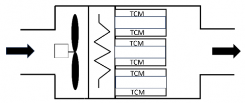
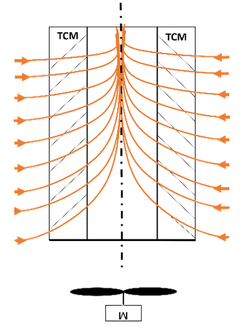
The prototype of the innovative TES system, based on TCM, is designed as an open-loop circuit. As shown in Figure 1, it comprises an inlet air section with forced ventilation, a thermal homogenization chamber incorporating a thermal battery, a TCMR, and an outlet air section.
The system operates with an airflow rate under ambient conditions. During the discharge mode, the use of the fan alone allows the ambient air humidity to come into contact with the TCM, where water vapor adsorption triggers an exothermic reaction (ΔH < 0), thereby promoting heat release. In the charging mode, the thermal battery is activated to dehydrate the TCM through an endothermic process (ΔH > 0), leading to the release of water vapor and the storage of thermal energy. To support the charging mode, renewable electrical energy from a photovoltaic plant can be used. Alternatively, electrical power from the grid can be utilised during the night when the cost is lower.
Figure 1. Open-loop SACER prototype scheme
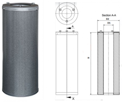
To efficiently harness the heat generated by the TCM, a modular system of multiple containers was developed to facilitate both the charging and discharging phases of the material within the reactor. As shown in Figure 2, each container features a cylindrical geometry, with internal and external diameters of 70 mm and 140 mm, respectively, and a length of 400 mm. The upper section of the container incorporates an air inlet, while the lower section is hermetically sealed.
Figure 2. TCM container and sectional view
The TCM was positioned within the annular region, with a volume of 4.61 × 10⁻³ m3, between the inner and outer cylindrical surfaces, respectively 8.79 × 10⁻² m2 and 0.1759 m2. The airflow enters axially through the central axis of the container. The perforated cylindrical surfaces facilitate the radial exit of the airflow, thereby enhancing convective heat and mass transfer during operation.
2.2 Selection of TCM composite
In this work, vermiculite [33] was selected as the host matrix for the hydrate salt solution. The raw vermiculite has a bulk density around 150 kg/m3. This choice is related to the high porosity of this raw material, which allows a greater quantity of salt to be stored inside its pores. CaCl2 was chosen due to its hygroscopic and thermal conductivity properties, as well as its reaction reversibility [34], availability, and low cost. To obtain a TCM composite, a saturated water-salt solution was prepared to impregnate the vermiculite through a vacuum process [35]. Subsequently, the material was subjected to thermal treatment. The TCM composite exhibits a bulk density around 360 kg/m3, with the salt content in the matrix reaching about 60% by mass. The total amount of TCM loaded into the container was 1.53 kg.
Prior to conducting tests with the experimental prototype, a study of thermal behaviour of the TCM container was carried out. This investigation offers an overview of the thermal performance of each container filled with TCM, with the aim of optimising the TCMR during discharge mode operation.
3.1 Experimental test rig
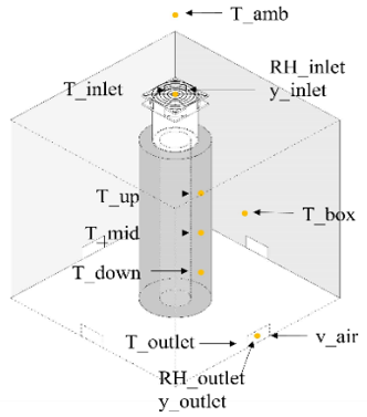
A dedicated test setup was employed to investigate the performance of the container during the discharge mode, focusing on the adsorption characteristics of TCM, temperature distribution, heat release, and the thermal power generation. To characterise the container’s behaviour under the conditions, measurements of temperatures, relative humidity (RH) and absolute humidity (AH), air flow rate and mass variations were recorded throughout the discharge process. To monitor the evolution of operational parameters during the heat release from the TCM and to assess the thermodynamic transformation of the air, multiple sensors were deployed. A control volume was defined using an enclosed box to replicate conditions similar to those of the experimental SACER prototype. As illustrated in Figure 3, the container was positioned at the center of the box, and the sensors were strategically installed in various locations to monitor changes in the physical state of the air between the inlet and the outlet sections. To reproduce the operational condition and facilitate the airflow along the container’s central axis, an electrical fan was mounted at the top of the TCM container. The fan, with a power consumption of 0.27 W, was powered by a current generator. The box enclosure featured a single air inlet and four air outlet sections. Temperature measurements were conducted using T-type thermocouples (TC) sensors installed at key positions within the set up. One TC was placed outside the box to measure ambient temperature (T_amb), one at the inlet (T_inlet) to capture temperature variation as a function of humidity, one within the box (T_box), and one at the outlet (T_outlet). Additionally, to perform a detailed thermal analysis of the TCM container surface, three TC sensors, denoted T_up, T_mid, and T_down, were installed at distinct axial positions along the outer surface of the cylindrical container. To assess the container’s adsorption capacity, sensors for RH and AH were positioned in the inlet (RH_inlet; y_inlet) and outlet (RH_outlet; y_outlet) sections, allowing the estimation of the vapor mass adsorbed by the TCM. Finally, an anemometer was integrated in the outlet section of the setup, to monitor the air flow velocity (v_air) during the test. To monitor the amount of water adsorbed by the TCM during the hydration process, the box containing the cartridge was placed on a precision balance. Additionally, a humidifier with a flow rate of 6.78 × 10⁻² kg/h was employed to modify the RH, AH, and temperature conditions in the inlet section of the test rig.
(a)
(b)
Figure 3. Experimental test rig. (a) Drawing of the experimental setup, (b) Laboratory setup
3.2 Boundary conditions
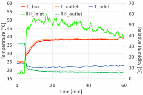
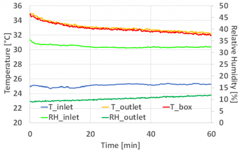
The first analysis was conducted under inlet air operating conditions characterised by an AH fluctuating around 8 gv/kgda, a temperature of 22℃, and a RH of approximately 50%. Using this boundary condition, the outlet temperature stabilises at an average value of approximately 37℃. Figure 4 shows that the temperature inside the control volume (T_box) is very close to the outlet temperature (T_outlet). The box, therefore, acts as a homogenisation chamber for the air. As a result of TCM’s hydration process, the outlet RH decreases during the discharge phase.
Figure 4. Outlet temperature and RH variation at 50% RH_inlet
As shown in Figure 5, under different inlet conditions, with an air temperature of approximately 25℃, a RH of around 32%, and an AH of about 7 gv/kgda, the outlet air conditions exhibit a trend consistent with that observed in the previous case. By reducing the inlet AH and RH conditions, a decrease in the outlet air temperature and an increase in the outlet RH can be observed. This result highlights that the heat released by the TCM is strongly influenced by the inlet conditions.
Figure 5. Outlet temperature and RH variation at 32% RH_inlet
Consequently, variations in these parameters lead to observable changes in the performance of the composite material contained within the system.
4.1 Container temperature distribution
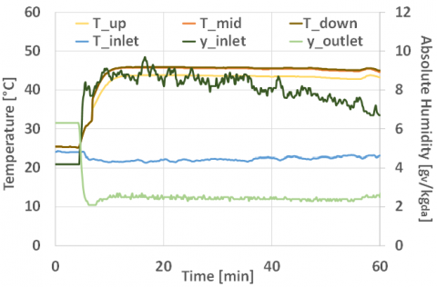
By analysing the temperature profile on the external surface of the container, where the three TC temperature sensors T_up, T_mid, and T_down, are located, it can be observed from Figure 6 and Figure 7 that the measured temperatures are very similar. This indicates that the hydration process during the TCM's discharge phase is homogeneous throughout the entire container.
Figure 6. Surface Temperature distribution of the TCM Container at air inlet condition 50% RH, 8gv/kgda AH
The trend of the outlet AH is directly correlated with the temperature variation occurring inside the container.
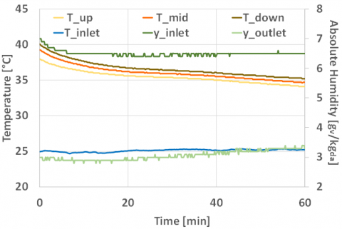
By modifying the boundary conditions of the inlet air, a behaviour similar to that previously discussed in this section can be observed. It can be concluded that the container is capable of establishing a homogeneous temperature distribution along its entire longitudinal section, which in turn indicates that the TCM undergoes uniform hydration.
Figure 7. Surface Temperature distribution of the TCM Container at air inlet condition of 30% RH, 6.5gv/kgda AH
4.2 Mass balance
The data collected from the sensors during the experimental test were used to perform a series of balances. First, a mass balance on the dry air flow rate within the experimental system was carried out. This was followed by a mass balance on the water vapor, and finally, by an energy balance.
In the design and optimisation process of TCM containers, a complete mass-energy coupling conservation model needs to be established. Based on the continuous medium assumption, the system mass conservation can be expressed by Eq. (1):
${{\dot{m}}_{vapor\_inlet}}={{\dot{m}}_{vapor\_ads}}+{{\dot{m}}_{vapor\_outlet}}$ (1)
where, ṁvapor_inlet and ṁvapor_outlet are the inlet and outlet vapor mass flow rates, respectively, and ṁvapor_ads is the mass flow rate of the adsorbed vapor, all expressed in gv/h.
The water vapor mass flow rate is calculated through real-time monitoring data using Eq. (2):
${{\dot{m}}_{vapor}}=y\cdot {{\dot{m}}_{da}}$ (2)
where, y is the AH corresponding to a given physical state measured by a high-precision humidity sensor gv/kgda; ṁda is the dry air mass flow rate calibrated by the mass flow meter kg/h.
The amount of TCM adsorption ṁvapor_ads was directly measured using an electronic balance (accuracy ±0.01 g), and its time derivative is shown in Eq. (3):
${{\dot{m}}_{vapor\_ads}}=\frac{d{{m}_{TCM}}\left( t \right)}{dt}$ (3)
The dry air mass flow rate ṁda is obtained according to Eq. (4).
${{\dot{m}}_{da}}={{\rho }_{air}}\cdot {{\dot{V}}_{da\_outlet}}={{\rho }_{air}}\cdot \sum\limits_{i=1}^{4}{{{A}_{outlet,i}}}\cdot {{v}_{da}}$ (4)
where, ρair is air density (1.2 kg/m³ at 22℃, standard conditions); V̇da_outlet is the calibrated volumetric flow rate based on an orifice-plate flowmeter; Aoutlet,i represents the cross-sectional area of the i-th outlet; vda stands for the real-time airflow velocity measured by an ultrasonic anemometer.
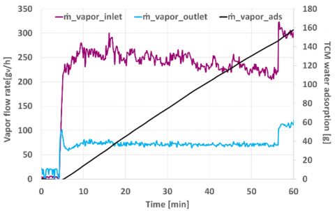
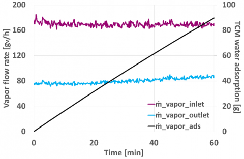
The theoretical validation based on the law of conservation of mass shows that the experimental system exhibits excellent equilibrium characteristics. As shown in Figure 8 and Table 1, the deviation of the inlet vapor mass flow rate ṁvapor_inlet (227.62 gv/h) from the sum of the adsorption capacity ṁvapor_ads (157.90 gv/h) and the outlet vapor mass flow rate ṁvapor_outlet (69.92 gv/h) is only 0.2 gv/h, with a relative error as low as 0.18%, which is much lower than the combined measurement uncertainty (±2.0%), confirming the tightness of the experimental setup and the reliability of the measurement system.
Figure 8. Variations of inlet and outlet air flow rates and variation of water mass adsorbed by the TCM at 50% RH
Table 1. Mass flow rate results
|
ṁvapor_inlet (gv/h) |
ṁvapor ads (gv/h) |
ṁvapor_outlet (gv/h) |
ṁbalance (gv/h) |
|
227.62 |
157.90 |
69.92 |
0.2 |
It is particularly noteworthy that the adsorption efficiency of 69.4% is in the optimal performance interval (60-75%) for salt-based TCM materials, which provides a solid mass balance basis for subsequent thermodynamic analysis. Figure 9 shows the mass balance corresponding to an air inlet relative humidity of approximately 30%.
Figure 9. Variations of inlet and outlet air flow rates and variation of water mass adsorbed by the TCM at 30% RH
4.3 Enthalpy balance
Following the completion of the mass balances, the energy balance was conducted. This required the calculation of the specific enthalpy associated with the different thermodynamic states characterizing the system under analysis. To evaluate the specific enthalpy J, that is, the enthalpy H per unit mass m, the following Eq. (5) was used:
$J=\frac{H}{{{m}_{da}}}={{c}_{p,a}}\cdot T+y\left[ r\left( T=0.01{}^\circ C \right)+{{c}_{p,v}}\cdot T \right]\cdots \left[ \frac{kJ}{k{{g}_{da}}} \right]$ (5)
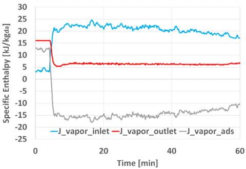
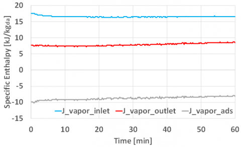
where, cp,a is the specific heat at constant pressure of the dry air flow kJ/kg·K, r is the latent heat of vaporisation, T is the temperature associated with that state, and cp,v is the specific heat of the water vapor kJ/kg·K. In the case under consideration, the equation was simplified by neglecting cp,a. Figure 10 illustrates the trends of the specific enthalpy of the inlet and outlet air states, and the enthalpy related to the heat released by the TCM within the system under investigation, for the cases of 50% RH and 30% RH.
(a)
(b)
Figure 10. Specific enthalpy balance at (a) 50% RH and (b) 30% RH
4.4 Thermal energy
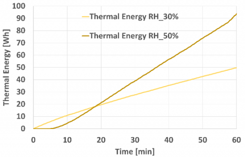
To evaluate the thermal energy over the one-hour test period, sensor data were utilised. First, the thermal power Q̇ was calculated under the two humidity conditions using the following Eq. (6). The average thermal power obtained with an inlet air RH of approximately 50% is 117.2 W, while at 30% RH it is 56.12 W. The specific power per unit mass is equal to 76.7 W/kgTCM in the first case and 36.67 W/kgTCM in the second. Considering a data acquisition interval of 9 seconds, the thermal energy values reported in Figure 11 correspond to this temporal resolution.
$\dot{Q}={{\dot{m}}_{da}}\cdot {{c}_{p,a}}\cdot \left( {{T}_{outlet}}-{{T}_{inlet}} \right)$ (6)
Referring to the first part of the test, in which the RH was approximately 50%, the thermal energy released by the TCM amounted to 97.7 Wh. In the second part of the test, where RH decreased to around 30%, the thermal energy released by the composite material was 50.51 Wh. This corresponds to a reduction of approximately 48.3% in thermal output. Based on this analysis, it can be concluded that the performance of the TCM is strongly influenced by the inlet boundary conditions, that is, by the thermodynamic state of the ambient air used during the process.
Figure 11. Thermal energy: 50% RH vs 30% RH
Under the given boundary conditions, the TCM did not operate at its full potential. At the end of the test, an analysis of the material's state revealed only partial hydration of the composite material relative to the total volume of the container. This result, which did not lead to the deliquescence of the material, indicates that, with the current configuration, using the inner section of the cylindrical container, it is only possible to exploit a portion of the thermal energy stored in the TCM under such conditions.
The test conducted shows the heat release from TCM through the adsorption of water from the ambient air humidity. So, during the discharge process, it is possible to exploit the thermal power of TCM using a free source coming from the air. So, this process uses a renewable source. According to the thermal performance represented in the previous chapter, the SACER TCM is capable of generating a temperature lift of approximately 16℃ in response to an incoming absolute humidity of around 8 g of water vapor per kilogram of dry air. During the test, the hydrated portion of the material represented only a small percentage of the total. This result indicates that the material can still undergo further hydration, as it remains well below the deliquescence threshold.
This study has been useful in guiding the redesign of the container layout within the TCMR system, with the aim of maximising thermal power output.
Figure 12. Future set up of the test rig
For future developments, according to Figure 12, it has been proposed to reverse the airflow direction through the container, such that the new inlet section corresponds to the outer surface of the cylinder, while the new outlet is positioned along the central axis. This configuration would increase the heat exchange surface area, thereby enhancing the degree of TCM hydration and consequently improving heat release.
The authors gratefully acknowledge the support of the ECHO project (Efficient Compact Modular Thermal Energy Storage System), funded by the European Union’s Horizon Europe research and innovation programme under Grant Agreement No. 101096257. Additional support was provided by the SACER project (Sviluppo e integrazione di Accumuli innovativi nelle Comunità Energetiche Rinnovabili), funded by the Emilia-Romagna Region through the High Technology Network and the Clust-ER Energy. The authors also thank all partners involved in the experimental activities and technical development associated with the test campaign.
|
A |
area, m2 |
|
AH |
absolute humidity |
|
CaCl2 |
calcium chloride |
|
CM |
composite material |
|
Cp |
specific heat, J. kg-1. K-1 |
|
$\Delta$ |
variation of a generic physical quantity |
|
EPBD |
energy performance of building directive |
|
ES |
energy storage |
|
EU |
european union |
|
H |
enthalpy, kJ |
|
J |
specific enthalpy, kJ. kg-1 |
|
m |
mass, kg |
|
ṁ |
mass flow rate, kg. h-1 |
|
PCM |
phase change material |
|
Q̇ |
thermal power kW |
|
r |
latent heat of vaporisation |
|
RE |
renewable energy |
|
RH |
relative humidity, % |
|
t |
time |
|
T |
temperature, ℃ |
|
TC |
thermocouple |
|
TCES |
thermochemical energy storage |
|
TCM |
thermochemical material |
|
TCMR |
thermochemical material reactor |
|
TES |
thermal energy storage |
|
v |
velocity, m. s-1 |
|
V̇ |
volumetric flow rate, m2. h-1 |
|
y |
absolute humidity, gv. kgda-1 |
|
Greek symbols |
|
|
ρ |
density, kg. m-3 |
|
Subscripts |
|
|
a |
air |
|
ads |
adsorbed |
|
da |
dry air |
|
v |
vapor |
[1] European Commission. (2019). Communication from the Commission. The European Green Deal. Brussels, Belgium. https://eur-lex.europa.eu/legal-content/EN/TXT/HTML/?uri=CELEX:52019DC0640, accessed on Jul. 20, 2025.
[2] European Commission. (2022). Communication from the commission to the european parliament, the european council, the council, the european economic and social committee and the committee of the regions. REPowerEU Plan. Brussels, Belgium. https://eur-lex.europa.eu/legal-content/EN/TXT/HTML/?uri=CELEX:52022DC0230, accessed on Jul. 20, 2025.
[3] European Parliament and Council of the European Union. (2024). Directive (EU) 2024/1275 of the European Parliament and of the Council on the energy performance of buildings. Official Journal of the European Union, L 127, 1–68. https://eur-lex.europa.eu/legal-content/EN/TXT/PDF/?uri=OJ:L_202401275, accessed on Jul. 20, 2025.
[4] Franco, A., Salza, P. (2011). A strategy for optimal penetration of intermittent renewables in complex energy systems based on techno-operational objectives. Renewable Energy, 36(2): 743-753. https://doi.org/10.1016/j.renene.2010.07.022
[5] Rodrigues, E.M.G., Godina, R., Santos, S.F., Bizuayehu, A.W., Contreras, J., Catalão, J.P.S. (2014). Energy storage systems supporting increased penetration of renewables in islanded systems. Energy, 75: 265-280. https://doi.org/10.1016/j.energy.2014.07.072
[6] Mitali, J., Dhinakaran, S., Mohamad, A.A. (2022). Energy storage systems: A review. Energy Storage and Saving, 1(3): 166-216. https://doi.org/10.1016/j.enss.2022.07.002
[7] Heier, J., Bales, C., Martin, V. (2015). Combining thermal energy storage with buildings -- a review. Renewable and Sustainable Energy Reviews, 42: 1305-1325. https://doi.org/10.1016/j.rser.2014.11.031
[8] Alva, G., Lin, Y., Fang, G. (2018). An overview of thermal energy storage systems. Energy, 144: 341-378. https://doi.org/10.1016/j.energy.2017.12.037
[9] Zhang, H., Baeyens, J., Cáceres, G., Degrève, J., Lv, Y. (2016). Thermal energy storage: Recent developments and practical aspects. Progress in Energy and Combustion Science, 53: 1-40. https://doi.org/10.1016/j.pecs.2015.10.003
[10] Li, G., Zheng, X. (2016). Thermal energy storage system integration forms for a sustainable future. Renewable and Sustainable Energy Reviews, 62: 736-757. https://doi.org/10.1016/j.rser.2016.04.076
[11] Sarbu, I., Sebarchievici, C. (2018). A comprehensive review of thermal energy storage. Sustainability, 10(1): 191. https://doi.org/10.3390/su10010191
[12] Jouhara, H., Żabnieńska-Góra, A., Khordehgah, N., Ahmad, D., Lipinski, T. (2020). Latent thermal energy storage technologies and applications: A review. International Journal of Thermofluids, 5-6: 100039. https://doi.org/10.1016/j.ijft.2020.100039
[13] Choure, B.K., Alam, T., Kumar, R. (2023). A review on heat transfer enhancement techniques for PCM based thermal energy storage system. Journal of Energy Storage, 72: 108161. https://doi.org/10.1016/j.est.2023.108161
[14] Baccega, E., Vallese, L., Bottarelli, M. (2025). Enhancement of thermal conductivity of paraffin PCM with metal foams. International Journal of Thermophysics, 46(3): 35. https://doi.org/10.1007/s10765-024-03500-6
[15] Clark, R.J., Mehrabadi, A., Farid, M. (2020). State of the art on salt hydrate thermochemical energy storage systems for use in building applications. Journal of Energy Storage, 27: 101145. https://doi.org/10.1016/j.est.2019.101145
[16] Aydin, D., Casey, S.P., Riffat, S. (2015). The latest advancements on thermochemical heat storage systems. Renewable and Sustainable Energy Reviews, 41: 356-367. https://doi.org/10.1016/j.rser.2014.08.054
[17] Ervin, G. (1977). Solar heat storage using chemical reactions. Journal of Solid State Chemistry, 22(1): 51-61. https://doi.org/10.1016/0022-4596(77)90188-8
[18] Pardo, P., Deydier, A., Anxionnaz-Minvielle, Z., Rougé, S., Cabassud, M., Cognet, P. (2014). A review on high temperature thermochemical heat energy storage. Renewable and Sustainable Energy Reviews, 32: 591-610. https://doi.org/10.1016/j.rser.2013.12.014
[19] Garg, H.P., Mullick, S.C., Bhargava, A.K. (1985). Solar Thermal Energy Storage. Springer Netherlands. https://doi.org/10.1007/978-94-009-5301-7
[20] Kant, K., Pitchumani, R. (2022). Advances and opportunities in thermochemical heat storage systems for buildings applications. Applied Energy, 321: 119299. https://doi.org/10.1016/j.apenergy.2022.119299
[21] Solé, A., Martorell, I., Cabeza, L.F. (2015). State of the art on gas--solid thermochemical energy storage systems and reactors for building applications. Renewable and Sustainable Energy Reviews, 47: 386-398. https://doi.org/10.1016/j.rser.2015.03.077
[22] Gordeeva, L.G., Aristov, Yu, I. (2012). Composites salt inside porous matrix for adsorption heat transformation: A current state-of-the-art and new trends. International Journal of Low-Carbon Technologies, 7(4): 288-302. https://doi.org/10.1093/ijlct/cts050
[23] Mikos-Nuszkiewicz, N., Furmański, P., Łapka, P. (2023). A mathematical model of charging and discharging processes in a thermochemical energy storage reactor using the hydrated potassium carbonate as a thermochemical material. Energy, 263: 125642. https://doi.org/10.1016/j.energy.2022.125642
[24] Chen, Z., Zhang, Y., Zhang, Y., Su, Y., Riffat, S. (2023). A study on vermiculite-based salt mixture composite materials for low-grade thermochemical adsorption heat storage. Energy, 278: 127986. https://doi.org/10.1016/j.energy.2023.127986
[25] Courbon, E., D'Ans, P., Permyakova, A., Skrylnyk, O., Steunou, N., Degrez, M., Frère, M. (2017). Further improvement of the synthesis of silica gel and CaCl2 composites: enhancement of energy storage density and stability over cycles for solar heat storage coupled with space heating applications. Solar Energy, 157: 532-541. https://doi.org/10.1016/j.solener.2017.08.034
[26] Zhao, Y.J., Wang, R.Z., Zhang, Y.N., Yu, N. (2016). Development of SrBr2 composite sorbents for a sorption thermal energy storage system to store low-temperature heat. Energy, 115: 129-139. https://doi.org/10.1016/j.energy.2016.09.013
[27] Zhu, D., Wu, H., Wang, S. (2006). Experimental study on composite silica gel supported CaCl2 sorbent for low grade heat storage. International Journal of Thermal Sciences, 45(8): 804-813. https://doi.org/10.1016/j.ijthermalsci.2005.10.009
[28] Ristić, A., Mal, S., Zabukovec Logar, N., Bérut, E., Bois, L., Outin, J., Ondarts, M., Le Pierrès, N., Serrano, Á., Durán, M., Santos, S., Palomo Del Barrio, E., Doppiu, S. (2024). Improving materials for compact thermal energy storage: Two case studies on tailor-made polyalcohol mixtures (PCMs) and composites of chlorides confined in gamma-alumina or silica-PEG (TCMs). ACS Applied Energy Materials, 7(20): 9242-9254. https://doi.org/10.1021/acsaem.4c01702
[29] Beaupere, N., Malley-Ernewein, A., Nahhas, T., Ginestet, S., Samson, G., Cyr, M. (2024). Experimental study of a thermochemical energy storage system operating at low temperature with ettringite-based materials. Solar Energy, 282: 112927. https://doi.org/10.1016/j.solener.2024.112927
[30] SACER Project. (2024). Sviluppo e integrazione di Accumuli innovativi nelle Comunità Energetiche Rinnovabili. https://www.sa-cer.it/, accessed on Jul. 20, 2025.
[31] ECHO Project. (2023). Efficient Compact Modular Thermal Energy Storage System 2023. https://echo-euproject.eu/, accessed on Jul. 20, 2025.
[32] Vallese, L., Lombardo, G., Menegazzo, D., Bordignon, S., De Carli, M., Barison, S., Agresti, F., Baccega, E., Bobbo, S., Fedele, L., Bottarelli, M. (2025). Evaluating the behaviour of a composite of CaCl2 and vermiculite for thermochemical adsorption energy storage: Experimental tests during the charging and discharging phases. Applied Thermal Engineering, 263: 125311. https://doi.org/10.1016/j.applthermaleng.2024.125311
[33] Zou, D., Yue, X., He, T., Ding, J., Ba, D. (2022). Experimental research on the preparation of K2CO3/expanded vermiculite composite energy storage material. Materials, 15(10): 3702. https://doi.org/10.3390/ma15103702
[34] Kuwata, K., Esaki, T., Yasuda, M., Matsuda, T., Kobayashi, N., Shiren, Y., Aman, Y. (2017). Durability of thermochemical heat storage demonstrated through long-term repetitive CaCl2/H2O reversible reactions. Journal of Renewable and Sustainable Energy, 9(2): 024102. https://doi.org/10.1063/1.4978351
[35] Zhang, Y., Chen, Z., Zhang, Y., Su, Y., Riffat, S. (2024). Parameter control in synthesis of vermiculite-CaCl2 composite materials for thermochemical adsorption heat storage. Energy, 291: 130478. https://doi.org/10.1016/j.energy.2024.130478