Hadeer Sattar Jaber*![]() | Basima Salman Khalaf
| Basima Salman Khalaf![]()
© 2025 The authors. This article is published by IIETA and is licensed under the CC BY 4.0 license (http://creativecommons.org/licenses/by/4.0/).
OPEN ACCESS
Evacuated tube solar collectors (ETSCs) are one of the most efficient solar thermal technologies, and they are high performance systems of solar thermal energy over a variety of environmental conditions. It is a comprehensive overview of the recent advancements in the design of ETSC, simulation, and its application in practice. The contributions are: (1) the introduction of phase change materials (PCMs) to increase heat storage during low-irradiance conditions, (2) the use of new selective nano-coatings to reduce radiative losses and maximize absorption efficiency, and (3) hybrid designs by using ETSCs with parabolic trough collectors to achieve higher thermal outputs. Moreover, the latest simulation tools, including CFD analysis and energy-exergy analysis, are mentioned and explained in terms of the optimization of collector designs. Other uses of ETSC that are reviewed in this review include domestic water heating, industrial process heat, solar air heating, and desalination, as well as the sustainability issues and the cost-benefit issues. The article is an integrated source of information for the researchers and engineers who seek to come up with the next generation ETSC systems that have a high level of efficiency, durability, and low costs.
ETSCs, solar thermal energy, heat pipe collectors, selective coatings, solar desalination, solar water heating, cost-benefit analysis
Since the 19th century, climate change and global warming have been nagging issues in the environmental arena [1]. Such phenomena are rather dangerous to human lives and health and lead to the development of new diseases and death rates because of the growing number of extreme weather conditions [2]. The increasing rate of climate change has caused nature to be unable to keep pace with the demand, and switching to alternative energy sources has become a matter of urgency [3].
Solar energy is the most popular and promising alternative to various other possibilities of renewable energy, like wind, hydro, and geothermal energies, among others. It is infinite, free, accessible, and unconstrained to use and is clean for the environment [4]. Solar energy falling on the surface of the earth and approximated at 120 × 105 W, has immeasurable potential; it would take only one day of solar energy reaching the earth to facilitate the energy requirement of the world for more than 20 years [5].
Besides, solar systems have less impact on the environment. They are convenient to install, are comparatively cost-effective to run, and are flexible in their usage [6]. Thermal conversion is one of the best harnessed ways of utilizing solar energy, whereby the solar radiations are converted into heat energy with the help of solar collectors.
At the center of any solar thermal energy system is the solar collector, which is a device designed to accept and transfer solar energy to a working fluid. These systems provide a dependable way of generating hot water and heating, besides generating power, both throughout residential areas and on an industrial scale. These collectors, especially ETSCs, have been developed and optimized to enhance the overall efficiency of solar thermal technologies as well as to increase the applicability of solar thermal technologies [7]. The heat energy is vital in ensuring the energy demands of various processes in the process industries. Due to this, it has led to the development of solar thermal energy systems as an appealing and sustainable source of heat in fulfilling different thermal processing requirements. Due to the large potential of solar thermal systems substituting conventional energy sources based on fossils, small-scale uses have great potential in space heating, cooling, domestic water heating, industrial process heating, and power generation at least [8].
A solar collector is the fundamental element of any given solar thermal energy conversion system and plays the role of converting the incoming solar radiation into thermal energy [9]. These collectors act as heat exchangers, receiving heat in the form of solar radiation and conveying the heat acquired to a working fluid, usually water, air, or special thermal fluids [10].
The conventional solar collectors are largely categorized into two, i.e., the non-concentrating solar collector and the concentrating solar collector. The optical components on the collectors, called collectors, are used of optical components, either mirrors or lens in concentrate solar radiation on a small proportion of the receiver and may be referred to as imaging and non-imaging according to whether the image sun is concentrated [11]. Conversely, the non-concentrating collectors are mounted and absorb the solar rays using the same surface area in the same surface. These systems are non-moveable ones that do not track the sun.
Evacuated tube solar collectors (ETSCs) are highly efficient since they have high thermo-performance and thus are common amongst non-concentrating collectors [12]. ETSCs are straightforward gadgets that gather solar power and then pass this on to a working fluid, most commonly air or water [13]; such systems can be functional at temperatures that exceed 50℃, particularly when selective coatings are used in conjunction with convection suppressors that are capable of improving heat performance [14].
Energy is available regardless of the weather during cloudy days or the night because the solar energy absorbed by ETSCs during the day can be stored in thermal energy storage tanks or can be released to an immediate load. When compared to the flat-plate collectors, the ETSCs have a better performance mainly at high operating temperatures because of the presence of the two layers of glass envelope that form a vacuum insulation barrier. By substantially decreasing the conductive and convective heat losses, this vacuum is an effective means of placing some technical significance on the emissivity values of both simple and modified black bodies [15, 16].
Furthermore, the use of advanced selective coatings-such as aluminum-nickel alloys-on the absorber tube enhances solar absorption while minimizing thermal re-radiation, contributing to improved system efficiency [17].
Experimental studies also play a central role in the knowledge of the dynamic nature of the ETSCs under various environmental conditions. Sharma and Diaz [18] proposed and tested the experimental, steady, and transient thermal response of an evacuated-tube solar collector that integrates mini-channels, using a performance model. Their findings revealed that the redesign technique resulted in high thermal conductance and a better response time, which is vital to real-time energy demand usage.
Besides, the comparison between the ETSCs and other solar thermal technologies (including flat plate collectors (FPCs)) is usually simulated but not grounded. As an example, Kalogirou [19] compared the water-in-glass ETSCs with flat plates under the same operating conditions. Their experimental data showed the superiority of higher temperatures of ETSCs compared to FPCs in environments of colder climates with better insulation and less heat loss.
The summary of what is known in ETSC design improvements is:
•Several geometries have been experimented with absorber tubes to increase the surface area of heat transfer (e.g., Model II was the most efficient at large incidence angles of the Sun) [20].
•Thermal emissivity can be minimized by selective coating (e.g., aluminum-nickel alloys) and increased absorption can be achieved [21].
•The system enhanced the thermal conductance and reliability of heat pipes and U-pipes in different environmental conditions [22].
•New applications of phase change materials (PCMs) enhance thermal storage and extend heat supply at times of low sunshine [23, 24].
Moreover, the gaps are:
•Long-term limited literature of data on nanocoated tubes and PCM-integrated designs.
•Inconsistency in the ideal tube geometries in various climatic conditions.
•Some comparative research on material degradation is limited.
The summary of what is known in methods of performance optimization through simulation are:
•Much more common CFDF models and energy-exergy analysis are used to model the thermal performance of ETSC in dynamic conditions [9, 10].
•Transient modeling assists in forecasting instantaneous collector conduct and also maximizing heat pipe designs [18].
•Hybrid ETSC-parabolic trough designs have been modeled in 3D with the SolidWorks or ANSYS software to test [25].
In addition, the gaps are:
•Not many models combine dust deposition, degradation due to the effect of age, or climate variability.
•Absence of simulation tools/environment benchmarking.
•Little real time verification of simulations with experimental data.
A summary of what’s known in application and system integration in the real world is:
•ETSCs find wide application in solar water heating, solar air heating, solar cooking as well as desalination in the remote localities [24, 26, 27].
•ETSCs-CPCs or PTCs hybrid systems are found to be better in terms of thermal output in industries [28].
•It is confirmed that ETSCs are superior to FPCs in cold and diffuse-light terms, particularly when the surface is vacuum-insulated and coated [29].
Moreover, the gaps are:
•Absence of integration research in smart grid or urban district heating settings.
•There are limited techno-economic evaluations of ETSC based systems and PV+thermal hybrids on a long-term basis payback.
•The strategies of regional deployment and maintenance logistics are underreported.
The objectives of the present review are the following critical evaluation and synthesis of recent developments in the area of evacuated tube solar collector (ETSC) technology to achieve the following objectives:
1. To examine the effect of the various design configurations (e.g., heat pipe, U-pipe, and water-in-glass) of the ETSC on thermal efficiency and heat retention at different climatic conditions.
2. To investigate the efficiency of advanced materials, including nano-selective coating and phase change materials (PCMs) to enhance solar absorption, minimize heat losses, and storage abilities of energy.
3. To assess and compare simulation techniques, such as computational fluid dynamics (CFD) and energy-exergy analysis, in simulating and optimizing the work of ETSC.
4. To determine the applicability and effectiveness of the ETSCs in practice, especially in the process heating of industries, domestic hot water, and solar desalination and solar drying.
5. To determine what gaps in research and technological constraints are present in the field of ETSC implementation and outline the ways forward in the future in reducing costs, sustainability and integrating hybrid systems.
ETSCs are widely used due to their ability to achieve higher operating temperatures (typically ranging from 50℃ to 130℃) compared to conventional flat-plate collectors. These collectors consist of vacuum-sealed glass tubes, which provide excellent thermal insulation by significantly minimizing convective and conductive heat losses through the absence of air within the tube. A key component commonly integrated into ETSCs is the barium getter, which plays a dual role: maintaining the vacuum inside the tube and serving as a visual indicator of vacuum integrity. The barium material initially appears silver in color but undergoes a visible color change in the presence of air, thereby providing a clear indication of vacuum loss or malfunction within the tube system. This diagnostic feature enables easy identification of defective tubes and ensures system reliability and performance stability [22].
The ETSCs are more efficient and inexpensive than the latter. They are cylindrical in shape to enable them to collect the solar radiation the whole day, making them more effective in various solar applications. As a result, they are widely used due to their superior performance and productivity.
Every evacuated tube is constructed of two glass pipes, an inner and an outer tube. The inner tube has a selective coating that boosts solar absorption, and the outer one is transparent to enable the sunlight to go through. Solar radiations are used to heat up the inner tube, and by fusing the two tubes together at the top of the tubes, the space between them is evacuated to form a vacuum. This vacuum significantly reduces heat loss due to conduction and convection, resulting in more efficient energy collection than flat plate collectors [30]. A wide range of technologies exists for collecting solar radiation, among which the ETSC is preferred due to its superior performance. The constructional details of an evacuated tube are illustrated in Figure 2. Compared to flat-plate collectors (FPC), ETSCs offer better efficiency in high-temperature operations because the vacuum envelope surrounding the absorber surface significantly reduces convective heat losses.
Initially developed by Speyer [22], the initial commercial success of ETSCs was hampered because of the costs to manufacture the complex heat extraction manifolds made of metal and the technical problem of liquid-tight sealing of glasswork or joints at the ends of the tubes. Nevertheless, this ETSC market expanded dramatically when cheap sputter coating machines became available, allowing selective coating of nominally flat surfaces of glass absorbers in all-glass tubes. Additional developments came with research into the possibilities of different heat extraction manifold designs of single-ended evacuated tubes, first with Window [13].
•Evacuated tube solar collectors have three common types [31]:
a. A water-in-glass ETSC,
b. To decrease the cost, (b) U-type ETSC [32].
c. ETSC with heat pipe.
The major purpose of these collectors is to absorb radiation that comes partly in the form of solar energy and then shift the consumed heat to an internal heat pipe. Subsequently, a heat pipe to its end, which is in thermal connection with a secondary medium, usually water or oil, therefore heating the secondary medium, carries the energy.
The evacuated tube is usually made of two concentric glass tubes with a vacuum between the tubes. This vacuum creates an insulator that results in substantial reductions in loss of heat in terms of convection and conduction.
One of the most popular solar thermal technologies that is used is the evacuated tube solar collector (ETSC), which is deemed the most efficient non-concentrating collector [33]. They need comparatively smaller spaces to install them, and they can work well even when weather conditions are cloudy, cold, and windy [34]. The paper will give an overview of the latest contributions and developments in evacuated tube solar collectors.
An evacuated tube is made up of a cylinder made of glass where the inside surface has been made solar-absorbing and then coated selectively and contained in a vacuum [21]. These selective paints are said to optimize absorption of solar radiation and minimize heat emissivity, making them achieve maximum thermal performance of the collector [25].
Various studies on ETSCs have been carried out with specific emphasis on ascertaining the thermal efficiency. An example is that some studies have experimentally tested the performance of ETSCs that have the design of heat pipes. Still, other researchers have utilized numerical approaches to analyze the impact of the usage of phase-change materials (PCMs) on the system enhancement in terms of the storage and transfer of heat. The literature also has comprehensive reviews regarding ETSCs. Furthermore, scholars have investigated hybrid combinations, e.g., evacuated tube collectors with parabolic trough collectors, to improve the total efficiency system. Elarem et al. [23] conducted a numerical investigation using SolidWorks to model ETSC to act as a receiver on a parabolic solar concentrator. The paper presented set out to assess the thermodynamic performance of the hybrid system and study the heat transfer mechanisms inside the collector. The simulated outcomes revealed that the system has the potential to accommodate a high thermal efficiency of about 75 percent concerning the elevated temperatures. In addition, thermal insulation was determined as effective (the heat loss coefficient was between 0.6 and 1.3 W/m·K, thus resulting in minimal energy losses [34].
Other studies have already shown that the layout geometries of the ETSCs have a considerable contribution to the thermal performance of these modules. The most common aspects of these configurations can be classified as four, namely geometry of the absorber, modification of the flow passage changes, number of passes in the flow, and incorporation of the outside aids, as revealed in the numerous experiments and simulation results.
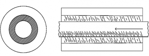
The ETSC is composed of an envelope, an absorber tube, a selective coating on the outer absorber tube, and the inner part which is an internal adapter through which thermal energy will transfer (Figure 1) [34].
Figure 1. Novinger model of solar evacuated tube [34]
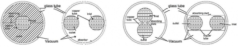
Reflectors may also be added to the lower half of the outer envelope tube [20]. The evacuated tube solar collector was designed with four absorber tube geometry variations to identify the optimum suitable shape that can maximize performance in both experimental and numerical patterns. The results indicated that evacuated tube collectors perform better when they have a larger absorbing surface area Figure 2. Among the models tested, Model II, which featured an increased absorbing surface, demonstrated the highest efficiency, particularly at higher solar incidence angles [26].
Figure 2. Four models with injection differences in terms of shape uptake [20]
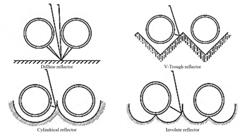
Various types of reflectors were employed in combination with an absorber plate to capture the total solar irradiation. Among these, diffuse reflectors with plain surfaces offer the lowest cost but also exhibit the lowest performance Figure 3. In contrast, V-trough and cylindrical reflectors are more commonly used due to their superior performance and ease of fabrication.
Figure 3. Different reflectors [26]
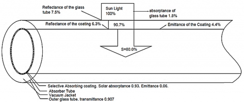
In spite of these improvements, both optical and thermal losses continue to occur in ETSCs. Optical losses occur because of the reflectance and emittance properties of materials employed Figure 4, whereas convection and conduction cause the thermal loss by transferring their heat to the surrounding atmosphere.
Figure 4. The evacuated tubes' optical losses [35]
The goal of an optimization process is an ideal evacuated tube solar collector that makes use of the entire possible incoming irradiance with minimum thermal and optical losses. A hard, selective coating with high absorbance and low emissivity is used to minimize optical losses, and reflectors are designed accordingly. In addition, to reduce optical loss further, the glass cover is applied, and then thermal loss is minimized by creating a vacuum between the absorber and the glass cover.
Among the various heat extraction methods, the water-in-glass type is considered the most cost-effective and simplest for domestic water heating applications [36]. For cooking purposes, particularly during cloudy conditions or at night, evacuated tubes incorporating heat pipes with phase change materials (PCMs) are commonly used [24]. These materials enable continued heat transfer even in the absence of sunlight, maintaining the collector's performance under varying weather conditions.
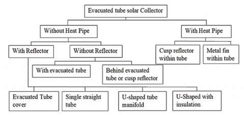
ETSC has many designs found in the literature. There are three subdivisions of them that are shown in Figure 5 [27].
Figure 5. Type of ETSC [19]
5.1 ETSC
ETSCs are systems of several layers of parallel and transparent glass tubes with the help of a frame. These tubes are generally 2.5 cm to 7.5 cm in diameter and 1.5 m to 2.4 m in length, depending on the manufacturer. These tubes have an outer layer made of thick glass and an inner layer made of low-thickness glass. The inner tube contains a selective coating capable of absorbing the solar radiation as much as possible, causing minimal thermal losses. Normally, these tubes are constructed out of soda-lime glass that also provides high solar transmittance and reasonable thermal resistance properties [36].
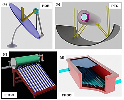
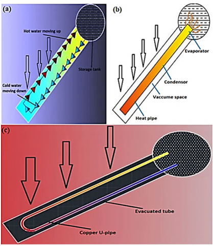
The system can be called evacuated, as between the inner and outer tubes, as shown in a schematic manner in Figure 6, a vacuum is created. This vacuum can be a good insulator and reduce conduction and convective acquisition of heat to ambient surroundings a great deal. The main categories of ETSCs currently known are all-glass, heat pipe, and U-pipe heat collectors that are mainly distinguished by their method of extracting heat, as illustrated in Figures 7(a)-(c), respectively.
Figure 6. (a) PDR, (b) PTC, (c) evacuated tube, and (d) flat plate [37]
Figure 7. (a) All glass ETSC, (b) Heat pipe ETSC, and (c) U-pipe ETSC [37]
5.1.1 All-glass ETSC
The all-glass ETSC has a design just as its name suggests, which means that it is made of glass tubes exclusive of other substances. To reduce the effect of heat loss and to increase thermal efficiency, the tubes are evacuated. The water present in the bottom of the storage tank enters the glass tubes into which the solar radiation heat is applied. Since the water gains heat, it becomes less dense and thus starts rising to the top of the tank by itself. At the same time, cooler water of the tank sinks to the tubes to warm.
This continuous circulation of water is driven by the thermosyphon effect, a natural convection process that requires no external pump. Due to this passive circulation mechanism, the system is also referred to as a thermosyphon water heater. The flow of hot and cold water within the tubes is often illustrated using red arrows to denote the movement direction.
5.1.2 Heat pipe ETSC
A heat pipe is inserted in each of the evacuated glass tubes in a heat pipe ETSC and normally encased by an aluminum fin. The solar radiation is admitted through the evacuated tube, and it heats the fin, producing an increase in temperature. Heat is transferred through conduction and convection to the heat pipe by the aluminum fin.
The amount of working fluid (refrigerant) in the heat pipe is not much, and the pressure is low. The heat in the evaporator of the heat pipe is absorbed by the heat pipe, hence, the heat pipe fluid starts to evaporate when heated. The resultant vapor drives towards the condenser portion at the uppermost end of heat pipe where heat is lost in latent form to the water stored in the manifold or the tank. In doing so, some of the heat is transferred and the vapor is condensed once again to a liquid once again returning to the evaporator section by means of gravity and the cycle is completed.
This closed-loop phase change process enables efficient thermal energy transfer from the solar collector to the water storage system, with minimal thermal resistance and no direct contact between the water and the heat pipe fluid.
5.1.3 U-pipe ETSC
U-pipe ETCs, also known as direct flow evacuated tube collectors, utilize a pair of copper pipes arranged in a U-shaped configuration inside each evacuated tube. A pipe is used as the inlet (flow) pipe; another one as the outlet (return) pipe. The bottom end of the tube is curved into a closed U, starting with the bending and brazing together of these pipes.
A metal fin is generally inserted around the U-pipe in the evacuated tube to increase the rate of heat flow. As solar radiation enters the glass tube, it gets to falls on the interior surface of the tube and thus heats the metal fin. The heat is then transferred to the U-pipe and finally to the working liquid (which is most of the time a mixture of water and glycol) flowing through it.
This configuration allows for direct thermal exchange between the solar-heated components and the working fluid, resulting in efficient heat transfer. The system operates under forced circulation, often requiring a pump, unlike thermosyphon systems.
Solar thermal collectors are systems designed to convert solar heat into usable energy. Among these, systems utilizing ETC are particularly efficient and versatile. Their applications span various domains, including:
6.1 Domestic water heating
Solar water heating systems in households extensively employ ETSCs, which have high efficiency even in cold weather and during cloudy weather.
Performance Example: A water-in-glass ETSC installed in Sydney, Australia by Budihardjo and Morrison [29] has the following outcomes: Average daily efficiency: 61-68%. Increase in the temperature of water: 20-45℃, but again it depends on the amount of sunshine. System payback period is 5-7 years old.
It is noted in the article of Budihardjo and Morrison [29] that companies make efforts to avoid emphasizing stressful and negative factors, as this will reinforce poor performance and bring about negative perceptions.
6.2 Solar drying (agricultural products)
Example: A solar dryer with the help of ETSC, which was used to dry chilies in a study by Tiwari and Tiwari [27] demonstrated: Drying period was 30-40% less than sun drying in nature. Efficiency of average collector: 52 per cent. Return on investment (ROI): 2.5 years.
Later, the authors also clarify what makes people want to produce electricity through photovoltaic methods.
6.3 Solar desalination
Multi-effect distillation (MED) and solar stills are the technologies that require the heat taken care of by ETSCs in off-grid areas with limited water supplies.
Case Study: Sharma et al. [24] combined ETSCs and a solar still system: Performing drinking water: 3.2-4.5 L/m2/day. Thermal efficiency of ETSC: 63% Savings in the operational expenses compared to diesel-powered desalination: > 70%.
6.4 Industrial process heat
Textile, dairy, and chemical industries use ETSCs in cases when medium-grade heat (600 to 150℃) is required.
Performance Example: ETSC in a textile factory in India pilot [38]: Supplied hot water at 90-110℃. Reduced LPG consumption by 38%. Annual savings in cost: USD 3200/100 m2 collector area. Payback period: 3.5 years.
Table 1 shows the cost-effectiveness overview.
Table 1. Cost-effectiveness overview
|
Application |
Efficiency |
Typical ROI |
Notes |
|
Residential water heating |
60-70% |
5-7 years |
effective in temperate climates |
|
Solar drying |
~50% |
2-3 years |
boosts productivity for small farmers |
|
Desalination |
60-65% |
6-8 years |
sustainable option for remote communities |
|
Industrial heating |
65-75% |
3-4 years |
strong potential where LPG/diesel is costly |
7.1 Advantage
1. Enhanced solar energy absorption
The circular design of the tubes ensures maximum solar energy absorption by maintaining the solar rays at a vertical angle throughout the day.
2. Durability and ease of maintenance
Evacuated tubes are robust, long-lasting, and easy to maintain.
If a tube breaks, it can be replaced individually without the need to replace the entire manifold.
3. Minimized heat loss
A vacuum is created inside the solar tube by removing air.
This vacuum significantly reduces heat loss through convection and conduction within the tube, enhancing overall efficiency [29].
7.2 Disadvantage
1. Year-Round boiling capability
With their high solar radiation absorption performance, solar tube collectors are capable of boiling water throughout the year, regardless of seasonal variations.
2. Maintenance and cost
Solar hot water systems and evacuated tube systems must get constant maintenance to perform and give optimum results.
However, ETC systems are generally more expensive than other solar hot water systems due to their advanced design and efficiency [29].
Justification of thermodynamics: The use of coatings and reflectors to enhance the efficiency of ETSC.
1. Selective coatings: radiative loss of heat
The absorber coating (e.g., aluminum-nickel, black chrome) placed on the surface is selective to have:
High solar absorptivity ($\alpha$ ≈ 0.95-0.98): Optimizes the intake of the shortwave sunshine.
Low thermal emissivity ($\varepsilon$ ≈ 0.05-0.15): It reduces re-radiation of the longwave infrared heat to the environment.
Thermodynamic Basis:
Stefan-Boltzmann law radiative heat loss is ruled by:
$q_{rad}=\varepsilon \sigma A\left(T_s^4-T_{a m b}^4\right)$ (1)
where,
$q_{rad}$: radiative heat loss
$\varepsilon$: emissivity of the surface
$\sigma$: Stefan-Boltzmann constant
A: surface area
Ts: surface temperature
Tamb: ambient temperature
2. Reflectors: improved incident energy gathering
V-trough or CPC (compound parabolic concentrator) reflectors bend off-axis sun radiation onto the absorber tube raising the optical concentration factor C.
Thermodynamic Effect:
A larger incident energy results in a large heat flux (q"):
$\begin{aligned} & q^{\prime \prime}=G_{e f f} \cdot \alpha \\ & G_{e f f}=C \cdot G\end{aligned}$ (2)
where,
G: global solar irradiance
Geff: effective irradiance after concentration
$\alpha$: absorptivity
By increasing Geff through optical concentration, reflectors raise the temperature differential $\Delta T$ between the absorber and the working fluid, enhancing convectiondriven heat transfer:
$q_{c o n v}=h A \Delta T$ (3)
where, h is the convective heat transfer coefficient.
Radiative losses are minimized through selective coating by minimizing emissivity. The reflectors enhance the amount of solar input absorbed by augmenting the effective irradiance on the absorber surface. Both enhance heat gain and losses in the system, thereby improving the first law efficiency ($\eta_{t h}$) of the system:
$\eta_{t h}=\frac{Q_{ {useful }}}{Q_{ {incident }}}=\frac{m \cdot c_p \cdot \Delta T}{G \cdot A}$ (4)
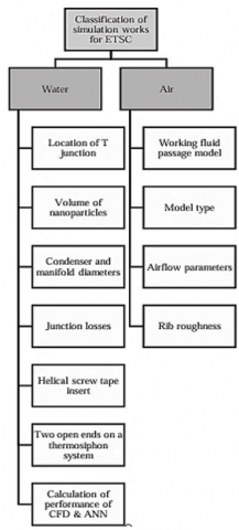
Simulation studies on ETSCs can be classified according to several criteria, including the modeling approach, purpose of the simulation, scale of analysis, and tools used. Figure 8 outlines the major categories.
Figure 8. Classification of simulation works for ETSCs
The environmental impact of ETSCs is one of the essential elements to be considered when reviewing long-term values and viability of evacuated tube solar collectors as a long-term renewable energy alternative. Although ETSCs serve as an effective alternative source of energy as compared to conventional energy sources, as they use solar energy, the production and the composition of their materials, as well as disposal at end of life, will influence the environment. An integrated picture of their environmental impact is needed so that the advantages of solar thermal energy can be ensured [39].
The contents of the materials that are in the structure of ETSCs make up one of the major aspects of environmental repercussions. The key materials are glass tubes, metal heat pipes, and selective coatings, most of which are non-renewable resources. Glass is an energy-intensive product, but it is a recyclable product, and even though such a product is very much in a recyclable state, the total amount of energy used during the manufacturing process of the glass is massive. Moreover, the coatings that are deposited on the absorptive surfaces usually comprise metals like copper or aluminum, which are harmful to the environment unless observed when recycling them [40].
Secondly, ETSC manufacturing consists of a variety of procedures, such as processing the glass tubes, coating, and assembling heat pipes. Production of all these stages entails emissions and waste by-products, and they define the overall environmental impact. Such an example can be considered when giant amounts of heat and electricity are consumed to produce evacuated tubes, and such energy often is nonrenewable, depending on the energy grid of a specific region. One of the biggest potential areas of improvement is reducing the amount of energy used and the quantity of waste produced in the manufacturing process to decrease the environmental burden caused by ETSCs [28].
One of the most pronounced environmental issues is the possibility of material degradation and waste at the end of the life cycle of an ETSC. Glass can be recycled, whereas removal and recycling of components like metal heat pipes and coatings are more complex. The factor that may further complicate recycling is the factor of having specialized coatings; this needs additional ways of processing or disposing of it to eliminate contamination. Other studies have advised that the environmental impact of ETSCs during their lifetime could be lowered by using more eco-friendly materials, e.g., recyclable polymers or biodegradable coatings [28].
Further, the sustainability of ETSCs in the long term is also pegged on their efficiency in the end. With age, the thermal performance of ETSCs may decline through material fatigue, corrosion of their surface, or through the buildup of dirt or dust on the glass tubes in them. ETSCs are fairly low-maintenance but may pale in certain environmental conditions, such as poor air quality or extreme weather conditions. When the working of the system becomes less effective, maintenance, repairing, or even replacement of this system may be necessary and so in extra costs to the environment [41].
Lastly, ETSCs' carbon footprint can be measured with the comparison of their ecological consequences with other energy technologies. A study by Kalogirou [11] showed that the carbon savings during the cycle of the solar thermal systems, inclusive of ETSCs, might exceed their environmental costs throughout their life cycle, particularly in cases when the energy required to operate and construct is using renewable sources. Nevertheless, this needs further research, especially in places where the grid electricity mostly relies on the use of fossil fuels.
Finally, the ETSCs are good for the environment, considering that they utilize solar energy, but the state of the environment during their production, material, and disposal should be looked at. Further developments within the ETSC technology must aim at working with sustainable materials, optimizing production, and maximizing the friendly nature of the system to the environment, which includes production up to the disposal period [28].
ETSCs' economic feasibility and cost-effectiveness are pertinent when activity is introduced to the representation of the cost of the market and performance of other solar thermal technologies. Although ETSCs have proved to be more efficient, especially when operating at higher temperatures, their efficiency may be constrained by the high expenditure to acquire them and the complexity during installation. These need to be balanced with operational savings of the long-term operations. Among the major benefits of ETSCs is their increased thermal performance, particularly in cold climate zones or unreliable sunlight. In a number of studies, ETSCs have proved more efficient than FPCs because vacuum insulation dramatically decreases heat loss. Nevertheless, there is a cost implication of this better performance enhancement; ETSCs are costly to make and install because of their complicated design and materials [38].
On cost-effectiveness, however, the upfront cost of ETSCs tends to be high, factoring in the component costs of the tubes as well as other costs of installation and the infrastructure required to mount and connect to the system. In areas that experience much sunlight and relatively warmer ambient temperatures, the use of the flat-plate collector can be a better approach because it is cheaper and easier to install. As an example, Budihardjo and Morrison [29] discovered that the original cost of FPCs is much cheaper, yet in colder climates, FPC performance degrades greatly, as opposed to ETSCs that perform very well. Their comparison, in which both technologies were put in quite similar conditions, showed that, although ETSCs might deliver more promising performance in such areas, ETSCs tend to have relatively long payback periods when compared to FPCs.
Furthermore, it is also significant to mention the operating costs of ETSCs. With their sealed design, they are less demanding to maintain than other forms of collectors, but since their parts are usually complex and the delicate glassware is easily damaged by mechanical impact, it can test repair limits and its cost. Kalogirou [11], in a study on ETSCs, noted that such systems have a competitive life cycle cost to FPC and can achieve a competitive payback on investment (ROI), but a higher up-front cost may increase payback on investment (ROI) unless the system is implemented in locations with high heating loads.
A more thorough cost-benefit analysis of ETSCs needs to be done to determine how cost-effective ETSCs are, with consideration of factors like how long a system lasts, how expensive it would be to maintain, what sort of government incentives exist, and how much energy it would save based on location climate. It would also be useful to analyze such costs in terms of the long-term savings of ETSCs against the other renewable energy technologies like photovoltaic (PV) systems that have made major cost reductions over recent years [38].
Another element of the question concerning the cost-effectiveness is the scalability of ETSCs. In cases of large-scale industrial applications, ETSCs may have substantial advantages over other methods of furnishing high-temperature heat, though initial costs and the amount of space taken up may be constraining factors in some locales. Conversely, small-scale domestic needs can take advantage of the cheaper initial cost of the flat-plate systems, as they normally do not require a large energy requirement [38].
Future studies in the area of ETSCs ought to be aimed at optimizing their manufacturing processes to lower the costs of producing them and mining alternative materials capable of comparable or better thermal performance and at lower total costs. There are also possibilities to build ETSCs into hybrid or district heating systems, which might offer lower cost solutions via spreading the high initial investment over more users [38].
Soiling or dirt accumulation on photovoltaic panels is a major cause of reduced efficacy and electricity production of the panel. 75 publications on soiling detection methods that were found in the Scopus database are reviewed. It reveals the existing gaps in the research with no strong detection systems and the necessity to engage such technologies as artificial intelligence. The results show that deep learning and sophisticated sensors could be used to enhance the accuracy of detection. The suggestions for future research would comprise the creation of new tools of inspection and cleaning systems to increase efficiency and minimize expenditures [42]. Another work considers how the velocity (2, 4, and 6 m/s) of the inlet tube influences the behavior of a mixture of water and ethylene glycol in an engine oil heat exchanger. The most significant ones are the drop of the oil viscosity to 0.021 Pa.s at the flow rate of 2 m/s and 0.015 at the flow rate of 6 m/s, which showed the relationship between thermal properties and flow rate. Further, the pressure drop has a dependence on inlet velocity that is 0.45 Pa and 0.92 Pa at 2 m/s and 6 m/s, respectively. Velocity profiles indicate that the maximum flow velocities are 2.3 m/s at the sharply curved walls and 1.7 m/s at the inner wall, and that the heat transfer coefficient is 500 W/m2/K at 2 m/s, and it increases to 950 W/m2/K at 6m/s. The heat transfer rate becomes much better and it was increased to 15 kW at 2 m/s and 35 kW at 6 m/s, with the overall performance of 70 percent as the inlet velocity increases and pointing to better convective heat transfer and uniformity of the flow [43]. The attempt to provide solar and wind energy within grid-connected electric vehicle charging stations (EVCSs) allows achieving sustainable mobility by reducing emissions of greenhouse gases and reliance on fossil fuels. This paper is a review of developments in hybrid solar-wind systems, with respect to the optimization of the design, energy management, and feasibility. A very stringent selection of studies was done following PRISMA rules and using major databases. Results indicate that these renewable-based EVCSs would be able to improve reliability and cost-effectiveness and decrease emissions. Such solutions as AI and optimization algorithms aid operation efficiency and promote vehicle-to-grid (V2G) capabilities. Nevertheless, scaling and practical verification are still a challenge. In the future, investigations must be focused on the field demonstrations in the long-term, as well as the potential of existing practical business models with V2G to encourage the mass adoption [44]. Another paper explains the relevance of fresh drinkable water and analyzes a new design of a solar still that will enhance thermal efficiency. The design has stepped types and magnets, which make it 39.329 and 31.745 more productive than the traditional models, respectively. The real performance showed that 136.2 using magnets further enhanced the productivity. The article has noted that solar evaporation is an efficient passive method of desalination; however, there are issues with rate of freshwater production and efficiency of evaporators, in terms of material characteristics of evaporators and temperature variations required to achieve maximum efficiency in evaporation. Even though people have made progress in connecting solar absorbers and photothermal materials, they still have a gap in the successful solar evaporation through uncomplicated fabrication methods [45]. There is a rising scarcity of freshwater in the world; more so, in dry areas, a feat unattainable when considering transport of drinkable water to places such as islands, where it is expensive. The 21st century ought to emphasize enhancing water purification through renewable energy, especially solar energy in desalination, since it has the potential to increase the equipment lifespan, reduce the costs, and also reduce the environmental damage. It examined different passive and active solar stills with special emphasis on vacuum tube solar stills as the most effective. It also explores the ways of cooling the glass cover and niduses that affect the productivity of solar stills with reference to addressing the desperate demand for freshwater and solar energy in the purification processes [46].
10.1 Practical benefits and impact of ETSCs
1. Saving of economies to industries: ETSCs provide medium temperatures (50-150℃) and this makes them suitable in the operations of industrial operations such as textile dyeing, food drying, or dairy pasteurization which rely on fossil fuels such as diesel or LPG.
Textile plant, India case study:
• System: 150 m² ETSC array.
• Use: Pre-heating process water between 25℃ and 80℃.
• Savings on Fuel: 18,000 liters of diesel/year.
• Cost Savings: ~$12,000 USD/year.
• Payback Period: ~3.5 years.
In this way, the main thesis in favor of the idea of bio-crude oil production is that it can bring many benefits and harm, and adverse factors are minimal. ROI is better in fuel-inexpensive areas or in areas that are subsidized.
2. Environmental benefits
All of the ETSC systems minimize the amount of carbon emissions since they substitute heating that is fueled with fossil fuels.
3. Estimate of reduction of emissions
• ETSC 1 m2 can save approximately 60-90 kg CO2/p.a.
• A 100 m² system → 6,000-9,000 kg CO₂/year avoided.
• During a 15-year period: as much as 135 tons of CO2 were avoided.
Industrial heat produces more than 10 percent of the global CO2.
• ETSCs are in line with UN Sustainable Development Goals (SDG 7 & 13).
4. Resource efficiency and energy security
• The vacuum insulation enables use in cold or cloudy environments pushing geographical application.
• Less reliance on the fluctuating fuel markets = energy security.
• Modular designs lead to less cost in the long-term of installation and maintenance.
5. Maintenance & durability
• Minimal moving parts low maintenance systems: no open tubes, sealed tubes.
• Tubes could be changed separately and it minimized the inconvenience to the service.
• Lifespan: 15-20 years in the case of normal conditions.
Table 2 shows the summary.
Table 2. Real-world impact
|
Benefit Area |
Typical Value |
|
Annual fuel savings |
\$3,000-\$12,000 per 100-150 m² system |
|
Payback period |
3-5 years |
|
CO₂ emissions avoided |
6-9 tons/year per 100 m² |
|
Lifespan |
15-20 years |
|
Maintenance frequency |
low - visual inspection every 6-12 months |
|
Climate compatibility |
effective even in diffuse light or cold regions |
ETSCs represent a highly efficient and adaptable solution for harnessing solar thermal energy, particularly in climates with variable weather conditions. Their design-featuring vacuum insulation, selective coatings, and heat pipe or U-pipe configurations-significantly reduces thermal losses and enhances overall performance compared to flat-plate or non-evacuated collectors.
This review has highlighted the major advantages of ETSCs:
High thermal efficiency, even in low ambient temperatures and diffuse sunlight.
Modular design, enabling scalability for residential, commercial, and industrial applications.
Compatibility with various heat transfer enhancements, such as fins, phase change materials, and nanofluids.
Low maintenance requirements due to their sealed, durable construction.
ETSCs have a promising future in the solar thermal sector because they have high standards in terms of structure and material improvement. According to the literature analysis:
• Selective nano-coatings, e.g., aluminum-nickel alloys, demonstrated solar absorptance exceeding 95% with emissivity less than 10% that reduces radiative heat loss by up to 60 per cent over uncoated surfaces [21].
• PCM-based ETSCs have reported thermal efficiencies as high as 68, and were capable of thermal storage lifetimes as long as 4-6 hours, especially when the sun was out of view [27].
• As a result, overall system efficiencies of 70-75% at operating temperatures exceeding 120℃ were attained with hybrid systems using ETSC-parabolic trough systems, considerably higher than single direct flat-plate collectors (usually 40-50%), in industrial heat use [25].
• Optimizations in geometries (i.e., absorber pipes with long surface area (Model II)) resulted in a 12-18% thermal efficiency improvement in high-incidence angles [20].
• Real-life applications have also claimed energy savings of $ 3000-3500 per 100 m2 of collector area in annual payback of less than 3.5 years, demonstrating the economic acceptability of ETSC systems in industrial and commercial environments [38].
To sum up, the most effective ETSC design includes:
• Conduction + convection loss reduction vacuum insulation,
• High-absorptivity, low-emissivity absorptiometry,
• PCMs or nanotubes to stabilize output,
• Refiners of the optimum geometries and reflectors in order to get maximum solar incidence.
Table 3 shows a summary.
Table 3. Visual summary
|
Innovation |
Efficiency Gain (%) |
Heat Loss Reduction (%) |
Additional Benefit |
|
Selective coatings (Al-Ni) |
+12-20 |
-60 |
enhanced solar absorption |
|
PCM integration |
+10-15 |
-NA |
4-6 hours of extended heat delivery |
|
Reflectors (CPC, V-trough) |
+8-12 |
-NA |
increased optical concentration |
|
Absorber geometry (Model II) |
+12-18 |
-NA |
more surface area for heat exchange |
To further improve the performance and applicability of ETSCs, future research should focus on the following directions:
1. Advanced materials
• Development of high-performance selective coatings with improved absorptivity and reduced emissivity.
• Use of nanomaterials to enhance thermal conductivity in both absorber surfaces and working fluids.
2. Enhanced heat transfer techniques
• Integration of phase change materials (PCMs) to store thermal energy and extend usability during off-sunshine hours.
• Implementation of finned heat pipes and internal flow modifications to boost heat extraction rates.
3. Cost reduction and manufacturing
• Research into low-cost fabrication techniques and alternative materials that maintain performance while reducing capital costs.
• Development of standardized modular designs to ease installation and maintenance.
4. Additional studies ought to be done on
• If the nano-coatings and PCM storage systems are long-term sustainable,
• Installation of smart energy grids and hybrid solar-thermal,
• Life-cycle assessments in order to calculate the environmental impact at the production stage and end of life.
There are a number of limitations that should be recognized, although this review is quite comprehensive:
1. Simulation-heavy analysis
A good part of the mentioned performance data is based on numerical models (e.g., CFD, energy exergy models) instead of experiments. Simulations are useful in predicting, but may be inaccurate in environmental values and operational ones, such as dust accretion, the aging of the tubes, and losses caused by humidity.
2. Absence of experimental training
The paper lacks experimental measurement or a field experiment to confirm the statements concerning new categories of coating, PCM integration, or efficiencies of unified systems. This may be a weakness to the applicability of the findings in real settings facing different geographic or industrial settings.
3. Scope of the techno-economic analysis
The cost-benefit deliberations are general and obtained through secondary references. Location-specific economic modeling, where the prices of fuel, solar radiance, and incentives available in a particular region are taken into consideration, is required.
[1] Ring, M.J., Lindner, D., Cross, E.F., Schlesinger, M.E. (2012). Causes of the global warming observed since the 19th century. Atmospheric and Climate Sciences, 2(4): 401-415. https://doi.org/10.4236/acs.2012.24035
[2] Owusu, P.A., Asumadu-Sarkodie, S. (2016). A review of renewable energy sources, sustainability issues and climate change mitigation. Cogent Engineering, 3(1): 1167990. https://doi.org/10.1080/23311916.2016.1167990
[3] Suman, A. (2021). Role of renewable energy technologies in climate change adaptation and mitigation: A brief review from Nepal. Renewable and Sustainable Energy Reviews, 151: 111524. https://doi.org/10.1016/j.rser.2021.111524
[4] Kumar, R., Arya, R., Diwakar, N., Daniel, S. (2019). Investigating the different process parameters and their effects of solar energy. International Journal for Research Trends and Innovation, 4(12): 1-5.
[5] Ahmadi, M.H., Ghazvini, M., Sadeghzadeh, M., Alhuyi Nazari, M., Kumar, R., Naeimi, A., Ming, T. (2018). Solar power technology for electricity generation: A critical review. Energy Science & Engineering, 6(5): 340-361. https://doi.org/10.1002/ese3.239
[6] Guangul, F.M., Chala, G.T. (2019). Solar energy as renewable energy source: SWOT analysis. In 2019 4th MEC International Conference on Big Data and Smart City (ICBDSC), Muscat, Oman, pp. 1-5. https://doi.org/10.1109/ICBDSC.2019.8645580
[7] Kumar, L., Hasanuzzaman, M., Rahim, N.A. (2019). Global advancement of solar thermal energy technologies for industrial process heat and its future prospects: A review. Energy Conversion and Management, 195: 885-908. https://doi.org/10.1016/j.enconman.2019.05.081
[8] Kumar, K.R., Chaitanya, N.K., Kumar, N.S. (2021). Solar thermal energy technologies and its applications for process heating and power generation: A review. Journal of Cleaner Production, 282: 125296. https://doi.org/10.1016/j.jclepro.2020.125296
[9] Li, Q., Gao, W., Lin, W., Liu, T., et al. (2020). Experiment and simulation study on convective heat transfer of all-glass evacuated tube solar collector. Renewable Energy, 152: 1129-1139. https://doi.org/10.1016/j.renene.2020.01.089
[10] Shafieian, A., Khiadani, M., Nosrati, A. (2019). Strategies to improve the thermal performance of heat pipe solar collectors in solar systems: A review. Energy Conversion and Management, 183: 307-331. https://doi.org/10.1016/j.enconman.2018.12.115
[11] Kalogirou, S.A. (2004). Solar thermal collectors and applications. Progress in Energy and Combustion Science, 30(3): 231-295. https://doi.org/10.1016/j.pecs.2004.02.001
[12] Zubriski, S.E., Dick, K.J. (2012). Measurement of the efficiency of evacuated tube solar collectors under various operating conditions. Journal of Green Building, 7(3): 114-130. https://doi.org/10.3992/jgb.7.3.114
[13] Window, B. (1983). Heat extraction from single ended glass absorber tubes. Solar Energy, 31(2): 159-166. https://doi.org/10.1016/0038-092X(83)90077-4
[14] Kalogirou, S. (2003). The potential of solar industrial process heat applications. Applied Energy, 76(4): 337-361. https://doi.org/10.1016/S0306-2619(02)00176-9
[15] Dubey, A., Arora, A. (2020). Enhancement of heat transfer in solar parabolic trough air heater: An experimental study. http://doi.org/10.2139/ssrn.3560009
[16] Alghoul, M.A., Sulaiman, M.Y., Azmi, B.Z., Wahab, M.A. (2005). Review of materials for solar thermal collectors. Anti-Corrosion Methods and Materials, 52(4): 199-206. https://doi.org/10.1108/00035590510603210
[17] Kumar, A., Kumar, S., Nagar, U., Yadav, A. (2013). Experimental study of thermal performance of one-ended evacuated tubes for producing hot air. Journal of Solar Energy, 2013(1): 524715. https://doi.org/10.1155/2013/524715
[18] Sharma, N., Diaz, G. (2011). Performance model of a novel evacuated-tube solar collector based on minichannels. Solar Energy, 85(5): 881-890. https://doi.org/10.1016/j.solener.2011.02.001
[19] Kalogirou, S. (2009). Thermal performance, economic and environmental life cycle analysis of thermosiphon solar water heaters. Solar Energy, 83(1): 39-48. https://doi.org/10.1016/j.solener.2008.06.005
[20] Speyer, E. (1965). Solar energy collection with evacuated tubes. Journal of Engineering for Gas Turbines and Power, 87(3): 270-276. https://doi.org/10.1115/1.3678243
[21] Bermel, P., Lee, J., Joannopoulos, J.D., Celanovic, I., Soljačić, M. (2012). Selective solar absorbers. Annual Review of Heat Transfer, 15: 231-254. https://doi.org/10.1615/AnnualRevHeatTransfer.2012004119
[22] Speyer, E. (1965). Solar energy collection with evacuated tubes. Journal of Engineering for Gas Turbines and Power, 87(3): 270-276. https://doi.org/10.1115/1.3678243
[23] Elarem, R., Alqahtani, T., Mellouli, S., Aich, W., Khedher, N.B., Kolsi, L., Jemni, A. (2021). Numerical study of an evacuated tube solar collector incorporating a Nano-PCM as a latent heat storage system. Case Studies in Thermal Engineering, 24: 100859. https://doi.org/10.1016/j.csite.2021.100859
[24] Sharma, S.D., Iwata, T., Kitano, H., Sagara, K. (2005). Thermal performance of a solar cooker based on an evacuated tube solar collector with a PCM storage unit. Solar Energy, 78(3): 416-426. https://doi.org/10.1016/j.solener.2004.08.001
[25] Pandey, S., Mishra, S.K., Sharma, A., Verma, A.K., Yadav, L. (2022). Performance analysis of evacuated tube type solar air heater with parabolic trough type collector. International Journal of Energy and Water Resources, 6(3): 337-351. https://doi.org/10.1007/s42108-021-00158-w
[26] El-Nashar, A.M. (1981). Evacuated tube collectors. Renewable Energy Systems and Desalination. https://www.desware.net/sample-chapters/d06/d10-010.pdf.
[27] Tiwari, G.N., Tiwari, A. (2016). Handbook of solar energy. In Energy Systems in Electrical Engineering, Springer Science Singapore. https://doi.org/10.1007/978-981-10-0807-8
[28] Jachura, A., Sekret, R. (2021). Life cycle assessment of the use of phase change material in an evacuated solar tube collector. Energies, 14(14): 4146. https://doi.org/10.3390/en14144146
[29] Budihardjo, I., Morrison, G.L. (2009). Performance of water-in-glass evacuated tube solar water heaters. Solar Energy, 83(1): 49-56. https://doi.org/10.1016/j.solener.2008.06.010
[30] Foster, R., Ghassemi, M., Cota, A. (2009). Solar Energy: Renewable Energy and the Environment. CRC Press.
[31] Gao, Y., Fan, R., Zhang, X.Y., An, Y.J., Wang, M.X., Gao, Y.K., Yu, Y. (2014). Thermal performance and parameter analysis of a U-pipe evacuated solar tube collector. Solar Energy, 107: 714-727. https://doi.org/10.1016/j.solener.2014.05.023
[32] Pei, G., Li, G., Zhou, X., Ji, J., Su, Y. (2012). Comparative experimental analysis of the thermal performance of evacuated tube solar water heater systems with and without a mini-compound parabolic concentrating (CPC) reflector (C < 1). Energies, 5(4): 911-924. https://doi.org/10.3390/en5040911
[33] Bhatia, S.C. (2019). Advanced Renewable Energy Systems, (Part 1 and 2) (Woodhead Publishing India in Energy) 1st Edition, WPI Publishing, pp. 94-143. https://www.amazon.com/Advanced-Renewable-Systems-Woodhead-Publishing/dp/9380308434.
[34] Novinger, H.E. (1978). Evacuated-tube solar collector. https://patentimages.storage.googleapis.com/a0/9f/92/38f02e5959bd23/US4177794.pdf.
[35] Ma, L., Lu, Z., Zhang, J., Liang, R. (2010). Thermal performance analysis of the glass evacuated tube solar collector with U-tube. Building and Environment, 45(9): 1959-1967. https://doi.org/10.1016/j.buildenv.2010.01.015
[36] Al-Joboory, H.N.S. (2019). Comparative experimental investigation of two evacuated tube solar water heaters of different configurations for domestic application of Baghdad-Iraq. Energy and Buildings, 203: 109437. https://doi.org/10.1016/j.enbuild.2019.109437
[37] Aggarwal, S., Kumar, R., Lee, D., Kumar, S., Singh, T. (2023). A comprehensive review of techniques for increasing the efficiency of evacuated tube solar collectors. Heliyon, 9(4): e15185. https://doi.org/10.1016/j.heliyon.2023.e15185
[38] Jin, S.W., Li, Y.P., Huang, G.H., Nie, S. (2018). Analyzing the performance of clean development mechanism for electric power systems under uncertain environment. Renewable Energy, 123: 382-397. https://doi.org/10.1016/j.renene.2018.02.066
[39] Varga, N., Mayer, M.J. (2021). Model-based analysis of shading losses in ground-mounted photovoltaic power plants. Solar Energy, 216: 428-438. https://doi.org/10.1016/j.solener.2021.01.047
[40] Wang, Y., Almazrooei, S.A., Kapsalyamova, Z., Diabat, A., Tsai, I.T. (2016). Utility subsidy reform in Abu Dhabi: A review and a computable general equilibrium analysis. Renewable and Sustainable Energy Reviews, 55: 1352-1362. https://doi.org/10.1016/j.rser.2015.07.099
[41] Said, S., Mellouli, S., Alqahtani, T., Algarni, S., Ajjel, R., Ghachem, K., Kolsi, L. (2023). An experimental comparison of the performance of various evacuated tube solar collector designs. Sustainability, 15(6): 5533. https://doi.org/10.3390/su15065533
[42] Kaya, H., Bahroun, Z., Hassan, N.M. (2025). Comprehensive review and analysis of soiling detection technologies in solar panels. International Journal of Energy Production and Management, 10(2): 343-361. https://doi.org/10.18280/ijepm.100215
[43] Hassan, A.K., Mohaisen, H.S., Mohammed, K.S., Eleiwi, M.A., Majdi, H.S. (2025). Parametric study of heat transfer in shell and tube heat exchanger: Cooling of engine oil with water and ethylene glycol mixtures. International Journal of Computational Methods and Experimental Measurements, 13(2): 405-426. https://doi.org/10.18280/ijcmem.130217
[44] Choifin, M. (2025). Integration of solar and wind energy into public grid-connected electric vehicle charging stations: A comprehensive review of technological advances, challenges, and future directions. Journal of Sustainability for Energy, 4(1): 48-81. https://doi.org/10.56578/jse040104
[45] Lafta, A.M., Amori, K.E., Mansour, M.M. (2024). Experimental evaluation of stepped solar stills augmented with magnets as granular porous media. Power Engineering and Engineering Thermophysics, 3(2): 103-115. https://doi.org/10.56578/peet030203
[46] Najaf, F., Aslan, S.R. (2024). Enhancing water purification in solar stills through incorporation of renewable energy technology: An experimental study on the efficiency and cooling mechanisms - A review. International Journal of Heat and Technology, 42(1): 101-110. https://doi.org/10.18280/ijht.420111