Yunfeng Ma
© 2025 The authors. This article is published by IIETA and is licensed under the CC BY 4.0 license (http://creativecommons.org/licenses/by/4.0/).
OPEN ACCESS
Water and sand inrush is a typical high-risk engineering disaster during the construction and restoration of metro tunnels, which seriously affects construction safety and project progress. Taking the artificial ground freezing construction of the connecting passage in water-rich sandy pebble stratum and the water inrush restoration project of the shield receiving section as the research objects, this paper systematically analyzes the evolution law of temperature field, the formation mechanism of frozen wall and its key influencing factors of artificial ground freezing method in water inrush prevention from the thermodynamic perspective. The research results show that the thermal physical parameters of the stratum have a significant impact on the freezing effect, among which the thermal conductivity coefficient is the most sensitive (sensitivity 0.68), followed by the specific heat capacity (0.45) and moisture content (0.32). The spacing of freezing pipes has a significant impact on the closure time of the frozen wall; an increase of 14 cm in spacing can lead to a prolongation of 4.3 days in closure time. In terms of engineering application, an innovative double-line separate hole arrangement and simultaneous freezing scheme is proposed, and optimization measures such as the setting of pressure relief holes and pipeline reinforcement are put forward for the problem of freezing pipe fracture. Through the real-time monitoring and dynamic feedback control system, the precise control of the freezing process is realized. This study provides a theoretical basis and practical guidance for the engineering application of artificial ground freezing method in water inrush prevention of complex strata.
artificial ground freezing method, metro tunnel water inrush, thermodynamic analysis, temperature field, frozen wall, sensitivity analysis
The starting and receiving sections are high-risk areas for water and sand inrush accidents during shield tunnel construction. After the shield receiving of a section of Hunan Metro Line 3, water inrush and collapse occurred in the double-line tunnel, which is the first such double-line damaged project in China. Due to its advantages of strong flexibility, good sealing performance and high strength, the artificial ground freezing method has become the preferred construction method for repairing such projects. However, problems such as uneven development of temperature field during freezing, prolonged closure time of frozen wall and freezing pipe fracture directly affect the freezing effect and construction safety [1-6]. From the thermodynamic perspective, combined with engineering field measurement and numerical simulation, this paper systematically studies the key issues of freezing method in water inrush prevention [7-11].
2.1 Thermodynamic principle of artificial ground freezing method
The essence of the artificial ground freezing method is a transient heat conduction process accompanied by phase change. It removes heat from the surrounding soil by circulating low-temperature brine (usually calcium chloride solution, with a temperature between -28℃ and -30℃) flowing in the freezing pipes buried in the stratum, so that the pore water in the soil freezes into ice, and the loose soil is cemented into a frozen soil curtain (i.e., "frozen wall") with good strength and sealing performance.
This process involves three basic heat transfer methods:
(1) Conduction: Heat is transferred from the high-temperature area to the low-temperature area (freezing pipe) through the soil skeleton and ice.
(2) Convection: Forced convective heat transfer occurs between the circulating low-temperature brine and the wall of the freezing pipe.
(3) Phase change: A large amount of latent heat (about 334 kJ/kg) is released when the pore water in the soil freezes into ice, which is the main part of the energy consumption of the freezing method and the key to controlling the freezing rate.
This process can be described by the transient heat conduction equation considering phase change [12-16]:
$\rho C_{e f f} \frac{\partial T}{\partial t}=\nabla \cdot(\lambda \nabla T)+L \rho_i \frac{\partial \theta_i}{\partial t}$ (1)
where: T is temperature (℃); t is time (s); $\lambda$ is the thermal conductivity coefficient of the soil (W/(m·℃)); $\rho$ is the soil density (kg/m³); Ceff is the effective specific heat capacity of the soil (J/(kg·℃)); L is the latent heat of phase change of water (J/kg); $\rho_i$ is the density of ice (kg/m³); $\theta_i$ is the volumetric ice content of the soil.
During the freezing process, the effective specific heat capacity the tai increases sharply in the phase change zone (usually 0℃ to -2℃) to equivalently consider the influence of latent heat release.
2.2 Development law of temperature field and formation of frozen wall
The development of the temperature field directly determines the formation rate, thickness and strength of the frozen wall. The typical temperature-time curve of a single point can be divided into three stages:
(1) Rapid cooling stage: In the initial stage of freezing, the temperature difference between the soil and the brine is the largest, the heat exchange is intense, and the temperature drops rapidly to the freezing temperature of the soil (about -0.5~0℃).
(2) Phase change plateau stage: The temperature hovers around the freezing temperature, and the heat input at this time is mainly used to offset the latent heat released by the phase change of pore water. The duration of this stage directly determines whether the frozen wall can successfully "close" (i.e., the frozen soil columns formed by adjacent freezing pipes are connected into a whole).
(3) Slow cooling stage: After the completion of phase change, the soil has been frozen, the temperature continues to drop, and the strength and stiffness of the frozen soil increase accordingly.
According to the measured data of the restoration project of Hunan Metro Line 3 as shown in Figure 1, the figure shows the temperature-time curves of typical temperature measuring holes (such as T3, T7) in the restoration project of Hunan Metro Line 3, which clearly shows the above three development stages. Among them, the phase change plateau stage of the measuring points located in the seepage path or water-rich layer (such as T3-8) is significantly longer than that of other measuring points.
Figure 1. Temperature-time curve of temperature measuring hole
The expansion rate of the frozen wall is a key indicator to evaluate the freezing effect. In the Hunan Metro Line 3 project, by analyzing the data of temperature measuring holes, it is found that the average development rate of the frozen wall thickness at the leakage points is only 26.6 mm/d, which is about 78% of that in other normal areas (average 34.1 mm/d). This fully indicates that the seepage of groundwater continuously brings heat through convective heat transfer, which seriously delays the development of the local frozen wall and is the main reason for the formation of weak freezing areas and the induction of water inrush.
3.1 Influence of thermal physical parameters of stratum
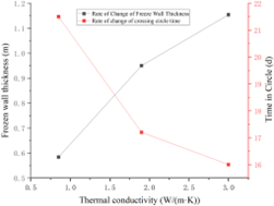
Thermal conductivity coefficient (λ): It has the most significant impact on the freezing effect [17]. As shown in Figure 2, when the thermal conductivity coefficient decreases from 1.9 W/(m·K) under the standard working condition to 0.85 W/(m·K), the effective thickness of the frozen wall decreases sharply from 0.95 m to 0.584 m, a decrease of 39%, and the closure time extends from 17.2 days to 21.5 days. This means that in strata with poor thermal conductivity, it is easier to form a weak frozen wall with insufficient thickness.
Figure 2. Influence of stratum thermal conductivity coefficient on freezing effect
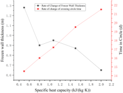
Figure 3. Influence of stratum specific heat capacity on freezing effect
Specific heat capacity (c): The specific heat capacity determines the heat required for the unit temperature change of the soil [18]. As shown in Figure 3, when the specific heat capacity increases from 0.5 kJ/(kg·K) to 2.0 kJ/(kg·K), the thickness of the frozen wall decreases from 1.28 m to 0.65 m, a decrease of 49.2%, and the closure time also extends from 14.5 days to 21.5 days.
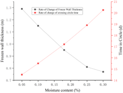
Figure 4. Influence of stratum moisture content on freezing effect
Moisture content (ω): The moisture content is directly related to the total amount of water to be frozen [19]. As shown in Figure 4, when the moisture content increases from 18% to 30%, the thickness of the frozen wall decreases from 0.95 m to 0.77 m, and the closure time extends from 17.2 days to 20.25 days. The higher the water content, the greater the cooling capacity required for freezing, the slower the freezing rate, and the higher the average temperature of the frozen soil, resulting in low strength of the frozen wall.
Through systematic sensitivity analysis, the influence of stratum thermal physical parameters on the freezing effect (taking the frozen wall thickness at 45 days as the evaluation index) is quantitatively studied.
3.2 Sensitivity influence of thermal physical parameters of stratum
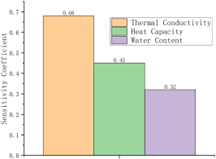
The sensitivity analysis of stratum thermal physical parameters is shown in Figure 5. The figure shows that among the three parameters of thermal conductivity coefficient, specific heat capacity and moisture content, the thermal conductivity coefficient has the most significant sensitivity to the frozen wall thickness. The sensitivity of the freezing effect to the thermal conductivity coefficient is as high as 0.68. This means that in strata with high mud content and fine particles, the thermal conductivity is poor, and the closure time and thickness of the frozen wall will be greatly affected. The sensitivities of the freezing effect to specific heat capacity and moisture content are 0.45 and 0.32, respectively. This indicates that during construction in water-rich strata, full consideration must be given to the problem of reduced freezing efficiency caused by high moisture content.
Figure 5. Sensitivity of freezing effect to stratum thermal parameters
3.3 Thermodynamic influence of freezing design and construction parameters
(1) Spacing of freezing pipes
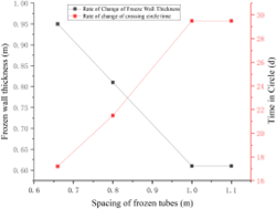
The spacing of freezing pipes is one of the most critical parameters in the design [20-23]. As shown in Figure 6, when the spacing increases from 0.66 m to 1.00 m, the closure time increases sharply from 17.2 days to 29.5 days, and the thickness of the frozen wall also decreases from 0.95 m to 0.61 m. The sensitivity of the frozen wall thickness to the pipe spacing is as high as 0.59. In actual construction, due to the deviation of drilling, the actual spacing at the bottom of the hole may be much larger than the design value, which is very easy to form an unclosed "window" between the pipes, becoming a water inrush channel. The positioning defect of the freezing pipe (such as the far end being 20 cm away from the auxiliary freezing surface) is the embodiment of this problem.
Figure 6. Influence of freezing pipe arrangement on freezing effect
(2) Freezing pipe diameter and convective heat transfer
In theory, increasing the diameter of the freezing pipe can increase the heat exchange area, which is beneficial to freezing [24]. However, the increase of pipe diameter will lead to changes in the velocity distribution of brine in the pipe, reducing the convective heat transfer coefficient between the brine and the pipe wall, thereby offsetting the positive effect of increasing the pipe diameter. Therefore, simply increasing the pipe diameter is not recommended to improve the freezing effect in sandy pebble strata.
(3) Improper setting of insulation layer
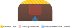
Laying an insulation layer inside the tunnel segment is to prevent the loss of cold energy into the tunnel. Simulation analysis shows that if there is no insulation layer, a large amount of cold energy will be lost in the intersection area of the connecting passage and the shield tunnel, resulting in seriously insufficient thickness of the frozen wall in this area, and the average temperature cannot reach the design requirement of below -10℃, forming structural defects. Behind the tunnel segment without the insulation layer, the isotherm retracts significantly, forming a weak freezing "gap", where water inrush is very easy to occur during excavation, as shown in Figure 7.
(4) Positioning defect at the far end of the freezing pipe
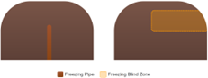
For the main freezing surface drilled from a single side tunnel, the design requires that the end (far end) of the freezing pipe must penetrate into the soil behind the segment of the other side tunnel for a certain distance [25, 26]. If the drilling depth is insufficient, resulting in the far end of the freezing pipe staying near the auxiliary tunnel, a "freezing blind zone" will be formed in the arch area of the auxiliary tunnel. The frozen soil in this area cannot develop effectively, and water inrush is very easy to occur during excavation, as shown in Figure 8.
Figure 7. Schematic diagram of freezing defects caused by missing insulation layer
Figure 8. Schematic diagram of positioning defect at the far end of freezing pipe
Taking the water inrush restoration project of the shield receiving section of Hunan Metro Line 3 as a typical case, this chapter deeply analyzes how to apply thermodynamic principles to practical engineering, and verifies the specific influences and coping strategies of the key factors mentioned in Chapter 3 in actual construction.
4.1 Engineering background and thermodynamic challenges
After the receiving of the left-line shield in this project, sudden water and sand inrush occurred, leading to large-scale collapse of the double-line tunnel, which is the first such serious accident in China. The restoration faces the following main thermodynamic challenges:
(1) High confined water and strong seepage: The groundwater has a close hydraulic connection with the Yangtze River and Qinhuai River, with a high confined water head of 6.6 m. Continuous seepage will cause strong thermal convection interference to the freezing process.
(2) Severe stratum disturbance: The accident and subsequent backfill grouting lead to loose soil and cavities, and its thermal physical properties (such as thermal conductivity coefficient and moisture content) become extremely uneven, bringing great difficulties to the prediction and control of the freezing temperature field.
(3) Complex thermal boundary conditions: Obstacles such as shield frame and plunger in the tunnel, as well as adjacent buildings to be protected, constitute complex multi-dimensional thermal boundary conditions.
4.2 Thermodynamic design of "separate hole arrangement and simultaneous freezing" scheme
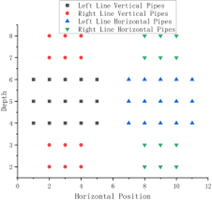
To avoid the problems of long construction period and excessive freezing body caused by "integrated freezing" in the restoration of Shanghai Metro Line 4, this project innovatively adopts the double-line separate hole arrangement and simultaneous freezing scheme, as shown in Figure 9. The figure shows the arrangement of independent vertical freezing pipe rings and horizontal freezing pipe rings for the left and right line tunnels, highlighting the concept of "separation" and comparing with the traditional integrated hole arrangement. The thermodynamic advantages of this design are:
More targeted: Tailor-made freezing schemes for each tunnel to avoid the waste of cold energy in the middle area caused by the large spacing between tunnels.
Controllable thermal interference: By independently controlling the brine circulation systems of the left and right lines, the problem of uneven freezing rate caused by geological differences can be better adjusted.
Figure 9. Schematic diagram of double-line separate freezing hole arrangement scheme
4.3 Thermodynamic response and problem diagnosis during construction
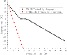
(1) Verification of temperature field development and influence of seepage
The measured data fully confirm the analysis in Chapter 3. As shown in Figure 10, the figure compares the temperature drop processes of T3 (greatly affected by seepage) and T7 (located inside the frozen soil curtain) temperature measuring holes. The phase change plateau stage of T3-8 measuring point is significantly longer, and the temperature is always higher. The temperature drop rate of T3-8 measuring point located in the high-pressure water-rich sand layer at the bottom of the tunnel is significantly slower than that of other measuring points. Although the surrounding freezing pipes (A1, A2) are deflected upward (maximum 117 mm), the calculation shows that the influence of heat exchange on the freezing effect of the measuring point is greater than that of the deflection of the freezing hole. The development rate of the frozen wall in this area is the slowest (26.6 mm/d), which is the top priority of freezing waterproofing.
Figure 10. Comparison of temperature change curves of temperature measuring holes at different positions
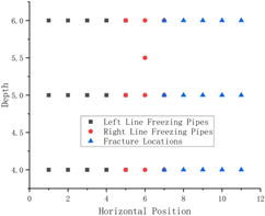
(2) Thermo-mechanical coupling mechanism of freezing pipe fracture
During the second phase of horizontal freezing, an abnormal phenomenon of 10 freezing pipe fractures occurred, as shown in Figure 11. This schematic diagram marks the specific positions of the fracture points on the freezing pipe layout diagram, and it can be seen that the fracture points are mostly concentrated in the area adjacent to the left and right lines where the frost heave force overlaps. This is not only a mechanical problem, but also the result of thermo-mechanical coupling:
Thermal factor (cause): Double-line simultaneous freezing, the frozen wall in the adjacent area of the left and right lines (small spacing) closes rapidly, forming a huge and continuous frozen soil mass.
Mechanical consequence (effect): The expansion of frozen soil (frost heave) generates a huge expansion force. In the disturbed and uneven stratum, this frost heave force cannot be released uniformly, generating a non-negligible lateral bending stress on the freezing pipe. When this stress exceeds the yield limit of the steel pipe, fracture occurs.
Data support: The fracture phenomenon began to appear on the 15th day of freezing and concentratedly broke out after the 24th day, which is highly consistent with the expected time point when the frozen wall closes and significant frost heave force is generated.
Figure 11. Schematic diagram of fracture positions of freezing pipes in the second phase
(3) Thermodynamic explanation for the extension of active freezing period
As shown in Table 1, the active freezing period of horizontal freezing in this project is as long as 45 days, which is much longer than the 35 days of conventional portal freezing. This is a direct result of the "stratum disturbance" and "uneven initial temperature field" mentioned in Chapter 3. The uneven soil structure and thermal physical properties lead to uneven cold energy distribution and large local heat load. To achieve the designed frozen wall thickness and average temperature (-13℃), the freezing time must be extended.
Table 1. Summary of freezing effects in the restoration project of Hunan metro line 3
|
Engineering Stage |
Tunnel Line |
Active Freezing Days (d) |
Minimum Frozen Wall Thickness (m) |
Average Temperature of Frozen Wall (℃) |
|
First-phase vertical freezing |
Left line |
32 |
3.2 |
-16.00 |
|
First-phase vertical freezing |
Right line |
35 |
3.1 |
-16.55 |
|
Second-phase horizontal freezing |
Left line |
45 |
2.7 |
-13.02 |
|
Second-phase horizontal freezing |
Right line |
45 |
3.2 |
-13.06 |
Based on the aforementioned theoretical and case analysis, this chapter systematically proposes a set of thermodynamic optimization measures for artificial ground freezing method in water inrush prevention, aiming to improve freezing efficiency and ensure construction safety.
5.1 Design optimization based on thermal physical exploration
(1) Refined exploration: Before freezing design, it is necessary to increase the number of exploration points, focusing on obtaining data such as moisture content, particle gradation, permeability coefficient and in-situ temperature in the construction area, which are used to accurately calculate the heat load and predict the freezing time.
(2) Parameter sensitivity design: Introduce sensitivity analysis in the design stage. Referring to the conclusions in Chapter 3, prioritize controlling factors with great influence on thermal conductivity coefficient (such as mud content), and formulate stronger freezing schemes (such as reducing hole spacing) for water-rich areas and seepage paths.
5.2 Construction control for thermo-mechanical coupling problems
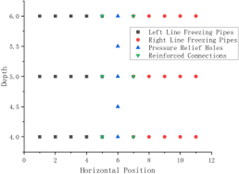
(1) Freezing pipe reinforcement and pressure relief technology:
Structural reinforcement: Aiming at the pipe breakage problem caused by frost heave force, it is recommended to adopt the joint reinforcement measure of "inner sleeve + welding" in the area of adjacent pipelines with complex stress, and select freezing pipes with a thickness increased to 10 mm.
Active pressure relief: Pre-drill special pressure relief holes in the area with concentrated frost heave force between the left and right lines. As shown in Figure 12, on the basis of separate hole arrangement, several rows of pressure relief holes are added between the left and right line tunnels, and the positions of joint reinforcement for adjacent freezing pipes are marked to intuitively show the optimization scheme. Provide a release channel for frost heave, fundamentally reducing the risk of pipe breakage.
(2) Differentiated freezing strategy:
For the identified high seepage areas, "intermittent freezing" (intermittent start-up freezing) can be implemented or the brine temperature can be appropriately increased to slow down the freezing rate, so that the frost heave force is released gently and stress concentration is avoided.
For areas with low initial temperature (such as grouting body), the flow rate of nearby freezing pipes can be appropriately adjusted to achieve balanced development of the temperature field.
Figure 12. Schematic diagram of optimized freezing pipe arrangement and pressure relief system
5.3 Whole-process dynamic thermodynamic monitoring and feedback
(1) Construct an intelligent temperature control system: Establish a real-time monitoring system centered on the total supply/return temperature of brine, the flow rate and temperature of each branch, and the data of key temperature measuring holes. The system realizes a closed-loop control process of "data collection (temperature measuring hole/flow meter) → data processing and comparison with prediction model → deviation analysis → decision-making (adjusting brine temperature/flow rate) → execution". The system should dynamically adjust the brine temperature and flow distribution according to the deviation between the measured temperature field and the design predicted value.
(2) Establish an early warning and intervention mechanism:
Early warning: When the temperature drop rate of key weak points (such as the bottom seepage area) is lower than the set threshold, the system alarms.
Intervention: Once an alarm is issued, the emergency plan can be activated immediately, such as adding auxiliary freezing pipes to the area, adjusting the operating parameters of nearby freezing pipes, etc., to achieve "precision freezing".
Through the above full-chain thermodynamic optimization from design, construction to monitoring, the reliability, safety and economy of the artificial ground freezing method in water inrush prevention of complex strata can be significantly improved.
(1) The artificial ground freezing method has a significant effect in water inrush prevention of metro tunnels, but its successful implementation depends on the systematic control of stratum thermal physical properties, freezing design parameters and construction technology. Thermodynamic analysis shows that the evolution of the temperature field during freezing presents obvious three-stage characteristics: rapid cooling stage, phase change plateau stage and slow cooling stage.
(2) The thermal physical parameters of the stratum have a significant impact on the freezing effect, among which the thermal conductivity coefficient has the most prominent influence (sensitivity 0.68). In water-rich sandy pebble strata, the thermal conductivity coefficient may change significantly due to differences in sand content, clay particle content, gradation, moisture content, etc., thereby affecting the closure time of the frozen wall and the distribution of freezing temperature.
(3) Freezing design and construction parameters have a decisive impact on the freezing effect. For every 14 cm increase in the spacing of freezing pipes, the closure time is prolonged by about 4.3 days; the positive effect brought by the increase of freezing pipe diameter will be offset by the decrease of brine convective heat transfer coefficient; the lack of insulation layer will lead to the formation of weak freezing areas in the intersection area of the tunnel and the connecting passage.
(4) The practice of the restoration project of Hunan Metro Line 3 shows that the double-line separate hole arrangement and simultaneous freezing scheme can effectively solve the problems of long construction period and excessive freezing body caused by traditional integrated freezing. At the same time, aiming at the problem of freezing pipe fracture, the proposed measures of pressure relief hole setting and pipeline reinforcement effectively solve the problem of pipeline damage caused by frost heave force.
(5) Groundwater seepage has a significant impact on the freezing process. The development rate of the frozen wall in the seepage area (26.6 mm/d) is only 78% of that in the normal area. Therefore, when implementing artificial ground freezing in high seepage strata, special attention should be paid to the monitoring and strengthening measures of the freezing effect in the seepage path area.
(6) Through the closed-loop control of data collection, model comparison, deviation analysis, decision-making and execution, the intelligent temperature control system can realize the precise control of the freezing process, providing technical guarantee for the safe application of the artificial ground freezing method under complex engineering conditions.
This work is supported by the Scientific Research Project of Chongqing Municipal Education Commission (Grant No.: KJZD-K202503801), and College-Level Scientific Research Project, Chongqing Water Resources and Electric Engineering College (Grant No.: K202314), and Chongqing Water Conservancy Science and Technology Project (Grant No.: CQSLK-2024014).
[1] Kabdyrakova, A.M., Kunduzbayeva, A.Y., Mendubayev, A.T., Batyrbekov, E.G., et al. (2025). Mechanisms of the formation of radioactive soil contamination in the waterstream zone from the tunnel in the area of underground nuclear tests at the Degelen site, Semipalatinsk test site. Science of the Total Environment, 1000: 180443. https://doi.org/10.1016/j.scitotenv.2025.180443
[2] Hu, J., Gan, H., Zhang, S., Ye, T., Liu, B., Wei, K. (2025). Temperature field study of forced thawing by pipe curtain freezing method in Sanya submarine tunnel. Marine Georesources & Geotechnology, 43(8): 1523-1539. https://doi.org/10.1080/1064119X.2024.2417763
[3] Go, G.H., Le, V.D. (2025). Optimization study on artificial ground freezing in elliptical tunnel construction: A comprehensive analysis of groundwater flow and thermodynamic parameters of soil. Tunnelling and Underground Space Technology, 163: 106774. https://doi.org/10.1016/J.TUST.2025.106774
[4] Pengtao, A.N., Shun, L. (2025). Analysis of the influence characteristics of hidden karst cavities on water gushing in tunnels under heavy rainfall conditions. Carbonates and Evaporites, 40(3): 85. https://doi.org/10.1007/S13146-025-01121-0
[5] Wang, J.G., Ma, Z., Cong, Y.R., Yang, S. (2025). Acoustic behavior and time prediction method for water inrush of tunnel floor under osmotic water pressure. Results in Engineering, 26: 105547. https://doi.org/10.1016/J.RINENG.2025.105547
[6] Hu, J., Gan, H., Zhou, J., Ye, T., Huang, L., Shang, X. (2025). Key issues in using the freezing method in power tunnel rehabilitation projects. Applied Sciences, 15(8): 4200. https://doi.org/10.3390/APP15084200
[7] Geisler, T., Kaml, G., Marcher, T. (2024). Sustainable energy from the depths: Optimization strategies for hydrothermal tunnel water systems. Geomechanik und Tunnelbau, 17(5): 426-436. https://doi.org/10.1002/GEOT.202400046
[8] Moser, H.R. (2024). Diffusion across a concentration step: Strongly nonmonotonic evolution into thermodynamic equilibrium. Physics Open, 21: 100239. https://doi.org/10.1016/J.PHYSO.2024.100239
[9] Halter, T., Gholizadeh Doonechaly, N., Notzon, A., Rybach, L., Hertrich, M., Giardini, D. (2024). Exploring the feasibility of energy extraction from the Bedretto Tunnel in Switzerland. Energies, 17(15): 3669. https://doi.org/10.3390/EN17153669
[10] Farhadian, H., Bahmani Shahraki, F. (2024). Enhancing analytical methods for estimating water inflow to tunnels in the presence of discontinuity areas. Environmental Earth Sciences, 83(10): 339. https://doi.org/10.1007/S12665-024-11651-W
[11] Nouali, M., Ghorbel, E. (2024). Hygro-thermo-mechanical properties of tunnel excavated earth-based plasters. Journal of Building Physics, 47(6): 651-671. https://doi.org/10.1177/17442591241238438
[12] Geisler, T., Richter, W., Marcher, T. (2024). Enhancing the performance of open geothermal tunnelwater systems by heat absorbers. Tunnelling and Underground Space Technology, 145: 105591. https://doi.org/10.1016/J.TUST.2024.105591
[13] Kulkarni, A., Yardimci, M., Kabir Sikder, M.N., Batarseh, F.A. (2023). P2O: AI-driven framework for managing and securing wastewater treatment plants. Journal of Environmental Engineering, 149(9): 04023045. https://doi.org/10.1061/JOEEDU.EEENG-7266
[14] Duan, Y., Rong, C., Long, W. (2023). Numerical simulation study on frost heave during the freezing phase of shallow-buried and undercut tunnel using the freeze-sealing pipe roof method. Applied Sciences, 13(18): 10344. https://doi.org/10.3390/APP131810344
[15] Khan, J., Ahmed, W., Waseem, M., Ali, W., et al. (2023). Lowari tunnel water quality evaluation: Implications for tunnel support, potable water supply, and irrigation in Northwestern Himalayas, Pakistan. Applied Sciences, 13(15): 8895. https://doi.org/10.3390/APP13158895
[16] Xiang, H., Zhang, G., Cheng, P., Hu, J., Wang, Z., Zeng, D. (2023). Analyses of the ground surface displacement under reinforcement construction in the shield tunnel end using the artificial ground freezing method. Applied Sciences, 13(14): 8508. https://doi.org/10.3390/APP13148508
[17] Mahmoodzadeh, A., Ghafourian, H., Mohammed, A.H., Rezaei, N., Ibrahim, H.H., Rashidi, S. (2023). Predicting tunnel water inflow using a machine learning-based solution to improve tunnel construction safety. Transportation Geotechnics, 40: 100978. https://doi.org/10.1016/J.TRGEO.2023.100978
[18] Healy, J., Atefi-Monfared, K. (2023). Fire-induced damage in tunnels: Thermo-mechanical modeling incorporating support system and geological conditions. Tunnelling and Underground Space Technology, 135: 105027. https://doi.org/10.1016/J.TUST.2023.105027
[19] Geisler, T., Wolf, M., Götzl, G., Burger, U., et al. (2023). Optimizing the geothermal potential of tunnel water by separating colder sectional discharges-Case study Brenner Base Tunnel. Renewable Energy, 203: 529-541. https://doi.org/10.1016/J.RENENE.2022.12.069
[20] Das, D., Bag, S., Pal, S., Sharma, A. (2022). Material defects in friction stir welding through thermomechanical simulation: dissimilar materials with tool wear consideration. Materials, 16(1): 301. https://doi.org/10.3390/MA16010301
[21] Dall’Alba, V., Neven, A., de Rooij, R., Filipponi, M., Renard, P. (2023). Probabilistic estimation of tunnel inflow from a karstic conduit network. Engineering Geology, 312: 106950. https://doi.org/10.1016/J.ENGGEO.2022.106950
[22] Vanarelli, M.J. (2023). Validation of a semi-empirical procedure for estimating steady-state, groundwater inflows in shallow rock tunnels through case study analyses. Transportation Infrastructure Geotechnology, 10(6): 1224-1238. https://doi.org/10.1007/S40515-022-00262-2
[23] Niu, Y., Hong, Z., Zhang, J., Han, L. (2022). Frozen curtain characteristics during excavation of submerged shallow tunnel using Freeze-Sealing Pipe-Roof method. Research in Cold and Arid Regions, 14(4): 267-273. https://doi.org/10.1016/J.RCAR.2022.08.003
[24] Burger, U., Geisler, T., Lehner, F., Cordes, T., Marcher, T. (2022). Sectional discharges as geothermal potentials of deep tunnels. Geomechanics and Tunnelling, 15(1): 92-103. https://doi.org/10.1002/GEOT.202100089
[25] Nakano, K., Kuremochi, N., Matsuda, M., Kunimura, S., Isago, N. (2021). Analysis of heaving phenomenon in mountain tunnel and consideration to shallow shaped invert as countermeasures. IOP Conference Series: Earth and Environmental Science, 833(1): 012079. https://doi.org/10.1088/1755-1315/833/1/012079
[26] Mahmoodzadeh, A., Mohammadi, M., Noori, K.M.G., Khishe, M., Ibrahim, H.H., Ali, H.F.H., Abdulhamid, S.N. (2021). Presenting the best prediction model of water inflow into drill and blast tunnels among several machine learning techniques. Automation in Construction, 127: 103719. https://doi.org/10.1016/J.AUTCON.2021.103719