Zaid Ali Hussein*![]() | Tareq Rahman Mahmood
| Tareq Rahman Mahmood![]() | Kayser Aziz Ameen
| Kayser Aziz Ameen![]()
© 2025 The authors. This article is published by IIETA and is licensed under the CC BY 4.0 license (http://creativecommons.org/licenses/by/4.0/).
OPEN ACCESS
This study presents a novel approach to improve the thermal performance of solar collectors by modulating the inlet velocity rather than altering the channel geometry. A comprehensive numerical analysis was carried out using ANSYS FLUENT with the realizable k–ε turbulence model to solve the governing equations of fluid flow and heat transfer. Three configurations were investigated: A flat channel with steady inlet velocity, a sinusoidal wavy-walled channel, and a flat channel subjected to sinusoidal velocity modulation. Key thermal and hydraulic parameters, including the Nusselt number, friction factor, and thermal performance factor (TPF), were evaluated over a wide range of Reynolds numbers. Results demonstrate that sinusoidal velocity modulation significantly enhances heat transfer, achieving up to a 45% increase in the average Nusselt number at high Reynolds numbers while maintaining minimal pressure penalties. By contrast, the wavy-walled channel provides only moderate enhancement accompanied by considerable friction losses. These findings establish dynamic velocity modulation as a cost-effective and scientifically robust alternative to geometric modifications, with strong potential for application in compact and energy-efficient heat exchangers and solar thermal systems.
CFD simulation, Nusselt number, sinusoidal velocity modulation, solar collectors, structured wall geometry, thermal performance factor, turbulent flow
Convective heat transfer over surfaces that are geometrically altered is important in many engineering applications such as cooling of electronic-components based, solar-based energy systems, chemical processing and plate-type condensers [1]. The use of waving channels results in an intentional breaking of the boundary layer and consequently leads to an improved convection heat transfer coefficient [2]. Numerous recent studies are addressing these geometries used to enhance thermal performance. Naphthalene sublimation was used to analyze localized and average heat transfer properties in a channel with triangul v- v-undulating surface as shown in the previous studies [3-5]. By comparing results of two periodic corrugation cycles at laminar, transitional and turbulent flow regimes, the presence of secondary flows was detected and an average heat transport rate up to three times higher than for smooth channels was obtained. Another investigation was focused on the effects of flow enhancement due to turbulence inside sinusoidal channels [6]; in this case, maximum Nusselt numbers were observed before wave crests and decreased behind them. Subsequent observations pointed out that the flow became completely developed at later waves, which means constant heat transfer rates. Wang and Chen [7] investigated the forced convection in sinusoidal channels using mathematical transformation and spline interpolation. Mereu et al. [8] conducted the CFD analysis in wavy rectangular channels with an incompressible flow model by the RANS turbulence model. Their work spanned a wide range of Reynolds numbers (1000-10000) and considered changes in wave properties and duct geometry - aspects not examined in detail by previous studies. Yin et al. [1] considered oscillatory wall motion and examined how the wave phase difference of upper and bottom walls affects both temperature and flow fields under, in particular, Pr = 0.696 and Re from 2000 to 10000. Haridas et al. [2] analyzed the effect of phase shift at Pr = 6.13 for Reynolds numbers between 350 and 1000, and reported that a few-slope angle of zero degrees produced the maximum heat transfer improvement. Shakir et al. [9] confirmed by experiments that the performance of heat transfer is enhanced with increasing flow rate in corrugated plate heat exchangers. This is primarily due to the increased flow that brings about more turbulence and better contact between surface and fluid. Another numerical work investigated fluid flow and heat transfer in a wavy microchannel through numerical simulation and flow visualization, showing that the reduction in wavelength enhances the heat transfer while increasing pressure loss penalties [10]. Other works have also studied the influence of curvature profile on heat transfer characteristics [11-14]. Other investigations addressed twisted or helically whapped channels studying the influence of wave amplitude and flow rates in heat and fluid transport [15-20]. Wavy geometries and nanofluid properties have also been combined to examine their possible combined impact on heat transfer phenomena. Previous studies mainly focused on the microstructural modification of the channel wall for performance enhancement. Despite considerable attention having been paid to the improvement of heat transfer by means of structural modification of channel walls, limited attention has been given to change in inlet velocity distribution. Most of the previous works have concentrated on the effects of geometrical modifications, such as wavy or corrugated or twisted channel walls getting an augmentation in convective heat transfer. Although these strategies may enhance turbulence and mixing, they usually result in increased manufacturing costs and elevation of the pumping power. Instead, the current work focuses on an alternative concept of velocity modulation as a possible new technique. Rather than modifying the physical geometry itself, a sinusoidally varying inlet velocity is applied and it offers the possibility of delivering thermal enhancement equal or superior to that obtained with less hydraulic loss. This innovation is the major contribution of the present work, which has been scarcely addressed in literature. In this work, we propose a novel approach by employing a periodically changing (i.e., sinusoidal) inlet flow velocity to exploit the thermohydraulic benefits of wavy walls. This adaptation in flow can be accomplished using parts such as automatic valves, variable speed pumps or other dynamic regulators. In this paper, we investigate the effect of using sinusoidal profiled inlet velocity on solar thermal channel performance for both hydraulic and thermally based cases, serving as a substitute of modifying channel wall shape. The computations are performed by the use of computational fluid dynamic (CFD) methods. To do so, three different flow scenarios were modelled and compared with ANSYS FLUENT: a straight, planar channel with uniform inlet velocity distribution, a sinusoidal-channel (varicose) configuration and a flat channel under the influence of pulse-like-inlet velocities. Performance parameters such as Nusselt number, friction factor, and thermal performance factor have been considered to assess both the thermal improvement and hydraulic effect.
The realizable k–ε model is used in this study to numerically simulate the fundamental equations that govern fluid flow and heat transfer with ANSYS FLUENT® software under all cases, where water is considered as the working medium. Both laminar and turbulent flow regimes are taken into account in the simulations. In order to assess the system performance and its pumping power, metrics including Nusselt number, friction factor and thermal performance factor (TPF) are fully analysed. It was investigated three geometrical conditions to evaluate the effects of different structure contour and duct geometry on thermal behaviour.
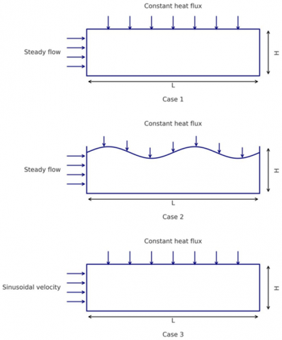
For all configurations, the geometry used is inserted once for all the cases and is made by a channel of 35 cm in length and a height of 20 cm, which enables comparison to be established. In second configuration, the undulated surface profile was generated by employing sinusoidal mathematical expression (Eq. (1)) [1]:
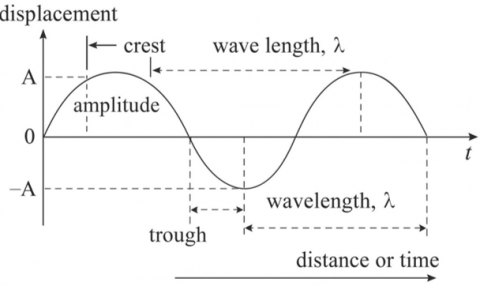
$y=A \cdot \sin \left(\frac{2 \pi}{\lambda} \cdot x\right)$ (1)
where, $A$ refers to the height of the wave crest (amplitude), $\lambda$ (lambda) signifies the spatial period of the wave, that is, the wavelength, and $x$ refers to the longitudinal coordinate along the channel.
Figure 1 illustrates the geometrical configuration, and Figure 2 presents a portion of the sine-shaped wave pattern.
Figure 1. Illustration of the three channel configurations (Cases 1–3) with dimensions L = 0.35 m and H = 0.20 m
Figure 2. Sinusoidal wall profile with geometrically defined amplitude (A) and wavelength (λ)
The entering flow velocity in Case 3 also follows a sinusoidal variation with time, given by Eq. (2):
$\dot{x}=x \cdot \sin w t$ (2)
The continuity, momentum and energy equations apply to all three modelling cases [21, 22]. Furthermore, the k–ε turbulence model equations are included in the modelling to include turbulent flow effects. The realizable k–ε turbulence model was chosen because of its proven ability to predict internal turbulent flows with recirculation and boundary layer separation that are important for sinusoidal and velocity-modulated channels. The realizable model amounts to a correction of the standard k–ε, using an alternative expression for turbulent viscosity and a transport equation for dissipation. Though the k–ω SST model can provide better near-wall resolution, it requires much sharper grids (low y+ value) and higher computational costs. Because the main goal of this study is to assess global trends with respect to thermal-hydraulic performance across a wide range of Reynolds numbers rather than resolve finely detailed near-wall physics, use of the realizable k–ε model represents an appropriate compromise between computational cost and accuracy. Moreover, its successful use in similar channel-flow investigations indicates that it is appropriate for this treatment [8, 23-27]. For incompressible fluids, the continuity equation (for conservation of mass) is employed as in the research of Yin et al. [1]. These equations were numerically solved by the finite volume approach incorporated in ANSYS FLUENT.
Continuity equation:
$\rho\left(\frac{\partial u_x}{\partial x}+\frac{\partial u_y}{\partial y}+\frac{\partial u_z}{\partial z}\right)=0$ (3)
The momentum conservation is:
$\begin{gathered}\rho\left(\frac{\partial u}{\partial t}+u \frac{\partial u}{\partial x}+v \frac{\partial u}{\partial y}+w \frac{\partial u}{\partial z}\right) =-\frac{\partial p}{\partial x}+\rho g_x+\mu\left(\frac{\partial^2 u}{\partial x^2}+\frac{\partial^2 u}{\partial y^2}+\frac{\partial^2 u}{\partial z^2}\right)\end{gathered}$ (4)
X-component:
$\begin{gathered}\rho\left(\frac{\partial v}{\partial t}+u \frac{\partial v}{\partial x}+v \frac{\partial v}{\partial y}+w \frac{\partial v}{\partial z}\right) =-\frac{\partial p}{\partial y}+\rho g_y+\mu\left(\frac{\partial^2 v}{\partial x^2}+\frac{\partial^2 v}{\partial y^2}+\frac{\partial^2 v}{\partial z^2}\right)\end{gathered}$ (5)
Y-component:
$\begin{gathered}\rho\left(\frac{\partial w}{\partial t}+u \frac{\partial w}{\partial x}+v \frac{\partial w}{\partial y}+w \frac{\partial w}{\partial z}\right) =-\frac{\partial p}{\partial z}+\rho g_z+\mu\left(\frac{\partial^2 w}{\partial x^2}+\frac{\partial^2 w}{\partial y^2}+\frac{\partial^2 w}{\partial z^2}\right)\end{gathered}$ (6)
Z-component:
$\begin{aligned} & \{\text { Rate of change of enegy inside the fluid element }\} \\ & =\{\text { Net flux of heat into the element }\} \\ & +\left\{\begin{array}{c}\text { Rate of working done on the element } \\ \text { due to body and surface forces }\end{array}\right\} \\ & \rho c_p \frac{D T}{D t}=K \nabla^2 T+\mu \varnothing\end{aligned}$ (7)
The energy conservation is [19]:
$\begin{gathered}\emptyset=2\left[\left(\frac{\partial u}{\partial x}\right)^2+\left(\frac{\partial v}{\partial y}\right)^2+\left(\frac{\partial w}{\partial z}\right)^2\right] \\ +\left[\left(\frac{\partial u}{\partial y}+\frac{\partial v}{\partial x}\right)^2+\left(\frac{\partial v}{\partial z}+\frac{\partial w}{\partial y}\right)^2+\left(\frac{\partial w}{\partial x}+\frac{\partial u}{\partial z}\right)^2\right] \\ -\frac{2}{3}\left(\frac{\partial u}{\partial x}+\frac{\partial v}{\partial y}+\frac{\partial w}{\partial z}\right)^2\end{gathered}$ (8)
The thermophysical properties of the working fluid density $(\rho)$, viscosity ($\mu$), specific heat capacity ($c_p$) and thermal conductivity ($k$) are denoted by their traditional symbols. The velocity components in Cartesian coordinate system $(x, y, z)$ are $u, v, w$. In order to permit a good comparison between the various simulation scenarios, the following relations were employed to compute Nusselt number [26-32]:
$N u=\frac{h . L}{K}$ (9)
$h=\frac{q^{\prime \prime}}{\left(T_w-T_m\right)}$ (10)
$N u=\frac{q^{\prime \prime} . L}{K .\left(T_w-T_m\right)}$ (11)
The local temperature at the wall is denoted by $T_w$ in this case, and the mean fluid temperature, or $T_m$, can be obtained as follows [33-36]:
$T_m=\frac{\int_0^H u \cdot T d h}{\int_0^H u d h}$ (12)
Additionally, the Reynolds number (Re) is defined by the relation:
$R e=\frac{\rho u D_h}{\mu}$ (13)
Here, $D_h$ represents the hydraulic diameter, which is determined by the formula $\frac{4 A}{P}$.
All cases were simulated using the $k-\epsilon$ turbulent model, as they are suitable for internal flow [23].
For Kinetic energy in turbulent flow used (k) [1].
$\begin{gathered}\frac{\partial}{\partial t}(\rho k)+\frac{\partial}{\partial x_i}\left(\rho k u_i\right)=\left[\left(\mu+\frac{\mu_t}{\sigma_k}\right) \frac{\partial k}{\partial x_j}\right]+P_k+P_b- \rho \epsilon-Y_M+S_k\end{gathered}$ (14)
For the dissipation ϵ:
$\begin{gathered}\frac{\partial}{\partial t}(\rho \epsilon)+\frac{\partial}{\partial x_i}\left(\rho \epsilon u_i\right)=\frac{\partial}{\partial x_j}\left[\left(\mu+\frac{\mu_t}{\sigma_\epsilon}\right) \frac{\partial \epsilon}{\partial x_j}\right]+ C_{1 \epsilon} \frac{\epsilon}{k}\left(P_k+C_{3 \epsilon} P_b\right)-C_{2 \epsilon} \rho \frac{\epsilon^2}{k}+S_\epsilon\end{gathered}$ (15)
where, turbulent viscosity, $\mu_t$, is:
$\mu_t=\rho C_\mu \frac{k^2}{\epsilon}$ (16)
Production of k is:
$P_k=-\rho \overline{u_i^{\prime} u_j^{\prime}} \frac{\partial u_j}{\partial x_i}$ (17)
$P_k=\mu_t S^2$ (18)
In this context, $S$ denotes the magnitude of the mean strainrate tensor, which can be expressed mathematically as:
$S \equiv \sqrt{2 S_{i j} S_{i j}}$ (19)
The buoyancy effect is:
$P_b=\beta g_i \frac{\mu_t}{P r_t} \frac{\partial T}{\partial x_i}$ (20)
The term $g_i$ denotes the gravitational acceleration in the $i$-direction, while $P_{r t}$ refers to the turbulent Prandtl number related to energy transport. Its default value is commonly taken as 0.85 [22].
The description of the thermal expansion factor is:
$\beta=-\frac{1}{\rho}\left(\frac{\partial \rho}{\partial T}\right)_p$ (21)
The constant of the model:
$C_\mu=0.09, C_{1 \epsilon}=1.44, C_{2 \epsilon}=1.92, \sigma_\epsilon=1.3, \sigma_k=1$ (22)
Note: $C_{3 \epsilon}$ depends on the literature being followed and is meant to be used only with the $P_b$ term.
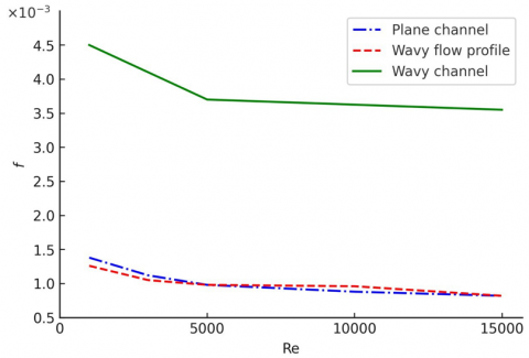
Due to the increased friction generated by the flow restriction, the increase in pumping power requirements is frequently associated with improved heat transfer performance. As a result, the friction factor, $f$, was considered in the research and compared to the scenarios of a plane and a wavy channel. In addition, the factor of performance (TPF), which indicates the transfer of heat ratio improvement to friction, was computed. Eqs. (16) and (17) were used to compute the friction factor and TPF, respectively [24,25].
$f=\frac{2 D_p}{\rho u^2} \frac{d p}{d x}$ (23)
$\eta=\frac{\left(N u / N u_p\right)}{\left(f / f_p\right)}$ (24)
where, the subscript $p$ refers to the plane channel.
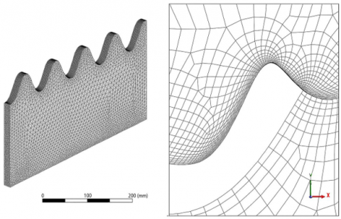
Computational analysis was carried out utilizing ANSYS FLUENT software, where the finite volume method (FVM) was applied to study fluid flow and thermal behavior across three distinct duct configurations: A flat duct with uniform flow, a duct featuring a sinusoidal wall profile, and a flat duct subjected to a sinusoidal velocity distribution. The computational domains were constructed using ANSYS Design Modeler. The wavy duct is fabricated based on the sinusoidal equation described previously in Section 2 that has an effective length of 350 mm and a height of 200 mm. The five full wave cycles were included on the upper surface of the model. Mesh generation was completed with ANSYS Meshing using a non-uniform triangular mesh to reflect the convoluted curvatures of the wavy surface. In order to better capture the steep gradients near boundaries, locally refined meshes were created close to the boundaries utilizing layered inflation schemes. Quality indices of mesh, such as skewness and orthogonality, were carefully controlled to guarantee numerical accuracy and stability. Figure 3 displays the mesh that is generated, giving a view of the full geometry and an expanded image near the curved wall. In this vicinity a finer mesh was used near the sinusoidal surface to capture the separation regions and thermal boundary layer behaviour accurately. In the simulation, the flow was assumed to be steady, incompressible and turbulent. Realizable k-ε model: The realizable model was retained because of its ability to resolve recirculatory zones and complex flow structures. Dirichlet type boundary conditions were applied with a specified wall heat flux and uniform velocity profile at the inlet. Second order upwind discretization schemes were employed and the pressure-velocity coupling was achieved by means of SIMPLE algorithm. Simulations were performed for a Reynolds number range between 1000 and 15000. Consistency in norm convergence was monitored and the thermal performance (Nusselt number) and flow resistance (friction factor) were of importance.
A two-dimensional flow field was simulated in this study using the FLUENT software. The physical region is shown in Figure 1. A steady simulation was performed with an inlet uniform velocity boundary condition and a uniform thermal wall flux. The number of the degree of freedoms ux, uy and pressure, were output according to the meshes, while dimensions for inflow/outflow conditions would be those corresponding to Reynolds Number equal to 1000. We also treated a distinct case with Credit value of 5000. It was, furthermore, assumed that atmospheric pressure equaled the outside pressure. The mesh distributions corresponding to these cases are shown in Figure 3. In general, the numerical approach allowed for the proper resolution of flow dynamics and thermal phenomena over a range of Reynolds numbers which made it possible valid comparison among all three investigated cases.
Figure 3. Computational mesh of the wavy channel showing overall grid distribution and refined cells near the sinusoidal
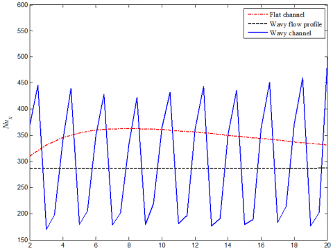
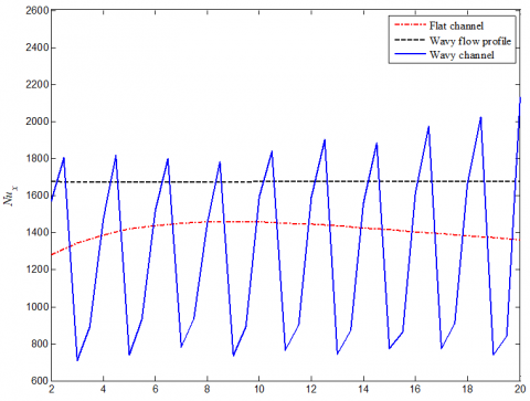
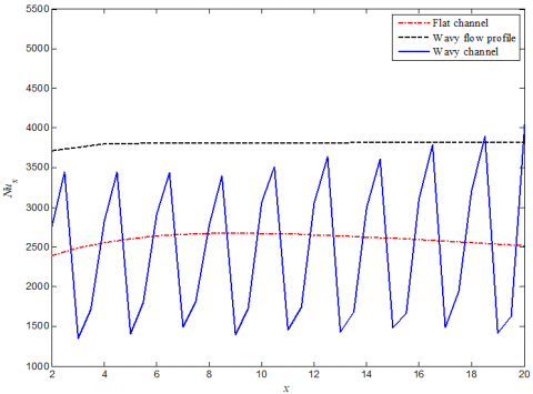
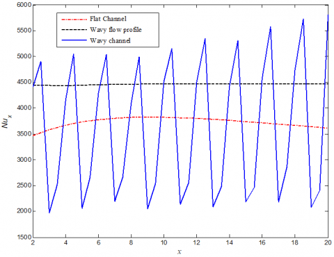
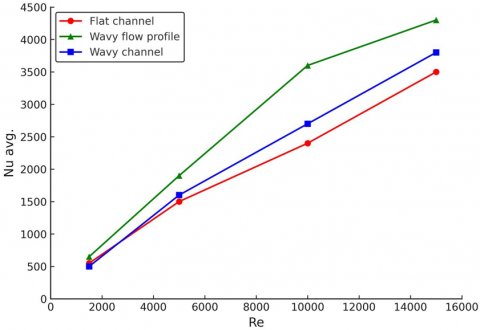
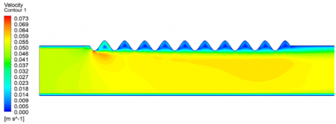
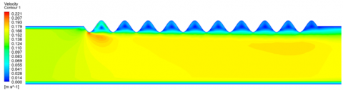
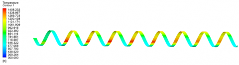
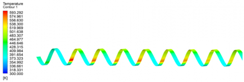
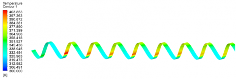
The current section is an in-depth analysis of the thermal and hydraulic characteristics under three different geometries, i.e., a flat channel with uniform flow, a wavy-walled channel, and a flat channel with sinusoidal velocity disturbances. The study is performed at several levels of Reynolds numbers, ranging from 1000 to 15000, for laminar as well as fully developed turbulent flow. Evaluation is performed by investigating the spatial and average Nusselt number distributions of velocity and temperature contours, friction factor, as well as thermal performance factor. In Figures 4-7, the local Nusselt number (Nux) as a function of the flow direction is plotted for the three configurations and at specific Re values arranged in ascending order including 1000, 5000, 10000 and 15000. The highest Nusselt number is obtained for the flat duct at Re = 1000 (laminar flow), and the lowest one for the case with a sinusoidal inlet velocity. This is attributed to the presence of a thermally resistive boundary layer near the channel walls at low Reynolds number flow. Wall waviness or oscillatory inlet velocity deepens this insulating layer under laminar flow and makes the convective heat transfer worse. The boundary layer along the wavy walls or subject to pulsatile flow thickens and less rate of velocity and hence thermal energy transfer take place at the Wall. There is a change in trend for the relative performance of configurations at Re = 5000, which corresponds to transitional flow. For flat channel, the current configuration is found to be inefficient in heat transfer and sinusoidal profile based one shows better results among alternatives. The breakdown of turbulence increases the mixing of the flow and thins the boundary layer. The wavy-walled cavity also facilitates the secondary flows and vortices that lead to augmented local Nusselt numbers, albeit less efficiently than the dynamic velocity shaping within their featured-profile. Figures 6 and 7 with Re = 10,000 and Re = 15,000, respectively are to support wavy velocity profile predominance in turbulent regimes. The greater Reynolds number results in a reduced and disturbed boundary layer which produces better heat transfer through convection. The sinusoidal velocity gives higher Nusselt numbers at all points along the channel, while there is a slight enhancement from flat channel for wavy-walled channel. As the sinusoidal velocity modulation is purely temporal without accompanying geometric roughness, the pressure penalty is low even as mixing becomes stronger. These results show the potential of active inlet designs to enhance convective heat transfer with less augmentation in frictional losses. Results clearly show that the thermal performance of the sinusoidal velocity forcing is superior to shaping the channel wall in changing the thermo-hydraulic characteristics. The mean value of the Nusselt number (Nu_avg) as a function of Reynolds number was compared in Figure 8. They all have an increasing behaviour with the increase of Reynolds numbers because of the more strengthened turbulence and convection process. But the rate of creeping flow to inertial flow turns out maximum for the waviness of the flow profile. At Re = 5000, the Nusselt-enhancement factor for the wavy profile yields approximately 21% with respect to the flat channel, and 1.5% in case of the wavy wall. At Re = 10000 it is approximately 4.5% for the wavy profile and 5.3% for the wavy wall. With Re = 15000, the improvements are 22% and 7.8%, respectively. This comparison clearly evidences that those systems injecting sinusoidal flow fluctuations are much effective than the ones with imposed geometry variations to encourage heat transfer under turbulence. More insights into the internal flow can be obtained from Figures 9 and 10. Figure 9 shows the distribution of the velocity field in the wavy-walled channel. Visible stagnation zones arise in low-Re conditions close to the wave troughs, where the fluid is heavily damped. These stagnation basins block heat interaction with the local environment, leading to temperature buildup. The stagnation zones are less detected with the increase of Reynolds number in such a way that there is higher turbulence intensity in which leads to the uniform velocity distribution and better thermal performance. The corresponding temperature distribution (Figure 10) reveals that local hotspots emerge in low-velocity bands.
Figure 4. Nusselt number for Re = 1000
Figure 5. Nusselt number for Re = 5000
Figure 6. Nusselt number for Re = 10000
Figure 7. Nusselt number for Re = 15000
Figure 8. The relationship between the average Nusselt number and Reynolds number
Re = 1000
Re = 5000
Re = 10000
Re = 15000
Figure 9. Velocity contour of the wavy channel
Re = 1000
Re = 5000
Re = 10000
Re = 15000
Figure 10. Temperature distribution on the wavy wall
Figure 11. The relationship between the friction factor and the Reynolds number
The thermal response becomes more homogeneous for chaotic flows, which suggests a better convective removal of the heat, as a result of stronger mixing and weaker thermal boundary layers. To quantify the hydraulic performance, f (friction factor) versus Re curves are shown in Figure 11. The friction values are least in the flat channel as expected. The correlated rough-wall channel has an additional turbulent pumping, frictional component due to flow blockage and roughness which increases the driving power. In contrast, the sinusoidal velocity profile involves only a marginal increase of friction over that for the flat channel, so that heat transfer is promoted without imposing a significant hydraulic cost.
Figure 12. The relationship between Reynolds number and thermal performance
Figure 12 exhibits TPF, capturing the balance between enhanced heat transfer and increase of pressure drop. The wavy velocity profile always obtains the appreciably highest TPF for all Reynolds numbers, which validates its capabilities in enhancing heat transfer at a low friction penalty. The wavy-walled channel has moderate heat transfer enhancement with higher Nusselt number and friction factor than the wavy profile, which leads to a TPF lower than that of the wavy profile. The flat duct is still the reference case having the lowest TPF, being characterized by a very small heat transfer enhancement factor. Such an excellent performance of the velocity-modulated channel is attributed to its capability of cyclically disturbing the developing boundary layer, resulting in improvement of fluid mixing and diminishing the average thermal boundary layer thickness. This system results in convective heat transfer rates that are well in excess of steady-flow conditions, especially at large Reynolds numbers for which oscillatory forcing enhances production of turbulence. By contrast, secondary vortices are produced by geometric curvature in wavy-walled channel; but the frictional penalties associated with them cancel out much of the thermal benefit yielding a lower total efficiency. Such mechanistic trends are consistent with those found in the literature. For example, Mereu et al. [8] pointed out that the serrated channels give only moderate Nusselt number enhancement at the cost of higher pressure drop, while Nauman et al. [27] found that the value of Nu_avg given by corrugated tubes increases gradually with Re. For comparison, the current VMC design reaches a maximum Nu_avg augmentation by up to 45% at Re = 10,000 over both conventional wavy configurations [8] and more recent corrugation designs [27]. This validates that dynamic modulation of flow is not only a more efficient approach toward enhancing convective transport, but it also provides better thermal performance at an economy of hydraulic cost. From an engineering point of view, 45% increase in heat transfer with essentially no pressure drop penalty in velocity modulation would be desirable for real systems. Unlike wavy-walled geometries that impose complex fabrication and higher pumping power, the approach presented here is applicable in flat channels with any structural changes. This is an inexpensive solution, which may be applicable in upgrading existing thermoelectric devices and, for example, compact solar collectors, electronic cooling modules, and advanced heat exchangers where there are demands on space and efficiency. Overall, the results show that a wavy flow condition used in a flat channel can be highly effective to improve thermal behaviour. It provides significant heat transfer enhancement particularly in the turbulent flow regime, and with a low pressure drop penalty. In contrast to geometrical changes like wavy walls, the dynamic flow concept introduces a more thermally and hydraulically effective behaviour of the heat exchanger or solar system, which means it can be considered as an attractive idea for improving advanced heat exchangers and solar systems performance.
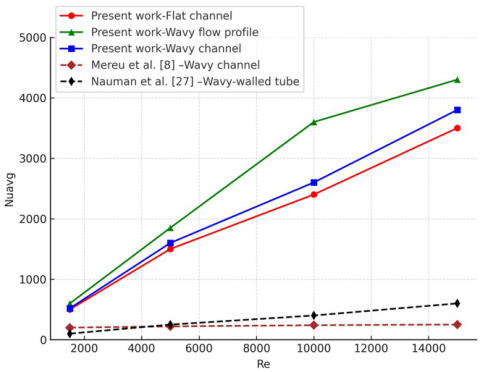
Figure 13 compares the Nu_avg versus Re trend obtained using CFD to that found by Mereu et al. [8]. The simulation has three cases: a flat channel, the sinuous wavy-wall for the channel and again with flat walls for the duct, but with periodic temporal fluctuations in a wavy inlet velocity that is (directly from case 2) referred to as 'wavy' velocity profile. The results can be seen that the dynamic velocity modulation has better thermal performance compared to two other geometries and even under high Reynolds number, Re > 5000. In particular, for this profile the increase of Nu_avg is much higher than that obtained in both flat and wavy-walled channels.
Figure 13. Comparison between current simulation and previous studies [8, 27] showing the variation of Nu_avg with Re
Despite possessing slight, desirable heat transfer features, the sinusoidal wavy-walled geometry presents a significant improvement in heat transfer based on dynamic and time-varying velocities distribution pattern indicating its potential predominant over straight channel. In addition to performance comparison, this validation also confirms in part the current numerical approach, where simulated trends are well matched with published works. which is supported by our results that the number patterns provided in this work are compared with those of Mereu et al. [8], and similar trends can be derived, indicating the credibility of the model in this case. It is worth mentioning, however, that the curve of Mereu et al. [8]; this behavior may resemble flatness in the figure because of scaling and graphical simplification, but it becomes more gradual when plotted as a function of Reynolds number for their own data. For example, the dynamic profile yields (at Re = 10000) up to a 45% increase of Nu_avg: this is by far its best performance in such conditions, with no associated pressure drop penalty. These results confirm the superiority of time-dependent flow modulation over structural effects in enhancing convective heat transfer in engineering applications. Figure 13 also includes the data of Nauman et al. [27] for wavy-walled tubes. They found that the corrugated geometry can give a moderate augmentation in the average Nusselt number as compared to smooth channels, but it is still far from what could be reached by the current velocity-modulated configuration. The Nauman results show only a relatively shallow increase of Nu_avg with Re in concordance with the low impact of geometrical corrugation in maintaining strong convective stirring. In contrast, the velocity-modulated channel in this work uniformly yields the highest Nu_avg over the range of Reynolds numbers tested with a maximum 45% augmentation occurring at Re = 10,000. This comparison emphasizes that velocity modulation is not just superior to the classical flat and sinusoidal wavy geometries but also to more advanced corrugated shapes. From an engineering standpoint, this would have significance: Geometric waviness provides some thermal enhancement with an additional fabrication complexity and higher frictional penalty when compared to a velocity modulation that has superior thermal response for a minor hydraulic penalty and without requiring any structural changes.
A numerical investigation was performed to assess the thermal and hydraulic performance of different types of channels (i.e., flat, wavy-walled and sinusoidal modulated inlet velocity). It was brought out that with respect to heat transfer effectiveness and flow behavior, Reynolds number as well as internal flow regime play a significant role. For laminar flow (Re ≤ 1000), an improved thermal performance was presented for the flat channel because of the continuous development of the thermal boundary layer. In comparison, the average Nusselt numbers of both curved wall and sinusoidal inlet velocity models decreased at around 13.5% and 24%, respectively. This decrease is related to the formation of a well-developed, thermally-insulating region near the walls, which suppressed convective heat transfer without mixing. An opposite trend has been noticed as the flow entered the turbulent region (Re ≥ 5000). Sinusoidal velocity profile outperformed the remaining ones regarding convective heat exchanger and enhanced average Nusselt number up to 45% higher at Re = 10000 as compared to the flat channel, while showing a better performance than that of wavy-walled configuration with an approximate value of 25.3%. Importantly, this enhancement was obtained without an increase in the pressure drop (the sinusoidal modulation promoted more flow unsteadiness and boundary layer disturbances rather than providing extra geometrical resistance to the flow). In contrast, although the wavy-walled channel provided a slight thermal enhancement, this was accompanied by significant hydraulic hindrance—increasing pressure loss up to 28.3% compared to baseline case—mediated by enhanced surface friction and partial flow obstruction. These results highlight that geometric changes do not necessarily yield optimal thermal systems when hydraulic costs are taken into account. Moreover, the results presented in this study are consistent with the computational findings reported by Mereu et al. [8] indicating the applicability of the current simulation method. The observed reproducibility suggests that the use of sinusoidal inlet velocity modulation is a viable and practical option to structural modifications. The hybrid offers a thermally well-balanced increase in performance combined with maintaining hydraulic efficiency and is, therefore, especially applicable to compact energy-restricted heat exchangers. A number of recent investigations have considered enhanced heat transfer in wavy and modulated channels, which also justifies the significance of the present study [28-36].
The following directions and recommendations in future studies can further extend the present work:
Recommending velocity modulation as a low-cost and easily implemented strategy for retrofitting existing flat channels, with strong potential in applications such as solar-thermal systems, electronic cooling, and advanced compact heat exchangers.
|
A |
the amplitude |
|
Dh |
hydraulic diameter |
|
gx, gy, gz |
gravitational acceleration in the x, y, and z directions |
|
H |
height of channel |
|
k |
energy associated with turbulence |
|
L |
length of channel |
|
Nu |
Nusselt number |
|
$P r_t$ |
turbulent Prandtl number |
|
Re |
reynolds number |
|
S |
magnitude of the mean strain rate tensor |
|
$T_m$ |
mean temperature |
|
TPF |
thermal performance factor |
|
$T_w$ |
local wall temperature |
|
ux, uy, uz |
velocity components along the x, y, and z axes |
|
Greek symbols |
|
|
$\lambda$ |
the wavelength |
|
$\rho$ |
density |
|
$\epsilon$ |
rate at which turbulent energy is dissipated |
|
$\mu_t$ |
turbulent viscosity |
[1] Yin, J., Yang, G., Li, Y. (2012). The effects of wavy plate phase shift on flow and heat transfer characteristics in corrugated channel. Energy Procedia, 14: 1566-1573. https://doi.org/10.1016/j.egypro.2011.12.1134
[2] Haridas, D., Singh, V., Srivastava, A. (2020). An experimental investigation of heat transfer performance of wavy channels under laminar flow conditions: An interferometric study. Journal of Enhanced Heat Transfer, 27(6): 561-576. https://doi.org/10.1615/JEnhHeatTransf.2020034450
[3] Abdel-Aziz, M.M., Khelifa, A., Attia, M.E.H., Bady, M. (2025). A numerical investigation on improving the thermal efficiency of PV panels through integration with solar water collectors. Solar Energy, 287: 113259. https://doi.org/10.1016/j.solener.2025.113259
[4] Jaber, M.W.K., Abdul Ghafoor, Q.J., Mohammed, A.A., Mahmoud, M.S., Khudheyer, A.F. (2022). Optimizing the size for solar parabolic trough concentrator numerically. International Journal of Mechanical Engineering, 7(1): 610-615.
[5] Mohammed, A.A., Mahmoud, M.S., Jebir, S.K., Khudheyer, A.F. (2024). Numerical investigation of thermal performance for turbulent water flow through dimpled pipe. CFD Letters, 16(12): 97-112. https://doi.org/10.37934/cfdl.16.12.97112
[6] Rasangika, A.H.D.K., Nasif, M.S., Pao, W., Al-Waked, R. (2022). Numerical investigation of the effect of square and sinusoidal waves vibration parameters on heat sink forced convective heat transfer enhancement. Applied Sciences, 12(10): 4911. https://doi.org/10.3390/app12104911
[7] Wang, C.C., Chen, C.K. (2002). Forced convection in a wavy-wall channel. International Journal of Heat and Mass Transfer, 45(12): 2587-2595. https://doi.org/10.1016/S0017-9310(01)00335-0
[8] Mereu, R., Colombo, E., Inzoli, F. (2013). Numerical analysis of fluid dynamics and thermal characteristics inside a wavy channel. International Journal of Numerical Methods for Heat & Fluid Flow, 23(6): 1049-1062. https://doi.org/10.1108/HFF-04-2011-0101
[9] Shakir, A.K., Mohammed, A.A., Mahmoud, M.S., Abbas, M.F. (2025). Numerical investigation for Y-shaped twisted inserts with trapezoidal perforations in heat exchangers. Heat Transfer. https://doi.org/10.1002/htj.70054
[10] Umavathi, J., Kumar, J.P., Shekar, M. (2010). Mixed convective flow of immiscible viscous fluids confined between a long vertical wavy wall and a parallel flat wall. International Journal of Engineering, Science and Technology, 2(6): 256-277. https://doi.org/10.4314/ijest.v2i6.63729
[11] Akbarzadeh, M., Rashidi, S., Esfahani, J. (2017). Influences of corrugation profiles on entropy generation, heat transfer, pressure drop, and performance in a wavy channel. Applied Thermal Engineering, 116: 278-291. https://doi.org/10.1016/j.applthermaleng.2017.01.076
[12] Ajeel, R.K., Salim, W.I., Hasnan, K. (2018). Thermal and hydraulic characteristics of turbulent nanofluids flow in trapezoidal-corrugated channel: Symmetry and zigzag shaped. Case Studies in Thermal Engineering, 12: 620-635. https://doi.org/10.1016/j.csite.2018.08.002
[13] Salami, M., Khoshvaght-Aliabadi, M., Feizabadi, A. (2019). Investigation of corrugated channel performance with different wave shapes: Nanofluid as working media. Journal of Thermal Analysis and Calorimetry, 138: 3159-3174. https://doi.org/10.1007/s10973-019-08361-y
[14] Khoshvaght-Aliabadi, M., Rad, S.H., Hormozi, F. (2016). Al2O3–water nanofluid inside wavy mini-channel with different cross-sections. Journal of the Taiwan Institute of Chemical Engineers, 58: 8-18. https://doi.org/10.1016/j.jtice.2015.05.029
[15] Khoshvaght-Aliabadi, M., Feizabadi, A. (2020). Compound heat transfer enhancement of helical channel with corrugated wall structure. International Journal of Heat and Mass Transfer, 146: 118858. https://doi.org/10.1016/j.ijheatmasstransfer.2019.118858
[16] Sadripour, S. (2018). Investigation of flow characteristics and heat transfer enhancement in a nanofluid flow in a corrugated duct. Journal of Applied Mechanics and Technical Physics, 59: 1049-1057. https://doi.org/10.1134/S002189441806010X
[17] Duan, Z., Muzychka, Y. (2010). Effects of axial corrugated roughness on low Reynolds number slip flow and continuum flow in microtubes. ASME Journal of Heat and Mass Transfer, 132(4): 041001 https://doi.org/10.1115/1.3211854
[18] Zhang, L., Che, D. (2011). Influence of corrugation profile on the thermalhydraulic performance of cross-corrugated plates. Numerical Heat Transfer, Part A: Applications, 59(4): 267-296. https://doi.org/10.1080/10407782.2011.540963
[19] Zhang, L., Che, D. (2011). Turbulence models for fluid flow and heat transfer between cross-corrugated plates. Numerical Heat Transfer, Part A: Applications, 60(5): 410-440. https://doi.org/10.1080/10407782.2011.600583
[20] Yang, L., Du, K., Zhang, Z. (2020). Heat transfer and flow optimization of a novel sinusoidal minitube filled with non-Newtonian SiC/EG-water nanofluids. International Journal of Mechanical Sciences, 168: 105310. https://doi.org/10.1016/j.ijmecsci.2019.105310
[21] White, F.M., Majdalani, J. (2006). Viscous Fluid Flow. McGraw-Hill New York.
[22] Tom, S., Raghupathy, S. (2021). Numerical simulation of single-phase heat transfer and nucleate boiling of liquid sodium in narrow annulus channel similar to that of SFR fuel subchannel. Nuclear Engineering and Design, 383: 111425. https://doi.org/10.1016/j.nucengdes.2021.111425
[23] Jones, W.P., Launder, B.E. (1972). The prediction of laminarization with a two-equation model of turbulence. International Journal of Heat and Mass Transfer, 15(2): 301-314. https://doi.org/10.1016/0017-9310(72)90076-2
[24] Jasiński, P.B. (2017). Numerical study of thermo-hydraulic characteristics in a circular tube with ball turbulators. Part 3: Thermal performance analysis. International Journal of Heat and Mass Transfer, 107: 1138-1147. https://doi.org/10.1016/j.ijheatmasstransfer.2016.11.017
[25] Akcay, S., Akdag, U. (2021). Mixed convection heat transfer from a vertical flat plate subjected to periodic oscillations. Journal of Thermal Engineering, 7(6): 1377-1391. https://doi.org/10.18186/thermal.990687
[26] Hussein, Z.A., Ghlaim, K.H., Mahmood, T.R. (2025). Efficient techniques for the examination and reduction of vibration rates in the cooling pipelines of aircraft. AIP Conference Proceedings, 3090(1): 080025. https://doi.org/10.1063/5.0265361
[27] Nauman, M.M., Sameer, M., Mehdi, M., Iqbal, A., Esa, Z. (2020). Heat transfer and pressure drop in wavy-walled tubes: A parameter-based CFD study. Fluids, 5(4): 202. https://doi.org/10.3390/fluids5040202
[28] Al-Shamani, A.N., Sopian, K., Yusoff, W.M.W., Abed, A.M. (2024). Numerical investigation of heat transfer enhancement in wavy channel heat exchangers using different nanofluid types. International Journal of Heat and Technology, 42(1): 1-10. https://doi.org/10.18280/ijht.420101
[29] Sundar, L.S., Singh, M.K., Sousa, A.C.M. (2023). Convective heat transfer and friction factor characteristics of turbulent flow in corrugated tubes: A comparative CFD study. International Journal of Heat and Technology, 41(2): 456-467. https://doi.org/10.18280/ijht.410216
[30] Lazim, A.A., Daneh-Dezfuli, A., Habeeb, L.J. (2024). Numerical analysis of heat transfer enhancement using Fe₃O₄ nanofluid under variable magnetic fields. Power Engineering and Engineering Thermophysics, 3(1): 1-11. https://doi.org/10.56578/peet030101
[31] Fadhl, H.H., Habeeb, L.J. (2024). Enhancement of pool boiling heat transfer via water-based nanofluids and multi-finned surface geometries. Journal of Sustainability for Energy (JSE), 3(2): 105-118. https://doi.org/10.56578/jse030204
[32] Hasnain, J. (2024). Comparative analysis of thermal performance of two base liquids having tri-hybridized nanomaterials in a vertical channel under Hall effects. Facta Universitatis, Series: Mechanical Engineering, 22(2): 123-134. https://doi.org/10.22190/FUME240719039H
[33] El Halal, Y.B., Lorenzini, G., Dambros, T., Camargo Gonçalves, R.A.A., Isoldi, L.A., Oliveira Rocha, L.A., Domingues dos Santos, E. (2025). Geometrical analysis of heat transfer in a corrugated channels heat exchanger under forced convection and turbulent flow. International Journal of Computational Methods and Experimental Measurements, 13(1): 1-14. https://doi.org/10.18280/ijcmem.130101
[34] Hassan, A.K., Mohaisen, H.S., Saeed Mohammed, K., Eleiwi, M.A., Majdi, H.S. (2025). Parametric study of heat transfer in shell and tube heat exchanger: Cooling of engine oil with water and ethylene glycol mixtures. International Journal of Computational Methods and Experimental Measurements, 13(2): 405-426. https://doi.org/10.18280/ijcmem.130217
[35] Habibi, M., Hakkaki-Fard, A. (2024). Numerical analysis of horizontal geothermal heat exchanger at various burial depths for solar PVT cooling in South Iraq weather. International Journal of Energy Production and Management, 9(4): 267-273. https://doi.org/10.18280/ijepm.090407
[36] Alsalhy, M.J., Nashee, S.R., Ouda, A.A. (2025). Enhanced heat transfer performance in tubes using double-twisted tapes with integrated triangle winglets. International Journal of Energy Production and Management, 10(2): 333-342. https://doi.org/10.18280/ijepm.100214