Mustafa Furqan![]() | Anas Alwatban*
| Anas Alwatban*![]()
© 2025 The authors. This article is published by IIETA and is licensed under the CC BY 4.0 license (http://creativecommons.org/licenses/by/4.0/).
OPEN ACCESS
This study employs numerical simulations to investigate the thermal and hydraulic performance of longitudinal corrugated tubes in a double-pipe heat exchanger (DPHE), with a specific focus on the Nusselt number, friction factor, and thermal performance factor (TEF). The standard k-ε (k-epsilon) turbulence model is employed with Reynolds numbers ranging from 6,000 to 40,000. The findings demonstrate that the Nusselt number reaches its maximum, approximately 30%, at a rotation angle of 12.5 degrees and with a 45 mm scattered interval longitudinal corrugated tube at a Reynolds number of 6,000. Meanwhile, the friction factor increases by only around 22% compared to a smooth tube. Notably, the thermal performance factor (TEF) reaches 1.22 for the scattered corrugation tube. This research emphasizes the significant impact of a longitudinal corrugation geometry on heat transfer enhancement and the friction characteristics of DPHEs under turbulent flow conditions.
double-pipe heat exchanger, energy transfer, heat transfer enhancement, longitudinal corrugation, modeling, performance, assessment, turbulent forced convection
Global energy consumption is reaching unprecedented levels as both population growth and increasing living standards put immense pressure on engineers to develop energy-efficient solutions. It is projected that energy demand will double by 2035 [1]. Currently, data centers supporting artificial intelligence are anticipated to undergo a 160% increase in power consumption by 2030 in the USA [2]. An energy-efficient solution necessitates that the heat exchanger be regarded as a critical component of this process. Heat exchanger efficiency is crucial for achieving energy and cost savings, while also helping to mitigate global warming [3]. Furthermore, improving heat transfer benefits many energy technologies, such as solar air heaters, photovoltaic cooling, and storage systems [4-6]. The heat exchangers deliver reliable and efficient performance, featuring simplified designs that facilitate easy and cost-effective maintenance. Precisely, Double pipe heat exchangers (DPHEs) are extensively employed in power generation, refrigeration, ventilation, chemical, and steel manufacturing applications, among others [7, 8].
In recent years, numerous methodologies have been proposed to improve the heat transfer performance in DPHE. These include the incorporation of baffles or tabulators [9, 10], the addition of porous structures [11], the utilization of nanofluids [12], the employment of micro passages [13], and the attachment of vortex generators [14]. Among all the aforementioned arrangements, modifying the geometric configuration is considered the most effective approach, particularly because additive manufacturing facilitates the realization of complex designs [15, 16]. Designs that were previously deemed nearly impossible or prohibitively expensive are now achievable and significantly more cost-effective through additive manufacturing techniques. These advancements open new pathways to improve the efficiency of heat exchangers [17]. Our literature review explores the geometrical impact on heat transfer enhancement. However, in the subsequent paragraphs, the geometries will transition from simpler to complex.
For a simpler geometrical design, Sabau et al. [16] performed an experimental examination on the heat transfer enhancement. They used a new triangular cross-section tube made with laser powder bed fusion additive manufacturing inside a shell and tube heat exchanger. Their results show that the two variants increased the overall heat transfer coefficient by 16 to 32%, and the pressure drop is approximately 10-20%. Huu-Quan et al. [18] employed a flat inner tube design within a double-pipe heat exchanger. This numerical study analyzes heat transfer, thermal effectiveness, and performance. Findings show increases of 16.8%, 2.7%, and 2.9% in performance index, thermal effectiveness, and heat transfer coefficient when the Reynolds number is below 7000, but pressure drops between 5.4% to 77%.
For moderate geometrical designs, Mozafarie et al. [19] conducted a numerical evaluation of the friction coefficient, Nusselt number, and thermal performance. Utilizing a circular finned DPHE. The Reynolds number ranged from 5,000 to 100,000. Incorporating variations in fin heights and fin pitches. The results indicated increases in heat transfer of 36% for Newtonian and 30% for non-Newtonian nanofluids. Moreover, the friction factor increases to 210-235% compared to the smooth surface [19]. Furthermore, Dizaji et al. [20] conducted experimental investigations into the effectiveness of heat transfer and pressure drop. They are using both inner and outer convex and concave corrugated tubes with Reynolds numbers between 3,500 and 18,000. The findings specified that the use of corrugated tubes enhances the performance of heat transfer in double-pipe heat exchangers. Specifically, the Nusselt number increased by approximately 10-50%, and the friction factor rose by about 150-190%, compared to configurations with corrugated inner tubes and smooth outer tubes. Moreover, both the Nusselt number and the friction factor experienced increases of approximately 23-117% and 200-254%, respectively, when both tubes were corrugated. Lastly, Sruthi et al. [21] computationally compare the effects of the concave, convex, trapezoidal, and sinusoidal corrugations on the rate of cooling, heat transfer coefficient, and Fanning friction factor. These results indicate that the utilization of corrugation on the tube of the heat exchanger enhanced the heat transfer coefficient by 5% to 21%. Additionally, the rate of cooling increased by approximately 25% to 157%, and the fanning friction factor rose by about 90% to 350% compared to the smooth DPHE.
However, for complex designs, Eiamsa-ard et al. [10] performed an experimental examination using a DPHE with louvered strips set at various angles (θ = 15°, 25°, and 30°), arranged in both forward and backward formations to investigate the Nusselt number and friction factor. They compared the results with those obtained from a smooth tube heat exchanger. The study concluded that, within the turbulent flow range of 6,000 to 42,000. The increase in the average Nusselt number for inclined forward louvered strips and backward louvered strips was 284% and 263%, respectively. However, the friction factors for these two cases were 413% and 233% respectively. Further, Fadhil, Al-Dabagh, and colleagues conduct a numerical investigation into the heat transfer and pressure drop behavior of a helical corrugated tube equipped with rod baffles. The study encompasses a Reynolds number between 4,000 and 24,000 within a DPHE. The findings indicate that the Nusselt number improved by 25% and 55%. Furthermore, the friction factor was amplified by 66% and 133% compared to a smooth tube, at two different types of corrugation depths. Furthermore, combining both the corrugated tubes with rod baffles raised the Thermal Enhancement Factor to 1.9 and 1.97 in different configurations [22]. Moreover, Zheng et al. [23] conduct a numerical investigation into the convective heat transfer coefficient and friction factor. They utilize dimple twisted tape inserts in circular tubes. The Reynolds number is considered between 1000 and 10,000. These results demonstrate that the utilization of dimple inserts enhances the convective heat transfer coefficient by around 25% to 55% and increases the friction factor by approximately 60% to 133% compared to the smooth case on the dimple side. Similar to the last one, Nakhchi and Esfahani quantitatively analyzed the heat exchanger tube with the effect of an innovative double V-cut twisted tape on thermal performance factors and heat transfer rates. The Reynolds number is considered between 5,000 and 15,000. The findings indicate an increase of approximately 48% to 118% in heat transfer rate for various V-cut configurations compared to traditional twisted tapes. The highest thermal performance factor recorded was approximately 1.80 [24]. Lastly, Kursun [25] conducted a numerical analysis of the Nusselt number, friction factor, and Thermal Enhancement Factor, utilizing internal longitudinal fins with both flat and sinusoidal lateral surfaces. The Reynolds number ranged from 20,000 to 80,000. The study concluded that the maximum enhancement in the Nusselt number was around 25% for flat fins and 80% for sinusoidal fins. The friction factor showed minimal variation for flat fins and an increase of 400% when using sinusoidal fins. The Thermal Enhancement Factor was 1.43 for the flat fin and ranged from 0.85 to 2.35 for the sinusoidal fin.
As observed from the literature above, simpler geometries yield a lesser increase in heat transfer enhancement but are associated with a smaller rise in the friction factor. Conversely, more complex designs achieve significant improvements in heat transfer; however, they are accompanied by higher pressure drops. Therefore, this research focuses on a design that is both simplified and efficient in heat transfer, with improved performance in the friction factor. The corrugations employed in literature are predominantly circular and dimpled. This insight leads to the development of longitudinal corrugation designs. Among the various options for the geometry of internal tubes, longitudinal corrugation offers a practical and uncomplicated solution. To the best of our understanding, there is no documented literature on the impact of longitudinal corrugation on the Nusselt number and friction factor. Understanding the mechanism of using longitudinal corrugation can enhance heat performance with minimal increases in friction. Consequently, this study intended to address this gap.
In this study, computational fluid dynamics (CFD) simulations are conducted utilizing ANSYS Fluent Software. The research elucidates the effects of employing three types of longitudinal corrugations on the performance of a DPHE. The numerical simulations undergo validation through experimental data and empirical correlations. The data are validated through mesh independence tests. Simulations are performed across five distinct Reynolds numbers, ranging from 6000 to 40,000. Water serves as the working fluid. Cold and hot water flow through the outer and inner tubes, respectively, in opposite directions. Finally, the effects of the geometry of the longitudinal corrugations on the Nusselt number, friction factor, and Thermal Enhancement Factor are presented.
To effectively resolve these simulations via numerical methods, the essential governing equations namely, the continuity, momentum, and energy equations, are employed.
The principle of mass conservation governs incompressible flow under steady conditions.
$\frac{\partial\left(\rho U_j\right)}{\partial x_j}=0$ (1)
The momentum equation is as follows:
$\begin{gathered}\frac{\partial\left(\rho U_i\right)}{\partial t}+\frac{\partial\left(\rho U_i U_j\right)}{\partial x_j} =-\frac{\partial p}{\partial x_i}+\frac{\partial}{\partial x_j}\left[\mu\left(\frac{\partial U_i}{\partial x_j}+\frac{\partial U_j}{\partial x_i}-\frac{2}{3} \delta_{i j} \nabla \cdot \overline{\mathrm{U}}\right)\right]-\frac{\partial\left(\rho U_i^{\prime} U_j^{\prime}\right)}{\partial x_j}\end{gathered}$ (2)
The energy equation is as follows:
$\frac{\partial\left(\rho U_j T\right)}{\partial x_j}=\frac{\partial}{\partial x_j}\left[\left(\mu_l+\frac{\mu_t}{\sigma_T}\right) \frac{\partial T}{\partial x_j}\right]$ (3)
The turbulent kinetic energy (k) equation is as follows:
$\frac{\partial\left(\rho U_j k\right)}{\partial x_j}=\frac{\partial}{\partial x_j}\left[\left(\mu_l+\frac{\mu_t}{\sigma_k}\right) \frac{\partial k}{\partial x_j}\right]+G_k-\rho$ (4)
The equation governing turbulent kinetic energy (ε) is as follows:
$\frac{\partial\left(\rho U_j \varepsilon\right)}{\partial x_j}=\frac{\partial}{\partial x_j}\left[\left(\mu_l+\frac{\mu_t}{\sigma_\varepsilon}\right) \frac{\partial \varepsilon}{\partial x_j}\right]+C_1 \frac{\varepsilon}{k} G_k-C_2 \rho \frac{\varepsilon^2}{k}$ (5)
whereas,
$\mu_t=\rho C_\mu \frac{K^2}{\varepsilon}$ (6)
The Reynolds number described as follows:
$R e=\frac{\rho U_{i n} d_h}{\mu}$ (7)
The Darcy friction factor (f) in fully developed flow is defined as:
$f=\frac{\Delta P d_h / L}{\frac{1}{2} \rho \overline{U^2}}$ (8)
The Nusselt number for a corrugated tube is defined as:
$N u=\frac{H d_h}{K}$ (9)
The Blasius friction factor correlation is delineated as follows:
$\begin{gathered}f_0=0.3164 R e^{-0.25} \\ \text { for } 3 \times 10^3 \leq R e \leq 5 \times 10^5\end{gathered}$ (10)
The Dittus-Boelter correlation is described as follows:
$N u_0=0.023 R e^{0.8} P r^{0.3}$ (11)
Thermal Enhancement Factor (TEF) is defined as [26]:
$T E F=\frac{N u / N u_0}{\left(f / f_0\right)^{1 / 3}}$ (12)
2.1 Geometry
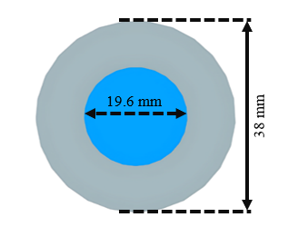
The DPHE comprises a circular outer tube and a longitudinally corrugated inner tube. The three-dimensional internal circular model of the DPHE exhibits four distinct cases, as illustrated in Figure 1. The overall length of the tube remains constant at 2 meters. The diameter of the inner tube is 19.6 mm, while the outer tube diameter measures 38 mm, as depicted in Figure 2. The corrugation width is 5 mm, with a height of 2 mm, consistent across all cases.
Case 1 involves a smooth tube utilized initially for validation purposes and subsequently for compression testing. Case 2 features a four-sided longitudinal corrugation that extends through the surface of the inner tube, except for 5 mm on both sides. Case 3 incorporates longitudinal corrugations with a length of 50 mm and an interval of 45 mm. Case 4 presents a similar geometry to case 3, with the exception that the interval is rotated at 12.5 degrees to enhance mixing.
Figure 1. Inner tube geometrical dimensions
Figure 2. Geometrical dimensions of outer and inner tubes
2.2 Numerical model and boundary conditions
A comprehensive three-dimensional analysis of turbulent flow was conducted for a DPHE, utilizing the standard k-ε (k-epsilon) model within ANSYS Fluent. This model was chosen due to its demonstrated robustness and precision in fully developed internal turbulent flows, particularly where rotation, separation, and adverse pressure gradients. Moreover, this model has been shown to have superior results compared to alternative turbulence models [27]. The second-order upwind scheme was employed to discretize the equations governing energy, turbulence, and turbulent kinetic energy, as well as the terms related to momentum and pressure gradients. The residual was established at 10-6, implementing a coupled velocity–pressure scheme [28].
The analysis is conducted across five different Reynolds numbers, ranging from 6000 to 40000, with a constant mass flow rate for each case, indicating fully developed turbulent flow [22, 25]. It is assumed that the fluid flow is steady and incompressible. The physical properties of the fluid, based on temperature, are considered constant to eliminate additional complexities. Water in its liquid state is employed as the working fluid. Furthermore, the wall thicknesses of the inner and outer tubes are regarded as zero, except for the wall of the inner tube, which separates hot and cold water [18].
A velocity inlet boundary condition was applied to both streams. Hot water at 353 K entered the inner tube, while cold water at 298 K entered the outer tube in a counter-flow configuration [10]. Static pressure is considered to be atmospheric at both tube outlets. No-slip boundary conditions are applied. The inner wall between the two streams allowed for conjugate heat transfer, while the outer surface of the outer tube was assumed to be adiabatic. The flow was modeled as a steady state, and gravitational effects were neglected [29].
2.3 Mesh independence and validation
Mesh independence is a crucial step in the numerical model for obtaining precise results and determining the output time. The mesh utilizes a tetrahedral structure. The near-wall grid is achieved through 15 inflation layers with a growth rate of 1.2, yielding refined results. Further, the skewness is 0.26, and the orthogonal quality is 0.727. These values are consistent with previous CFD studies [28]. To mitigate the impact of mesh elements on fluid flow simulations, an analysis of the element quantity was conducted, ranging from approximately 1.5 million to 5 million elements. The influence of mesh element size on the Nusselt number and the friction factor is analyzed, as shown in Figures 3 and 4, respectively.

Figure 3. Mesh independence for the Nusselt number
The mesh independence analysis was performed for case 3 at a Reynolds number of 6000. Figure 3 shows that at 1.5 million elements, both the Nusselt number and friction factor decrease significantly, then increase as the mesh is refined. Ultimately, at mesh sizes of 3.4 million and 4.5 million, these values stabilize. To achieve accurate results while minimizing computational effort, a 3.4 million-element mesh was chosen for this simulation. The grid parameters were carefully selected to accurately capture the near-wall boundary layer, ensure stable convergence, and obtain mesh-independent results.

Figure 4. Mesh independence for the friction factor

Figure 5. Validation of Nusselt number

Figure 6. Validation of the friction factor
To validate the numerical accuracy, a comparative study was conducted on Case 1, which involves a smooth tube. The parameters of this comparison are the Nusselt number and the friction factor. Water was used as the working fluid in this validation as well. The Nusselt number was validated with experimental data cited by Eiamsa-ard et al. [10]. Additionally, the results were compared with the empirical Dittus-Boelter correlation. The extreme discrepancy between the presented data and experimental results is approximately 5%. Furthermore, the extreme error rate detected between the Dittus-Boelter correlation and the simulated data is around 3%, as illustrated in Figure 5. Additionally, the Darcy friction coefficient was computed and compared to the Blasius friction factor correlation, as shown in Figure 6. It can be observed that the extreme error between our simulation predictions and the Blasius friction factor correlation is 8.5%, consistent with previous literature [28].
This section delineates the impact of geometric modifications on the Nusselt number and the Darcy friction factor. A simulation analysis was performed on three varieties of longitudinal corrugation. Furthermore, a comparative study was conducted against a smooth tube, focusing on the Nusselt number and the friction factor. The analysis encompasses the Reynolds number range from 6,000 to 40,000.
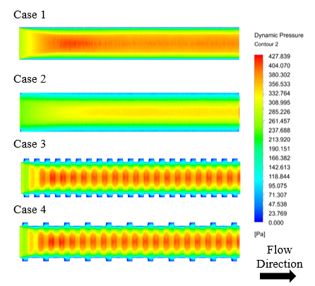
Figure 7 depicts the dynamic contour of the inner tube of DPHE. The dynamic pressure contour offers essential insights into flow acceleration, separation, and recirculation zones, which contribute to understanding the geometrical impact on the friction factor and Nusselt number [30]. In Case 1, a smooth and stable flow pattern is observed, with stable red regions indicating effective heat transfer and fewer blue regions representing lower pressure drops. For Case 2, the red regions are more dispersed, resulting in a reduced pressure gradient. In Cases 3 and 4, darker red and blue zones are present near each corrugation, signifying an increase in the friction factor. Additionally, elevated turbulence and mixing near the wall significantly enhance the Nusselt number. Case 4 features similar corrugations to Case 3, except that half of the corrugation is rotated at an angle of 12.5 degrees on the surface of the inner tube.
Figure 7. Contours of the dynamic pressure for all cases at Re = 40,000
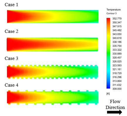
Figure 8. Contours of the temperature for all cases at Re = 40,000
Figure 8 illustrates the temperature contour, which aids in identifying hot and cold zones, the thermal boundary layer, and the effectiveness of the heat exchanger. In Case 1, a thick thermal boundary layer develops and gradually extends downstream, thereby limiting mixing. Case 2 exhibits a low temperature gradient, which results in a lower Nusselt number. In Cases 3 and 4, the temperature drops sharply, and a noticeable transition from red to blue occurs compared to previous cases. The temperature drops indicate mixing, leading to higher Nusselt numbers. Case 4 shows a smaller red zone compared to Case 3, demonstrating the advantage of using scattered corrugation over inline configurations.
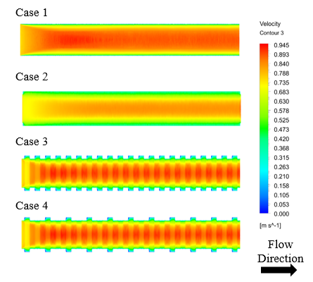
Figure 9. Contours of the velocity magnitude for all cases at Re = 40,000
Figure 9 illustrates the velocity contours, which show the boundary layer thickness and the distribution of velocity along the axis, providing insight into the frictional characteristics within the tube. As observed in Case 1, the boundary layer along the tube is smooth, resulting in a lower friction value. In Case 2, a larger green boundary layer is present, leading to a lower Nusselt number. Cases 3 and 4 exhibit pronounced red and green patterns, indicating a better Nusselt number, as a consequence of a higher friction factor. Furthermore, Case 4 demonstrates a thinner boundary layer compared to Case 3, which correlates with an improved Nusselt number.
The Nusselt number ratio, friction factor ratio, and Thermal Enhancement Factor (TEF) are presented in Table 1 for the investigated cases relative to the smooth tube. The results show that the maximum heat transfer enhancement, approximately 30%, occurs in Case 4 (LC-SR tube) at a Reynolds number of 6,000, with the enhancement ratio gradually decreasing as the Reynolds number increases. This trend agrees with previously reported findings [11], indicating that the relative effect of surface corrugations diminishes at higher flow regimes due to reduced turbulence intensity. In Case 2, which employs straight corrugations, no significant improvement is observed because the flow alignment with the corrugation fails to induce strong fluid mixing. In contrast, Case 3, featuring a 50 mm longitudinal corrugation with a 45 mm spacing, exhibits an 11–23% increase in the Nusselt number, attributed to the generation of secondary flow and enhanced mixing. The highest thermal enhancement is recorded in Case 4, which employs scattered corrugations of the same geometry. This configuration effectively disrupts the boundary layer and promotes fluid recirculation, leading to superior heat transfer performance compared to inline arrangements [31].
The friction factor ratio, also illustrated in Table 1, shows an approximately linear decrease with increasing Reynolds number, consistent with previous studies [29]. The maximum friction ratio of 22% is observed in Case 4 at Re = 6,000, reflecting the greater flow resistance caused by the scattered corrugations. Meanwhile, Case 2 exhibits the lowest friction factor (minimum ratio of 0.64) due to its larger flow area and lower wall velocity gradient. Cases 3 and 4 have comparable friction factor ratios, suggesting that the arrangement of corrugations exerts minimal influence on frictional losses [31].
The Thermal Enhancement Factor (TEF), also included in Table 1, serves as a comprehensive indicator of the overall performance of the heat exchanger, accounting for both convective enhancement and frictional penalties [30]. The TEF decreases with increasing Reynolds number, a trend consistent with prior research [11]. The highest TEF value of 1.22 is obtained in Case 4 at Re = 6,000, followed by 1.16 for Case 3 and 1.13 for Case 2, confirming that the scattered corrugation configuration achieves the most effective balance between heat transfer improvement and pressure drop.
Table 1. Summary of Nu/Nu0, f/f0 and TEF for all the cases
|
Reynolds Number |
|||||
|
|
6,000 |
10,000 |
20,000 |
30,000 |
40,000 |
|
f2/f0 f3/f0 f4/f0 |
0.70 1.19 1.22 |
0.67 1.20 1.21 |
0.64 1.18 1.20 |
0.67 1.15 1.17 |
0.71 1.16 1.17 |
|
Nu2/Nu0 Nu3/Nu0 Nu4/Nu0 |
1.00 1.23 1.30 |
0.91 1.19 1.28 |
0.90 1.14 1.23 |
0.89 1.12 1.22 |
0.89 1.11 1.20 |
|
TEF2 TEF3 TEF4 |
1.13 1.16 1.22 |
1.04 1.12 1.20 |
1.04 1.08 1.16 |
1.02 1.07 1.16 |
1.00 1.06 1.14 |
This study undertook a numerical investigation examining the Nusselt number and friction factor utilizing three types of longitudinal corrugation in DPHE. The five distinct Reynolds numbers considered range from 6,000 to 40,000. This numerical study demonstrated strong consistency with experimental data and empirical correlations, thereby confirming the model's validity. The main conclusions of this study are:
The authors gratefully acknowledge Qassim University, represented by the Deanship of Graduate Studies and Scientific Research, for the financial support for this research under the number (QU-J-PG-2-2025-56825) during the academic year 1446 AH / 2024 AD.
|
C1, C2 |
turbulence model constants, – |
|
dh |
hydraulic diameter, m |
|
f |
darcy friction factor, – |
|
f₀ |
Blasius friction factor, – |
|
Gk |
Production of turbulent kinetic energy, J·s⁻¹·m⁻³ |
|
H |
heat transfer coefficient, W·m⁻²·K⁻¹ |
|
K |
Thermal conductivity, W·m⁻¹·K⁻¹ |
|
k |
turbulent kinetic energy, m2·s⁻2 |
|
L |
Tube length, m |
|
Nu |
Nusselt number, – |
|
Nu₀ |
Nusselt number for smooth tube, – |
|
p |
Pressure, Pa |
|
Pr |
Prandtl number, – |
|
Re |
Reynolds number, – |
|
T |
Temperature, K |
|
TEF |
Thermal Enhancement Factor, – |
|
t |
Time, s |
|
U, V, W |
Velocity components in x, y, z directions, m·s⁻¹ |
|
U’, V’, W’ |
Fluctuated velocity components, m·s⁻¹ |
|
Ū |
Mean velocity, m·s⁻¹ |
|
Greek symbols |
|
|
ε |
Dissipation rate of turbulent kinetic energy, m²·s⁻³ |
|
μ |
Dynamic viscosity, Pa·s |
|
μₜ |
Turbulent viscosity, Pa·s |
|
ρ |
Density, kg·m⁻³ |
|
σK |
Turbulent Prandtl number for k, – |
|
σε |
Turbulent Prandtl number for ε, – |
|
σT |
Turbulent Prandtl number for energy, – |
[1] A. International Energy. (2024). World Energy Outlook 2024. International Energy Agency (IEA), Paris, France. https://www.iea.org/reports/world-energy-outlook-2024.
[2] Davenport, C., Singer, B., Mehta, N., Lee, B., et al. (2024). AI, data centers and the coming US power demand surge. Goldman Sachs, 26.
[3] Ding, Y., Guo, Q., Guo, W., Chu, W., Wang, Q. (2024). Review of recent applications of heat pipe heat exchanger use for waste heat recovery. Energies, 17(11): 2504. https://doi.org/10.3390/en17112504
[4] Mansour, M.M., Hamood, H.M., Lafta, A.M., Nashee, S.R., Shkarah, A.J. (2024). Enhancing the efficacy of adsorption-based carbon storage systems: A finite element analysis approach. International Journal of Energy Production and Management, 9(1): 19-24. https://doi.org/10.18280/ijepm.090103
[5] Al-Azawiey, S.S., Mohamed, M.M., Arifin, A.B. (2023). Effectiveness of PV/T passive natural air cooling by backside attached fins. International Journal of Energy Production and Management, 8(2): 55-62. https://doi.org/10.18280/ijepm.080201
[6] Agarwal, A., Ilunga, M., Tempa, K., Humagai, B.K. (2024). CFD analysis of solar air heater using V-shaped artificial roughness to attain heat transfer enhancement. International Journal of Energy Production and Management, 9(3): 171-180. https://doi.org/10.18280/ijepm.090306
[7] Gabir, M.M., Alkhafaji, D. (2021). Comprehensive review on double pipe heat exchanger techniques. Journal of Physics: Conference Series, 1973(1): 012013. https://doi.org/10.1088/1742-6596/1973/1/012013
[8] Gabir, M.M., Albayati, I.M., Hatami, M., Alkhafaji, D. (2024). An experimental investigation of the convective heat transfer augmentation in U-bend double pipe heat exchanger using water-MgO-Cmc fluid. Scientific Reports, 14(1): 12442. https://doi.org/10.1038/s41598-024-63043-6
[9] Rasul, M.G., Ahmed, S., Sattar, M.A., Jahirul, M.I. (2023). Hydrodynamic performance assessment of photocatalytic reactor with baffles and roughness in the flow path: A modelling approach with experimental validation. Heliyon, 9(9): e19623. https://doi.org/10.1016/j.heliyon.2023.e19623
[10] Eiamsa-ard, S., Pethkool, S., Thianpong, C., Promvonge, P. (2008). Turbulent flow heat transfer and pressure loss in a double pipe heat exchanger with louvered strip inserts. International Communications in Heat and Mass Transfer, 35(2): 120-129. https://doi.org/10.1016/j.icheatmasstransfer.2007.07.003
[11] Alwatban, A. (2024). Numerical investigation of flow and thermal fields in heat exchanger with two porous vertical baffles. International Journal of Heat and Technology, 42(5): 1517-1524. https://doi.org/10.18280/ijht.420504
[12] Pordanjani, A.H., Aghakhani, S., Afrand, M., Mahmoudi, B., Mahian, O., Wongwises, S. (2019). An updated review on application of nanofluids in heat exchangers for saving energy. Energy Conversion and Management, 198: 111886. https://doi.org/10.1016/j.enconman.2019.111886
[13] Sarafraz, M.M., Safaei, M.R., Goodarzi, M., Yang, B., Arjomandi, M. (2019). Heat transfer analysis of Ga-In-Sn in a compact heat exchanger equipped with straight micro-passages. International Journal of Heat and Mass Transfer, 139: 675-684. https://doi.org/10.1016/j.ijheatmasstransfer.2019.05.057
[14] Li, J., Dang, C., Hihara, E. (2019). Heat transfer enhancement in a parallel, finless heat exchanger using a longitudinal vortex generator, Part A: Numerical investigation. International Journal of Heat and Mass Transfer, 128: 87-97. https://doi.org/10.1016/j.ijheatmasstransfer.2018.06.049
[15] Omidi, M., Farhadi, M., Jafari, M. (2017). A comprehensive review on double pipe heat exchangers. Applied Thermal Engineering, 110: 1075-1090. https://doi.org/10.1016/j.applthermaleng.2016.09.027
[16] Sabau, A.S., Bejan, A., Brownell, D., Gluesenkamp, K., et al. (2020). Design, additive manufacturing, and performance of heat exchanger with a novel flow-path architecture. Applied Thermal Engineering, 180: 115775. https://doi.org/10.1016/j.applthermaleng.2020.115775
[17] Dixit, T., Al-Hajri, E., Paul, M.C., Nithiarasu, P., Kumar, S. (2022). High performance, microarchitected, compact heat exchanger enabled by 3D printing. Applied Thermal Engineering, 210: 118339. https://doi.org/10.1016/j.applthermaleng.2022.118339
[18] Huu-Quan, D., Rostami, A.M., Rad, M.S., Izadi, M., Hajjar, A., Xiong, Q. (2021). 3D numerical investigation of turbulent forced convection in a double-pipe heat exchanger with flat inner pipe. Applied Thermal Engineering, 182: 116106. https://doi.org/10.1016/j.applthermaleng.2020.116106
[19] Mozafarie, S.S., Javaherdeh, K., Ghanbari, O. (2021). Numerical simulation of nanofluid turbulent flow in a double-pipe heat exchanger equipped with circular fins. Journal of Thermal Analysis & Calorimetry, 143(6): 4299-4311. https://doi.org/10.1007/s10973-020-09364-w
[20] Dizaji, H.S., Jafarmadar, S., Mobadersani, F. (2015). Experimental studies on heat transfer and pressure drop characteristics for new arrangements of corrugated tubes in a double pipe heat exchanger. International Journal of Thermal Sciences, 96: 211-220. https://doi.org/10.1016/j.ijthermalsci.2015.05.009
[21] Sruthi, B., Sasidhar, A., Surendra Kumar, A., Sahu, M.K. (2021). Comparative analysis of corrugation effect on thermohydraulic performance of double-pipe heat exchangers. Heat Transfer, 50(5): 4622-4642. https://doi.org/10.1002/htj.22092
[22] Fadhil, N.A., Al-Dabagh, A.M., Hatem, F.F. (2023). Numerical investigation of heat transfer and pressure drop characteristics in a double pipe heat exchanger with corrugated tubes and rod baffles at various Reynolds numbers. International Journal of Heat and Technology, 41(3): 591-601. https://doi.org/10.18280/ijht.410311
[23] Zheng, L., Xie, Y., Zhang, D. (2017). Numerical investigation on heat transfer performance and flow characteristics in circular tubes with dimpled twisted tapes using Al2O3-water nanofluid. International Journal of Heat and Mass Transfer, 111: 962-981. https://doi.org/10.1016/j.ijheatmasstransfer.2017.04.062
[24] Nakhchi, M.E., Esfahani, J.A. (2019). Performance intensification of turbulent flow through heat exchanger tube using double V-cut twisted tape inserts. Chemical Engineering and Processing-Process Intensification, 141: 107533. https://doi.org/10.1016/j.cep.2019.107533
[25] Kurşun, B. (2019). Thermal performance assessment of internal longitudinal fins with sinusoidal lateral surfaces in parabolic trough receiver tubes. Renewable Energy, 140: 816-827. https://doi.org/10.1016/j.renene.2019.03.106
[26] Bhattacharyya, S., Vishwakarma, D.K., Srinivasan, A., Soni, M.K., Goel, V., Sharifpur, M., Ahmadi, M.H., Issakhov, A., Meyer, J. (2022). Thermal performance enhancement in heat exchangers using active and passive techniques: A detailed review. Journal of Thermal Analysis and Calorimetry, 147(17): 9229-9281. https://doi.org/10.1007/s10973-021-11168-5
[27] Shaheed, R., Mohammadian, A., Kheirkhah Gildeh, H. (2019). A comparison of standard k–ε and realizable k–ε turbulence models in curved and confluent channels. Environmental Fluid Mechanics, 19(2): 543-568. https://doi.org/10.1007/s10652-018-9637-1
[28] Jasim, H.A., Mohammed, A.A., Hawas, M.N. (2025). Numerical investigation of heat transfer enhancement and friction characteristics in a square duct with diagonal tape and multi-V ribs under turbulent flow. International Journal of Heat and Technology, 43(4): 1491-1498. https://doi.org/10.18280/ijht.430426
[29] Edan, I.L., Alsalhy, M.J., Hussein, B.A., Ouda, A.A. (2025). Numerical prediction for turbulent flow and heat transfer in different configurations U-tube heat exchanger by using twisted tape. International Journal of Heat and Technology, 43(4): 1521-1528. https://doi.org/10.18280/ijht.430429
[30] Wang, N., Ghoushchi, S.P., Sharma, K., Elbadawy, I., Mouldi, A., Loukil, H., Deifalla, A.F. (2023). Thermal performance enhancement in a double tube heat exchanger using combination of bubble injection and helical coiled wire insert. Case Studies in Thermal Engineering, 52: 103722. https://doi.org/10.1016/j.csite.2023.103722
[31] Falih, A.H., Khalaf, B.S., Freegah, B. (2024). Investigate the impact of dimple size and distribution on the hydrothermal performance of dimpled heat exchanger tubes. Frontiers in Heat and Mass Transfer, 22(2): 597-613. https://doi.org/10.32604/fhmt.2024.049812