Anton Nugroho![]() | Wawan Aries Widodo*
| Wawan Aries Widodo*![]() | Is Bunyamin Suryo
| Is Bunyamin Suryo![]()
© 2025 The authors. This article is published by IIETA and is licensed under the CC BY 4.0 license (http://creativecommons.org/licenses/by/4.0/).
OPEN ACCESS
This study addresses the challenges of excessive heat within the engine room of Landing Ship Tank (LST) warships, directly impacting the comfort and safety of the crew. The optimal temperature range is between 23℃ to 26℃; however, the emissions of CO and CO₂ leakage from the engine contribute to rising temperatures and health risks. The study uses Computational Fluid Dynamics (CFD) techniques to evaluate the thermal behavior and airflow under various engine load conditions. Findings show that higher engine loads increase CO and CO₂ leakage, raising temperatures. Strategies such as increasing blower capacity and optimizing fan placement can effectively reduce temperatures and enhance air distribution. The research underscores the importance of adaptive ventilation systems and recommends automated, real-time solutions to improve thermal comfort, safety, and energy efficiency. A comparative review of studies from 2020 to 2024 further supports these findings, emphasizing the necessity for innovative ventilation designs in maritime environments.
computational fluid dynamics, landing ship tank, thermal comfort, ventilation system
Landing Ship Tank (LST) class warships are ships capable of docking at the low tide line farthest from the target beach so they can land at the beach location. This landing operation may provide logistical assistance to isolated disaster locations. This ship is designed to transport heavy combat vehicles like the Leopard main battle tank and BMP 3F tanks during amphibious operations. Excessive heat exposure in the ship's engine room causes discomfort to the working crew there. The temperature considered comfortable for workers in the engine room of this ship is between 23℃ to 26℃, while the recommended humidity range is between 40% and 60%. CO and CO₂ leaks can cause an increase in temperature in the engine room, affecting engine performance and safe working conditions for the crew. These temperature changes can also impact humidity levels in the engine room. CO and CO₂ leaks cause crew members to experience respiratory problems, dizziness, weakness, and nausea. The most severe impact of the condition is prolonged exposure to excessive carbon monoxide will result in death [1].
The air ventilation system is a vital element in every ship. Air ventilation is used according to the needs of each vessel or ship model. Some rely on natural ventilation systems, some use mechanical ventilation or fans, and some use Air conditioner (AC) systems [2]. To dissipate heat, it is necessary that compartments using gas or liquid mediums are quipped with mechanical air ventilation or fans. Air exchange on ships, especially in the engine room, is essential because it reduces accidents or fires in the ship's engine room. The air handling unit (AHU) is a system of air ventilation that offers ease of operation and maintenance [3]. Engine room ventilation is crucial for marine engineering, ensuring efficiency and safety by maintaining temperatures, providing combustion air, and preventing fire and toxic gas risks. Recent studies emphasize the role of Computational Fluid Dynamics (CFD) in optimizing these systems [1]. CFD helps analyze airflow and temperature distributions, as shown by Salmani et al. [4] who demonstrated energy savings through optimized ventilation. Similarly, Chen et al. [5] found that adjusting air outlet positions improved ventilation efficiency using numerical simulations. These studies highlight CFD's value in enhancing engine room ventilation design.
The comfort index and thermal pressure in a ship's engine room are essential for maintaining operational efficiency and safety. This index measures thermal comfort, considering key variables such as temperature, humidity, and airflow. In engine rooms, rising temperatures and poor ventilation can cause discomfort and fatigue, highlighting the need for robust thermal management. Research indicates that engine rooms frequently experience high temperatures, requiring crew members to take breaks to alleviate thermal stress. Orosa et al. [6] emphasize that even minimal work in such conditions may necessitate up to 15-minute rest intervals due to fatigue. This finding underscores the importance of monitoring and managing thermal conditions to boost comfort and productivity.
Ventilation is critical for reducing thermal pressure within engine rooms. Alizadeh et al. [7] note that proper ventilation affects temperature distribution, reducing heat concentration and overall conditions. CFD modeling has identified hot spots that benefit from targeted ventilation [4]. Such insights support Newton et al.'s findings that optimized airflow lowers intake temperatures and enhances cooling efficiency. The design of these systems must also consider specific thermal loads and engine room needs. He [8] advocates for automated temperature control that adjusts ventilation based on real-time data, thereby cutting energy waste while ensuring adequate cooling. Orosa et al. similarly recommend a comprehensive approach to optimizing ventilation for energy efficiency and risk mitigation [6]. Managing the comfort index in engine rooms involves addressing thermal pressure through effective ventilation and environmental controls. Advanced modeling and intelligent systems can improve these conditions, enabling crew members to work safely and efficiently.
Moreover, the design of ventilation systems must prioritize fire safety. Wang's research indicates that the structure of ventilation and airflow velocities directly influence fire dynamics within the engine room, affecting the mass loss rates of leaked fuels and the behavior of flames during incidents [9]. This finding is critical, as poor ventilation can accumulate flammable gases, increasing the risk of ignition and fire spread. It is essential to have a well-designed ventilation system that can effectively manage smoke and heat during a fire. It is emphasized that mechanical ventilation can significantly affect the temperature and spread of smoke during a fire [10, 11]. Operational aspects of ventilation systems are critical, besides fire safety. He suggested that automated temperature control systems for engine rooms can reduce energy use, replacing manual fan operations for greater efficiency [8]. The ventilation inlet and outlet configurations design significantly impacts heat concentration and airflow, as noted by Alizadeh et al. [7]. Well-designed ventilation enhances crew comfort and maintains equipment within safe temperatures. Incorporating these findings can boost energy efficiency and safety in engine room ventilation. As maritime policy focuses on energy conservation, optimizing ventilation is crucial for compliance and performance [6].
The discussion on ship ventilation highlights the importance of design, safety, and operational efficiency. A primary focus is ensuring air quality and thermal comfort for crew and passengers, with research revealing a significant gap in studies on ship ventilation compared to buildings [12]. This gap is particularly relevant for offshore platforms. Advanced technologies, such as the E-Cabin architecture, facilitate real-time monitoring of cabin conditions, thereby improving comfort and energy efficiency [13]. Regarding safety, ventilation is critical in addressing fire hazards, with fire drill models incorporating ventilation considerations to enhance safety protocols [14]. Also, ventilation is crucial in engine rooms, which face challenges related to noise and gas leaks, requiring effective systems to prevent explosion risks and protect health [15].
The discussion on ship ventilation, especially during the COVID-19 pandemic, emphasized the critical role of adequate ventilation in preventing the airborne transmission of the virus. Poorly ventilated spaces were identified as high-risk areas for spreading SARS-CoV-2, with research highlighting the link between inadequate ventilation and respiratory infections [16]. This risk is particularly concerning in the confined spaces of ships [17]. Studies stressed the importance of regular maintenance and proper configuration of ventilation systems to minimize infection risks [18]. ASHRAE also updated its guidelines to reduce airborne transmission of COVID-19 [19]. Natural ventilation was recommended as a complementary strategy, enhancing air quality and reducing virus transmission [20]. During the pandemic, there was a focus on developing low-cost ventilators to meet healthcare demands, with engineers and healthcare professionals collaborating on open-source designs [21].
The 2021 discussion on ship ventilation, influenced by the COVID-19 pandemic, emphasized the importance of effective systems to prevent airborne transmission, as seen in the outbreak on the Diamond Princess. Poor ventilation was associated with the virus's rapid spread, underscoring the need to redesign ship ventilation for better air quality and infection control [22, 23]. Traditional HVAC systems, designed for comfort, often do not provide sufficient air changes per hour (ACH) to control airborne infections [24]. Increasing ACH and using efficient air filters can significantly reduce pathogen spread [25]. Advanced technologies, like UV disinfection, have also been proposed to enhance safety [26]. Research also focuses on intelligent cargo-hold ventilation systems, integrating automation for better air management and energy efficiency [27]. Additionally, environmental concerns drive efforts to reduce ship emissions, aligning with IMO goals for sustainable practices and cleaner ventilation technologies.
This study has simulated a basement fire using Autodesk CFD 2020 to test the effectiveness of exhaust fans at various flow rates (20,000 m³/h, 50,000 m³/h, and 100,000 m³/h). The results show that the exhaust fan volume of 100,000 m³/h is the most optimal because at 1200 seconds after the fire, the temperature below 1.4 meters remains below 65℃ with smoke visibility of around 10 meters. This condition supports evacuation and makes it easier for firefighters. Autodesk CFD has proven effective in verifying designs before field implementation [28]. This research has developed a modular COVID-19 testing center at Incheon Airport for rapid detection. The modular facility, designed with negative pressure, was selected for its speed and cost-effectiveness than conventional construction. An energy recovery ventilation (ERV) system and a CFD simulation-based design were applied to overcome energy and condensation challenges commonly found in standard facilities. As a result, the facility was completed in two weeks and met international pressure and ventilation standards [29].
Optimizing ship ventilation is crucial due to its high energy consumption, accounting for 3.5% to 5.5% of a ship's power [4]. Using Computational Fluid Dynamics (CFD), Salmani et al. demonstrated that effective ventilation improves thermal comfort and energy efficiency in ship engine rooms. Additionally, better ventilation helps reduce harmful emissions like NOx and SO2, improving air quality, especially in coastal areas [30]. The physical conditions in engine rooms, such as noise and poor air quality, can harm crew health and performance [31]. Effective ventilation mitigates these risks, improving crew safety and operational efficiency. Furthermore, integrating technologies like thermoprocessors and cooling systems can enhance engine performance, boost fuel efficiency, and reduce emissions [30].
Ventilation systems in machinery rooms are vital for preventing overheating and ensuring proper equipment function. Airflow distribution is also key in controlling fire behavior, requiring optimized ventilation to reduce fire hazards [32]. Research shows that specific ventilation designs improve smoke extraction and fire safety in marine engine rooms while maintaining air quality and reducing hazardous gas accumulation [33]. HVAC systems, the second-largest energy consumers on cruise ships, are a growing concern. Using advanced control strategies, energy management systems help reduce energy use while maintaining comfort [34]. As emission regulations tighten, improved ventilation is also needed to manage air quality on board and at ports, balancing safety, comfort, and environmental compliance [35, 36].
Engine room ventilation systems are crucial for safety, particularly in managing hazardous gases like hydrogen. Gao's research highlights the importance of optimizing ventilation to reduce hydrogen-related risks, offering insights into ventilation volume and sensor placement [37]. Effective ventilation is essential as hydrogen technologies continue to advance in the maritime industry. He proposes automated temperature control systems to improve efficiency and reduce energy use compared to manual fan operations [8]. Similarly, Paulson's work on integrating renewable energy, such as solar power, into ventilation systems supports sustainability initiatives in maritime operations [38]. Additionally, Bruno's study on heat recovery from LNG processes demonstrates the potential for improving energy efficiency and ventilation in engine rooms [39].
Researchers have conducted several review studies on ventilation systems in ship engines. To prevent the spread of disease, the ship's ventilation system was evaluated through a review process [40]. A review conducted in 2023 [41] comprehensively assessed the marine incident and provided recommendations for future research. In 2024, operational safety was reviewed [42], focusing on noise reduction techniques for ship employees. Additionally, in 2024, mathematical and bibliometric models were evaluated [1] to enhance air ventilation systems. Risk assessment and safety zone checks were also conducted in 2024 [43] for ships utilizing LNG. This research presents a case study on air ventilation modeling in a ship's engine room using a CFD approach. The novelty of this paper lies in its analysis of CO and CO₂ leakage, airflow distribution, and temperature contour on the engine room plane. A comparative review of the Comfort Index and Engine Room Heat Pressure has also been conducted. Integrating this case study with the comparative review provides valuable insights for predicting and optimizing the ship's engine room ventilation system, thereby reducing heat pressure and exhaust gas leakage. Consequently, the safety and comfort of the crew can be improved and maintained sustainably.
2.1 Simulation approach
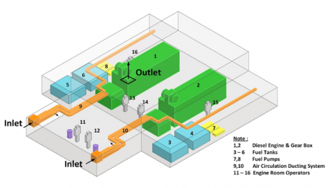
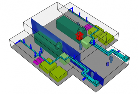
This study uses numerical methods to model and simulate complex fluid dynamics in a ship's engine room. The methodology incorporates computational fluid dynamics (CFD) techniques, enabling the analysis of thermal and airflow behavior under diverse boundary conditions. Pre-processing involves inputting data and configurations necessary to define the simulation parameters and computational environment. This stage includes several steps, beginning with the creation of geometry. A three-dimensional geometric model of the engine room has been generated, seamlessly integrating various boundary conditions such as inlets, outlets, and wall specifications. These boundary conditions represent key components, including the engine, gearbox, and separator, allowing the model to capture the reality of the physical space as closely as possible. The detailed setup allows for more precise airflow and thermal dynamics simulations within the engine room, as illustrated in Figure 1 below.
Figure 1. Geometry set-up and domain simulation
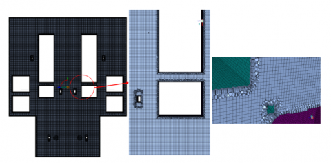
The geometrical model is discretized into small elements or grids, a process called meshing. The mesh has a significant influence on the accuracy and computational cost of the simulation. Grid independence tests were conducted to ensure that mesh size did not influence the results. A best-grid configuration of approximately 4.2 million cells was selected with a trade-off between accuracy and computation. Mesh density was determined considering this balance, aiming for accuracy without overburdening computational resources. Figure 2 illustrates the meshing results.
Figure 2. Meshing (Top view)
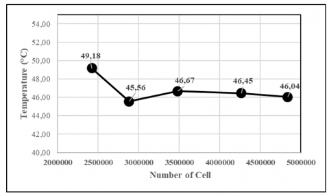
Figure 3. Grid independency test
The Grid Independence Test (GIT) ensures that the solution obtained is independent of the mesh size used. This test is achieved by comparing the solution results from a coarse mesh to those from a finer mesh. If the solution does not vary significantly with changes in mesh size, it can be considered grid-independent. The GIT was performed at coordinates x = 2.25 m, y = 1.8 m, and z = 8.65 m under 100% engine load conditions by comparing the temperature values at these points. The table shows that the temperature values did not change significantly with mesh sizes exceeding 4.2 million cells. Since the temperature variation was relatively small, a mesh with 4,265,479 cells was selected. The results of the Grid Independence Test, along with temperature variation graphs for each cell count, are presented in Table 1 and Figure 3.
Table 1. Grid Independency
|
Index |
Cell |
Temperature (°C) |
Relative Error (%) |
|
Mesh A |
2422640 |
49.19 |
- |
|
Mesh B |
2880836 |
45.56 |
7.4% |
|
Mesh C |
3480678 |
46.67 |
2.4% |
|
Mesh D |
4265479 |
46.45 |
0.5% |
|
Mesh E |
4836081 |
46.04 |
0.9% |
The quality of meshing in the air ventilation system of the ship's engine room, as depicted in the Figure 2, demonstrates careful consideration of slope, aspect ratio, and size. The mesh elements perfectly capture the structural features, ensuring that the physical geometry is accurately represented. The aspect ratios of the elements are mostly regular, with square or slightly rectangular shapes that promote numerical stability for simulations. The element size varies accordingly, having smaller elements in critical areas like edges and corners to capture detailed features, and coarser elements in larger flat areas to optimize computational efficiency. Overall, the meshing quality is well-balanced, providing a solid foundation for accurate and efficient simulations.
The processing stage involves solving the fundamental fluid flow and heat transfer equations, such as iterative simulation updates to reach convergence. Key steps in this stage include configuring the solver settings to use a second-order scheme, which enhances accuracy in predicting gradient, pressure, and momentum fields. The pressure-velocity coupling scheme is defined, and a second-order upwind scheme for all transport variables is applied; both provide computational stability and precision. For turbulence modeling, the k-ε RNG turbulence model is employed to capture the turbulent flow inside the engine room [5]. Specific details, such as the treatment of near-wall regions and buoyancy effects, are tailored to the physical scenario, ensuring a realistic simulation of the fluid's thermal and dynamic behavior [4].
For the transport equation for turbulent kinetic energy (k) is:
$\frac{\partial k}{\partial t}+U_j \frac{\partial k}{\partial x_j}=P_k-\varepsilon+\frac{\partial}{\partial x_j}\left(v_t \frac{\partial k}{\partial x_j}\right)+S_k$ (1)
For transport equation for turbulent dissipation rate $(\varepsilon)$ is:
$\frac{\partial \varepsilon}{\partial t}+U_j \frac{\partial \varepsilon}{\partial x_j}=C_{\varepsilon 1} \frac{\varepsilon}{k} P_k-C_{\varepsilon 2} \varepsilon+\frac{\partial}{\partial x_j}\left(v_t \frac{\partial \varepsilon}{\partial x_j}\right)+S_{\varepsilon}$ (2)
For turbulent viscosity is:
$v_t=C_\mu \frac{K^2}{\varepsilon}$ (3)
where, turbulent kinetic energy is $k\left(\mathrm{m}^2/\mathrm{s}^2\right)$, Velocity component in the $j$-th direction ($\mathrm{m}/\mathrm{s}$), Production of turbulent kinetic energy is $P_k\left(\mathrm{m}^2/\mathrm{s}^3\right)$, Turbulence dissipation rate is $\varepsilon$ $\left(\mathrm{m}^2/\mathrm{s}^3\right)$, turbulent viscosity is $v_t\left(\mathrm{m}^2/\mathrm{s}\right)$, The source term for turbulent kinetic energy is $S_k\left(\mathrm{m}^2/\mathrm{s}^3\right)$ and $C_\mu$ is Empirical constant.
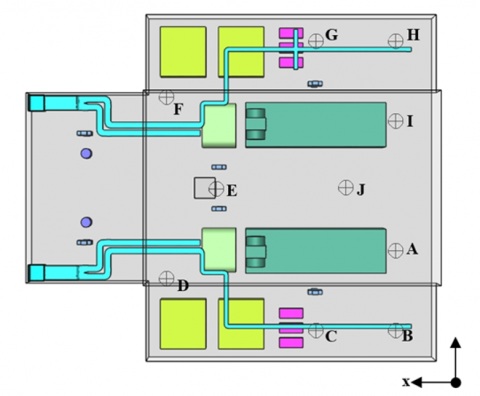
The post-processing stage involves extracting and analyzing data from the simulation. The results include quantitative and qualitative data, e.g., velocity, temperature, and pressure distributions at designated observation points. Data Collection: Quantitative data are collected from specified points within the engine room, as outlined in Table 2 and Figure 4. This data includes temperature profiles, velocity distributions, and pressure contours, which are used to evaluate the effectiveness of the ventilation system. Qualitative analysis: besides the numerical data, visual outputs such as velocity vectors, temperature contours, and streamlines are generated. These graphical representations provide insights into flow patterns and heat distribution, crucial for assessing ventilation performance under different operating conditions.
Table 2. Designated observation points
|
Points |
X (m) |
Y (m) |
Z (m) |
|
A |
2 |
1.8 |
5.5 |
|
B |
2 |
1.8 |
1.5 |
|
C |
6 |
1.8 |
1.5 |
|
D |
13.5 |
1.8 |
4.1 |
|
E |
11 |
1.8 |
8.6 |
|
F |
13.5 |
1.8 |
13.2 |
|
G |
6 |
1.8 |
16 |
|
H |
2 |
1.8 |
16 |
|
I |
2 |
1.8 |
12 |
|
J |
4.25 |
1.8 |
8.65 |
Figure 4. Location of observation points in the engine room
2.2 Experimental approach
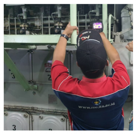
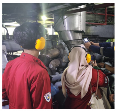
Experimental studies were conducted by collecting field data on the Landing Ship Tank (LST) Warship to gather initial data before validating it through simulations with predetermined parameters, as shown in Figure 5. The authors employed two tools for collecting heat stress data: The Heat Stress Apparatus (TSI/3M Quest Technologies QUES Temp 48 N Waterless Wet Bulb) and the Flir E8-XT Thermal Imaging Camera. The Heat Stress Apparatus is a portable, fast, and accurate device that measures individual heat stress potential based on environmental conditions, enabling control of independent variables via a control group. Meanwhile, the Flir E8-XT, on the other hand, is a thermal imaging camera designed for industrial diagnostics and inspection, having a resolution of 320×240 pixels, providing detailed visuals to detect issues related to heat and humidity. Both tools undergo annual calibration for optimal accuracy. Additionally, the author utilized the TSI Q-Trak 7545 with the IAQ 982 Probe to monitor CO and CO₂ leaks, as illustrated in Figure 6. This instrument offers a rapid assessment of indoor air quality, including CO, CO₂, temperature, and humidity measurements, which are essential for evaluating environmental comfort and safety. This instrument, too, is calibrated annually to maintain optimal performance.
The study validated the simulation results by comparing them with experimental data and reference literature to ensure the reliability of the numerical model. The grid dependence test was conducted, confirming mesh independence, while the suitability of the turbulence model was evaluated by comparing the predicted and observed values across several performance metrics. Validation in this research included temperature measurements taken at various points in the engine room of a Landing Ship Tank class vessel, which were then compared to the simulation results. As shown in Table 3, the simulation results closely match the actual conditions in the ship's engine room.
Figure 5. Data collection using heat stress apparatus
Figure 6. CO and CO2 leak data collection using indoor air quality monitor probe
Table 3. Comparison of reference data and simulation data results
|
Point |
Experimental Data |
Simulation Data |
Error |
|
A |
45.5 |
44.36 |
2.57% |
|
B |
38.6 |
39.50 |
2.28% |
|
C |
39.7 |
40.57 |
2.14% |
|
D |
37.8 |
39.02 |
3.13% |
|
E |
42.9 |
44.03 |
2.57% |
|
F |
38.7 |
37.73 |
2.57% |
|
G |
38.8 |
37.19 |
4.33% |
|
H |
37.1 |
37.68 |
1.54% |
|
I |
45.6 |
43.90 |
3.87% |
|
J |
45.1 |
44.30 |
1.81% |
The validation of simulation results, achieved by comparing them with experimental data and reference literature, is crucial for ensuring the reliability of the numerical model. Despite the grid dependence test confirming mesh independence and the suitability of the turbulence model performance, which has been assessed through various performance metrics, several potential sources of error must be considered. Measurement errors, such as instrument precision and environmental factors, can affect temperature readings. Modeling assumptions, including the choice of turbulence model and boundary conditions, can introduce discrepancies. Numerical errors, despite mesh independence, may arise from discretization methods or solver inaccuracies, while human errors in data entry or interpretation can further impact results. These errors have significant implications for the reliability of the numerical model, opportunities for refinement, informed decision-making, and future research. Recognizing and addressing these sources of error is essential for strengthening the validation process and ensuring accurate simulations.
3.1 The CO and CO₂ leak analysis
The analysis of exhaust gas leakage distribution, particularly CO and CO₂, in the engine room was conducted to predict the trend of airflow velocity, temperature, and pressure distribution. Table 4 outlines the boundary conditions for CO and CO₂ leakage at different engine loads. At 50% load and 550 RPM, CO₂ leakage was measured at 0.015 kg/s, while CO leakage was 0.005 kg/s. When the load increased to 75% with 650 RPM, CO₂ leakage rose to 0.019 kg/s, and CO leakage to 0.006 kg/s. At full engine load (100%) with 751 RPM, CO₂ leakage increased to 0.032 kg/s, and CO leakage increased to 0.01 kg/s. These data indicate a positive correlation between engine load and exhaust gas leakage rates.
The results indicate that as engine load and RPM increase, CO and CO₂ emission levels also rise. This observation aligns with the findings [7], which showed that increasing mechanical workload and engine performance significantly contribute to higher exhaust gas concentrations. A study [44] has supported this conclusion, noting that increased engine activity leads to elevated emission levels, particularly under high-load conditions.
Table 4. Boundary conditions for CO and CO2
|
Load % |
Engine Speed |
ṁ (CO₂ Leakage) |
ṁ (CO Leakage) |
|
50% (1 Engine) |
550 RPM |
0.015 Kg/s |
0.005 Kg/s |
|
75% (1 Engine) |
650 RPM |
0.019 Kg/s |
0.006 Kg/s |
|
100% (1 Engine) |
751 RPM |
0.032 Kg/s |
0.01 Kg/s |
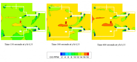
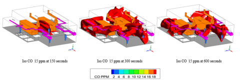
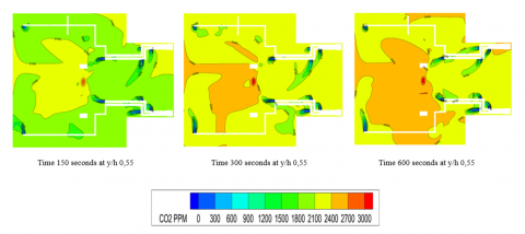
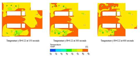
Figures 7 to 11 illustrate contour plots for CO, CO₂, and temperature at various elevations within the engine compartment. Figures 7 and 8 display the CO concentration contour at elevation y/H = 0.55 under full load, revealing significant CO concentrations near the engine, likely due to incomplete combustion at high engine loads. Similarly, Figures 9 and 10 show the CO₂ distribution at the same elevation, with high concentrations primarily near the exhaust manifold. The temperature contours in Figure 12 indicate increased heat concentrations around the engine exhaust system, particularly at full load.
This finding is consistent with the numerical analysis by ref [5], who concluded that increasing engine load results in greater heat dissipation, necessitating an optimized ventilation system to prevent overheating in the engine room. Figures 7 and 9 show the combined distribution of CO and CO₂ at elevation y/H = 0.55, displaying a similar trend of increasing concentrations near engine components and the exhaust. This finding highlights the need for an adequate ventilation system by underlining the importance of air movement to reduce gas buildup and alleviate potential health hazards to engine room personnel [4].
Figure 7. CO contour at elevation y/H=0.55 at 100% load
Figure 8. Iso CO 15 ppm at 150, 300, and 600 seconds
Figure 9. CO2 contour at elevation y/H=0.55 at 100% load
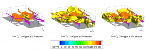
Figure 10. Iso CO2 2400 ppm at 150, 300, and 600 seconds
Figure 11. Temperature y/H=0.22 at 150, 300, and 600 seconds, respectively
Figure 12. Velocity contours on the Y/H=0.38 plane
The observed relationship between engine load and gas leakage significantly impacts marine vessels' operational safety and environmental impact. Increased CO and CO₂ emissions at higher engine loads pose risks to personnel on board and the environment. The accumulation of exhaust gas in confined spaces, such as engine rooms, can lead to hazardous working conditions, thus requiring efficient monitoring and ventilation systems [45]. This study's findings align with those that used advanced monitoring techniques to predict CO₂ concentrations in ship exhaust gas [46]. Utilizing monitoring systems coupled with predictive modeling can aid in the timely identification of hazardous gas levels, allowing for corrective actions to be taken before concentrations reach dangerous thresholds. The temperature distribution results also highlight the importance of effective thermal management in engine rooms. High temperatures, as observed in Figure 7-11, can exacerbate the degradation of engine components, reduce their service life, and increase maintenance costs. Implementing an Internet of Things (IoT)-based exhaust emission monitoring system can improve real-time detection and facilitate proactive exhaust gas management and temperature control [47].
Comparing these leakage levels to industry standards and regulatory limits, the Occupational Safety and Health Administration (OSHA) sets permissible exposure limits (PELs) for CO₂ at 5,000 ppm (time-weighted average) and 30,000 ppm (short-term exposure limit) in workplace atmospheres. For CO, the Environmental Protection Agency (EPA) has established national ambient air quality standards (NAAQS) with a maximum allowable concentration of 9 ppm over 8 hours and 35 ppm over 1 hour. The observed leakage rates in the engine room, particularly under high-load conditions, highlight the need for effective ventilation systems to prevent the accumulation of these gases and ensure compliance with safety standards. This result underscores the importance of optimizing ventilation to mitigate health risks and maintain engine performance.
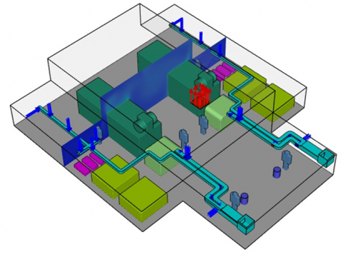
3.2 Air flow distribution in engine room
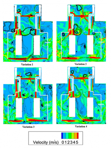
The airflow distribution in the engine room is illustrated in Figure 12, showing significant secondary flows, particularly in high-temperature areas. This phenomenon occurs due to heat accumulation, especially above the main engine, generating significant heat. As a result, eddies form above the engine room as trapped heat circulates, affecting the overall airflow dynamics. This finding aligns with previous studies that also noted the occurrence of secondary flows in high-temperature zones within confined spaces such as the engine room [6, 7].
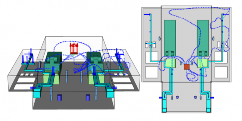
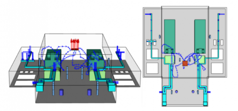
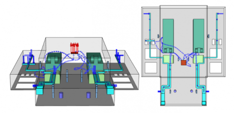
Figures 13 and 14 present the airflow distribution patterns for Variations 1 and 2. The ventilation outlet's airflow reaches the engine room's rear in this configuration. The incoming air, which has a relatively lower temperature than the ambient air inside the engine room, helps reduce the overall temperature, particularly at the rear of the room. This cooling effect reinforces the finding that proper ventilation design can significantly lower local temperatures in high-temperature areas through effective air distribution [5]. In contrast, Variations 3 and 4, as shown in Figures 15 and 16, utilize fans to enhance the airflow pattern. However, this arrangement limits air distribution, as the fans quickly draw airflow from the ventilation ducts, preventing it from reaching deeper areas of the engine room. Consequently, the average temperature inside the engine room increases, leading to counterproductive. This observation is consistent with findings noting that suboptimal fan placement can lead to inefficient cooling in the engine room [4].
Figure 13. Velocity path line of air flow started from Inlet 5 and 14 in Variation 1
Figure 14. Velocity path line for air flow started from Inlet 5 and 14 in Variation 2
Figure 15. Air flow from Inlets 5 and 14 in Variation 3
Figure 16. Air flow from Inlet 5 and 14 in Variation 4
As revealed in Variations 3 and 4, the placement of the exhaust fan affects cooling performance significantly. The proximity of the exhaust fan to the ventilation duct causes rapid airflow extraction, thereby limiting the ability of the air to circulate and cool the interior of the engine room. These findings support work highlighting the critical role of fan placement in determining the effectiveness of temperature distribution in enclosed spaces [48]. It was further found that mechanical ventilation has the potential to increase local temperatures when air circulation is restricted, which is in line with the results observed here [49].
This analysis underscores the importance of designing a ventilation system that allows optimal air distribution throughout the engine room. The current results indicate that while exhaust fans can increase airflow, their placement is critical to ensuring that they do not compromise the overall effectiveness of the ventilation system. Based on these findings, it is recommended that exhaust fans be strategically positioned away from the ventilation ducts to maximize cooling efficiency and minimize temperature buildup. This recommendation aligns with an approach that emphasizes a more holistic perspective on the design of engine room ventilation systems to ensure cooling efficiency and operational safety [50].
3.3 Temperature contour analysis
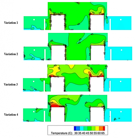
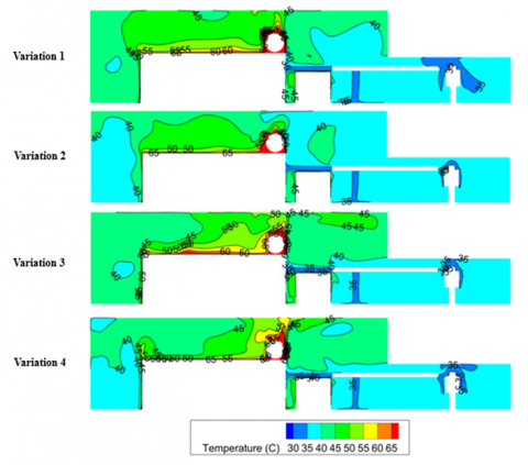
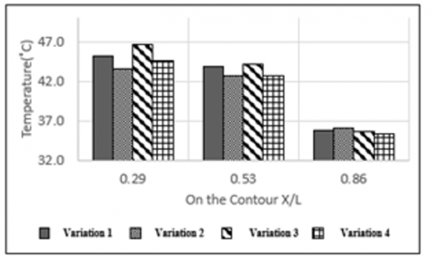
Figure 17 shows the temperature contours along the X/L plane. The temperature profiles show that heat accumulation is more significant at the top of the engine room. At X/L = 0.29, the average temperature reaches 50.9℃ in Variation 3, while Variation 2 decreases to 46.7℃. This result aligns with research that indicates heat tends to build up at higher elevations in enclosed engine rooms, which aligns with the idea that hot air rises due to natural convection [6]. Variations 2 and 4 involving increased blower capacity consistently reduced the average temperature in each X/L plane analyzed. The effectiveness of the blower in removing hot air from critical areas, such as around the fuel separator, is evident from the temperature reduction recorded in these regions. Additionally, the positioning of the blower to direct cool air to specific components proved beneficial in maintaining a lower temperature gradient throughout the room.
Figure 17. Temperature contour on the X/L=0.29 plane
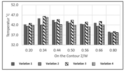
The temperature distribution in the Z/W =11.4m plane, as presented in Figure 18, further supports the notion that increasing blower capacity positively impacts cooling. In the Z/W = 11.4m plane, the initial temperature exceeds 60℃; however, the additional blower capacity in Variation 2 drops to below 45℃. This improvement underscores the importance of optimizing the placement and capacity of blowers to prevent localized overheating, particularly around high-heat-generating equipment. In contrast, adding exhaust fans in Variation 3 increases the average temperature across the Z/W plane. The exhaust system appears to interfere with the overall cooling pattern; as discussed, air extraction can reduce the effect of incoming cold air, resulting in increased thermal loads in some areas [5].
Figure 18. Temperature contour on the Z/W=11.4 m plane
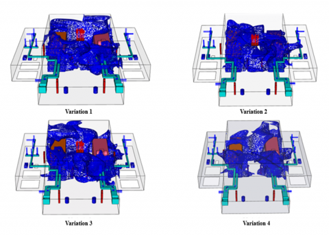
Figures 19 and 20 illustrate ISO temperature distributions in the engine room under four ventilation setups, highlighting heat spread throughout the area as validation. Blue regions depict temperature distribution, which is vital for assessing the thermal environment impacting the six crew members. High-temperature zones can cause discomfort, risk of heat stress, fatigue, and reduced productivity, while prolonged exposure may lead to dehydration and heat-related illnesses, especially in poorly ventilated areas. Thus, effective ventilation that minimizes hot spots and maintains a cooler, even temperature is crucial for crew comfort and safety. These variations guide improvements in ventilation design to protect crew health in extreme temperatures. The results show that increasing the blower capacity (Variations 2 and 4) consistently results in lower temperatures in all areas analyzed. The temperature reduction effect is more pronounced around the ventilation inlet area, indicating that increasing the airflow from the blower provides a more uniform cooling effect. This observation is consistent with findings showing that increasing lateral airflow can effectively control temperature distribution in ship engine rooms [48].
Figure 20 illustrates the X/L plane, revealing that areas at X/L = 0.29 and 0.53, which are located around the main engine, experience elevated temperatures. This finding indicates that the regions closest to the primary machinery are subject to high heat, likely due to the equipment's operational output. On the Y/H plane, it is observed that the highest temperature accumulates at the top of the engine room. This vertical temperature gradient suggests hot air rises, creating a warmer environment near the ceiling. In the Z/W plane, high temperatures are concentrated around and between the primary machines, specifically within the range of Z/W = 0.34 to 0.66. This result is likely because this area is surrounded by heat-emitting equipment, leading to heat buildup between them. However, at Z/W = 0.80, the temperature is comparatively lower, as this side of the engine room is equipped with more inlet ducts, which allow cooler air to enter and reduce the surrounding temperature. This analysis emphasizes the need for strategic placement of ventilation systems, especially in high-temperature zones around and above the primary machines, to ensure optimal cooling and maintain a safer environment within the engine room.
Figure 19. ISO Temperature based on caterpillar standard at 49℃
Figure 20. Temperature comparison of 4 variations
3.4 Brief review as comparison of comport index and heat pressure of engine room
Table 5 shows a brief overview as a comparison of the Engine Room Comfort and Thermal Stress Index from 2020 to 2024. The importance of ventilation in ships' engine rooms is well-documented, particularly concerning its role in ensuring optimal machinery performance, air supply for combustion, and temperature regulation for crew comfort and equipment protection [51]. Effective ventilation maintains the thermal balance needed to avoid overheating and manage exhaust and airflow to facilitate heat dissipation [52]. However, as modern ship designs increasingly prioritize cargo and workspace efficiency over engine room space, ventilation systems face significant challenges in accommodating the compact layout, resulting in complex issues with heat and humidity levels [53].
One critical aspect of ventilation is its impact on both cold and heat stress experienced by crew members. Research highlights that engine rooms on ships represent some of the harshest work environments due to extreme temperatures and fluctuating humidity, which elevate the risk of thermal stress [31]. The design limitations of modern ships exacerbate these thermal extremes, affecting the thermal comfort and health of crew members, who often move between hot engine spaces and cooler regions of the vessel [54]. The research emphasized that crew members will be exposed to potential thermal discomfort hazards without proper ventilation adjustments, thus increasing the need for real-time monitoring of temperature and humidity levels using comfort and heat stress indices [55, 56].
The current findings support the assessment of engine room environments based on established thermal comfort standards, such as those described by ISO. For instance, Altosole et al. [51] argue that ventilation systems must be evaluated for their efficiency in temperature control and impact on mitigating health risks among crew members. Meanwhile, advanced ventilation control strategies can optimize thermal comfort by aligning airflow adjustments with fluctuating temperature and humidity conditions [34]. Additionally, recent computational fluid dynamics (CFD) developments offer promising methods for modeling and improving engine room ventilation systems, enabling precise adjustments to enhance heat dissipation and airflow [8].
Despite these advancements, the literature reveals gaps in standardized guidelines for real-time thermal monitoring in marine environments. For instance, while theoretical models estimate thermal comfort, practical applications often fail to account for the specific conditions encountered in engine rooms, suggesting that further research is needed to refine comfort indices tailored to marine settings [57]. As such, the findings of this study underscore the necessity for industry standards that specifically address ventilation requirements in densely packed engine rooms. Optimizing ventilation in ship engine rooms is paramount to balancing thermal conditions, enhancing crew comfort, and preventing mechanical failures. Future research should focus on developing adaptive ventilation systems that dynamically respond to environmental changes and integrate real-time thermal monitoring to reduce cold and heat stress.
Table 5. Comparison of comfort index and heat pressure
|
No. |
Comport Index of Engine Room |
Heat Pressure |
Ref. |
|
1 |
Influenced by predictive pressure capabilities in engine design |
Relevant for pressure trace prediction for optimal operation |
[58] (2020) |
|
2 |
Affecting thermal management in dual-fuel engine combustion |
Impacts structural deformation and engine safety |
[59] (2020) |
|
3 |
Insights from vehicular thermal comfort extrapolated to marine |
Influences design considerations for managing heat loads |
[60] (2020) |
|
4 |
Critical for fire safety and maintaining operational standards |
Connected to combustion processes and environmental heat loads |
[61] (2020) |
|
5 |
Influenced by temperature and humidity, affecting crew comfort |
Linked to ventilation system effectiveness in confined spaces |
[55] (2021) |
|
6 |
Impacted by ambient and seawater temperature variations |
Directly affects engine performance and efficiency |
[51] (2021) |
|
7 |
Evaluated using the PMV index for crew comfort |
Correlated with thermal management strategies |
[52] (2021) |
|
8 |
Impacted by noise levels affecting stress and comfort |
Complicated by noise pollution impacting overall pressure |
[54] (2021) |
|
9 |
Optimized using integrated comfort and energy models |
Managed through comfort-energy optimization strategies |
[53] (2021) |
|
10 |
Affected by ventilation system design for temperature management |
Critical for fire safety and smoke control |
[56] (2021) |
|
11 |
Impacted by high-temperature exposure affecting crew fatigue and productivity |
Modeled using CFD to understand airflow and temperature hotspots |
[4] (2022) |
|
12 |
Compounded by high noise levels contributing to auditory stress |
Exacerbated by noise and thermal conditions in confined spaces |
[31] (2022) |
|
13 |
Affected by thermal model insight from climate chamber studies |
Evaluated for real-world conditions through climate studies |
[62] (2022) |
|
14 |
Linked to vibration stress impacting comfort and health |
Affected by structural integrity under vibrational loads |
[63] (2022) |
|
15 |
Improved with sound-absorbing materials for noise and vibration reduction |
Mitigated with innovative green composite materials |
[64] (2022) |
|
16 |
Enhanced by machine learning for real-time comfort adjustment |
Managed by an intelligent system for optimal crew comfort |
[65] (2022) |
|
17 |
Optimized by implementing energy management for HVAC systems |
Controlled via energy management strategies in confined spaces |
[34] (2023) |
|
18 |
Influenced by engine room design and ventilation layout |
Dependent on insulation and ventilation effectiveness |
[66] (2023) |
|
19 |
Adapted using adaptive thermal comfort models for fluctuation |
Managed by adaptive controls for responsive temperature changes |
[57] (2023) |
|
20 |
Enhanced with smart materials to regulate interior temperature |
Reduced through advanced insulation and temperature regulation |
[67] (2023) |
|
21 |
Impacted by urbanization effect on external heat stress |
Affected by urban heat exposure in coastal and urban areas |
[68] (2023) |
|
22 |
Improved by automated temperature control systems in ventilation |
Minimized by automated fan systems responding to temperature changes, |
[8] (2024) |
|
23 |
Managed through predictive fire behavior models for safety |
Controlled to reduce fire risk with advanced ventilation strategies |
[50] (2024) |
|
24 |
Optimized using heat dissipation methods to maintain comfort |
Enhanced through holistic CFD simulations for heat dissipation |
[69] (2024) |
|
25 |
Guided by ASHRAE standards for temperature and humidity |
Mitigated by HVAC designs following established comfort standards |
[70] (2024) |
|
26 |
Enhanced by optimized layout of cooling modules for airflow |
Improved cooling module layout influencing air distribution |
[71] (2024) |
|
27 |
Adjusted with AI-based real-time thermal management |
Regulated by machine learning for dynamic temperature control |
[72] (2024) |
|
28 |
Influenced by environmental-friendly carbon capture systems |
Reduced with CCS and SCR systems addressing emissions |
[73] (2024) |
|
29 |
Determination of the distribution of exhaust gas leaks (CO and CO₂) increases with increasing load and engine RPM |
Optimization of ventilation to prevent accumulation of heat and gases harmful to health and engine performance |
Present study |
The current study focuses on the distribution of exhaust gas leaks (CO and CO₂) in the engine room, which increases with higher load and engine RPM. It emphasizes optimizing ventilation to prevent heat accumulation and harmful gases, ensuring health and engine performance. This result aligns with the findings of Alizadeh et al. [7], who investigated the effect of ventilation inlet and outlet arrangements on heat concentration in a ship engine room, and Chen et al. [5], who conducted numerical analyses of ventilation systems using CFD methods. Both studies highlight the importance of proper ventilation design to effectively manage heat and air distribution. While the current research addresses the correlation between exhaust gas leaks and engine load/RPM, the literature broadly focuses on temperature distribution and optimization of ventilation systems. Together, these findings underscore the critical role of ventilation in maintaining optimal conditions in the engine room, as shown in Table 5.
This study reveals the importance of ventilation systems in ship engine rooms in reducing temperatures and maintaining optimal airflow distribution. Using a CFD (Computational Fluid Dynamics) approach, this study identified that exhaust gas leakage (CO and CO₂) increased with increasing engine load, resulting in high heat concentration and potential health hazards for crew members. Key findings indicate that increasing blower capacity and optimal ventilation fan settings significantly reduce heat accumulation, maintain engine room coolness, and improve operational comfort and efficiency.
The implications of this study indicate that adaptive and responsive ventilation system design would be a solution to reduce the risk of heat and gas leakage in ship engine rooms. In addition, using automatic ventilation systems with real-time monitoring is a significant innovation in the maritime industry to ensure energy efficiency and crew safety. The contribution of this study enriches the understanding of engine room ventilation design that prioritizes thermal comfort and risk and safety management. Future stidies should investigate how variations in ventilation design impact vessels of varying sizes and layouts, together with the development of more sophisticated monitoring technologies to support adaptive ventilation systems.
Implementing this study practically involves several challenges, particularly regarding cost and scalability. Upgrading or installing advanced ventilation systems, including high-capacity blowers and optimal ventilation fan settings, requires significant initial capital. This practicality includes equipment cost, installation, and potential retrofitting of existing systems. Additionally, ongoing costs for these systems' maintenance, repairs, and operation can be substantial. Implementing automatic ventilation systems with real-time monitoring involves additional expenses for sensors, control systems, and software, which require continuous updates and technical support.
Scalability presents another set of challenges. The effectiveness of ventilation systems can vary significantly depending on the size and configuration of the ship. Larger ships or those with complex layouts may require more sophisticated and extensive ventilation solutions, which can be challenging to scale. Developing a one-size-fits-all solution is difficult due to the diverse range of ship designs and operational conditions. Integrating new ventilation technologies with existing ship systems can be complex, requiring careful planning and execution to ensure compatibility and seamless operation without disrupting current functionalities. Addressing these challenges requires strategic planning, investment in technology, and a focus on long-term benefits to achieve effective and sustainable solutions.
[1] Nugroho, A., Widodo, W.A., Suryo, I.B. (2024). A review of ventilation systems and fire incidents on ships: A bibliometric and mathematical modelling approach. Mathematical Modelling of Engineering Problems, 11(7): 1961-1972. https://doi.org/10.18280/mmep.110727
[2] Sandle, T. (2020). Review of the efficacy of HEPA filtered air to control coronavirus risks in cleanrooms. European Journal of Parenteral and Pharmaceutical Sciences, 25(2): 1-5. https://doi.org/10.37521/25203
[3] Li, C.F., Zhang, H.Y., Zhang, Y.F., Kang, J.C. (2022). Fire risk assessment of a ship’s power system under the conditions of an engine room fire. Journal of Marine Science and Engineering, 10(11): 1658. https://doi.org/10.3390/jmse10111658
[4] Salmani, A., Hosseini, S.F., Khani, H. (2023). Modelling heat transfer and fluid flow in a ship engine room using CFD analysis to evaluate and improve ventilation. Proceedings of the Institution of Mechanical Engineers, Part M: Journal of Engineering for the Maritime Environment, 237(2): 420-435. https://doi.org/10.1177/14750902221118485
[5] Chen, J.P., Xu, J., Wang, L.T., Chen, X.E., Gong, Y. (2018). Numerical analysis of ventilation for ship E/R with CFD method. International Journal of Performability Engineering, 14(3): 531. https://doi.org/10.23940/ijpe.18.03.p14.531546
[6] Orosa, J.A., Costa, Á.M., Pérez, J.A. (2017). A new modelling procedure of the engine room ventilation system for work risk prevention and energy saving. Proceedings of the Institution of Mechanical Engineers, Part M: Journal of Engineering for the Maritime Environment, 231(4): 863-870. https://doi.org/10.1177/1475090216687148
[7] Alizadeh, E., Maleki, A., Mohamadi, Α. (2017). An investigation of the effect of ventilation inlet and outlet arrangement on heat concentration in a ship engine room. Engineering, Technology & Applied Science Research, 7(5): 1996-2004. https://doi.org/10.48084/etasr.1288
[8] He, P., Luo, W.H. (2024). Improvement of modeling method for engine room ventilation system. In 2023 4th International Conference on Mechanical Engineering, Intelligent Manufacturing and Automation Technology (MEMAT 2023), Guilin, China, pp. 43-50. https://doi.org/10.1117/12.3025929
[9] Wang, K., Ming, Y., Liu, X.L., Wang, H., He, Y.R. (2023). Effect of lateral airflow on initial HSI and flame behavior of marine fuel in a ship engine room: Experiment and analysis. Journal of Marine Science and Engineering, 12(1): 5. https://doi.org/10.3390/jmse12010005
[10] Wu, X.W., Yao, W.B., Jia, J., Chen, X., Lu, S.X. (2024). Large-scale experimental investigation of effect of mechanical ventilation on smoke temperature in ship engine room. Fire Technology, 60: 1287-1311. https://doi.org/10.1007/s10694-022-01331-1
[11] Wu, X.W., Zhang, Y., Jia, J., Chen, X., Yao, W.B., Lu, S.X. (2023). Experimental and theoretical analysis of the smoke layer height in the engine room under the forced air condition. Fire, 6(1): 16. https://doi.org/10.3390/fire6010016
[12] Xie, Y.C., Zheng, Z.P., Wang, H.B., Xu, Z., Liu, G.J., Malekian, R., Li, Z.X. (2019). Analysis of a main cabin ventilation system in a jack-up offshore platform Part I: Numerical modelling. Applied Sciences, 9(15): 3185. https://doi.org/10.3390/app9153185
[13] Barsocchi, P., Ferro, E., La Rosa, D., Mahroo, A., Spoladore, D. (2019). E-Cabin: A software architecture for passenger comfort and cruise ship management. Sensors, 19(22): 4978. https://doi.org/10.3390/s19224978
[14] Sim, H., Ha, W.J., Park, Y.S. (2019). A basic study on standardization of fire-fighting drill scenarios on board. Journal of International Maritime Safety, Environmental Affairs, and Shipping, 3(3-4): 28-35. https://doi.org/10.1080/25725084.2019.1698897
[15] Mansi, F., Cannone, E.S.S., Caputi, A., De Maria, L., Lella, L., Cavone, D., Vimercati, L. (2019). Occupational exposure on board fishing vessels: Risk assessments of biomechanical overload, noise and vibrations among worker on fishing vessels in southern Italy. Environments, 6(12): 127. https://doi.org/10.3390/environments6120127
[16] Li, Y.G., Qian, H., Hang, J., Chen, X.G., et al. (2020). Evidence for probable aerosol transmission of SARS-CoV-2 in a poorly ventilated restaurant. MedRxiv. https://doi.org/10.1101/2020.04.16.20067728
[17] Correia, G., Rodrigues, L., Da Silva, M.G., Gonçalves, T. (2020). Airborne route and bad use of ventilation systems as non-negligible factors in SARS-CoV-2 transmission. Medical Hypotheses, 141: 109781. https://doi.org/10.1016/j.mehy.2020.109781
[18] Nembhard, M.D., Burton, D.J., Cohen, J.M. (2020). Ventilation use in nonmedical settings during COVID-19: Cleaning protocol, maintenance, and recommendations. Toxicology and Industrial Health, 36(9): 644-653. https://doi.org/10.1177/0748233720967528
[19] Morawska, L., Tang, J.W., Bahnfleth, W., Bluyssen, P.M., et al. (2020). How can airborne transmission of COVID-19 indoors be minimised? Environment International, 142: 105832. https://doi.org/10.1016/j.envint.2020.105832
[20] Dewi, C.P. (2020). Optimization of natural ventilation in building as passive design strategy for health security. Proceeding International Conference on Engineering, 1(1): 25-31.
[21] Pearce, J.M. (2020). A review of open source ventilators for COVID-19 and future pandemics. F1000Research, 9: 218. https://doi.org/10.12688/f1000research.22942.2
[22] Kordsmeyer, A.C., Mojtahedzadeh, N., Heidrich, J., Militzer, K., et al. (2021). Systematic review on outbreaks of SARS-CoV-2 on cruise, navy and cargo ships. International Journal of Environmental Research and Public Health, 18(10): 5195. https://doi.org/10.3390/ijerph18105195
[23] Almilaji, O. (2021). Air recirculation role in the spread of COVID-19 onboard the diamond princess cruise ship during a quarantine period. Aerosol and Air Quality Research, 21(4): 200495. https://doi.org/10.4209/aaqr.200495
[24] Cotman, Z.J., Bowden, M.J., Richter, B.P., Phelps, J.H., Dibble, C.J. (2021). Factors affecting aerosol SARS-CoV-2 transmission via HVAC systems; A modeling study. PLOS Computational Biology, 17(10): e1009474. https://doi.org/10.1371/journal.pcbi.1009474
[25] Afshari, A., Hultmark, G., Nielsen, P.V., Maccarini, A. (2021). Ventilation system design and the coronavirus (COVID-19). Frontiers in Built Environment, 7: 662489. https://doi.org/10.3389/fbuil.2021.662489
[26] Nardell, E.A. (2021). Air disinfection for airborne infection control with a focus on COVID-19: Why germicidal UV is essential. Photochemistry and Photobiology, 97(3): 493-497. https://doi.org/10.1111/php.13421
[27] Ba, Z.F., Zhang, Z.J., Zong, Y.G. (2021). Design and research on intelligent ventilation system of ship cargo hold. Journal of Physics: Conference Series, 2131(3): 032120. https://doi.org/10.1088/1742-6596/2131/3/032120
[28] Nguyen, T.D., Bui, H.M. (2023). Computational fluid dynamic model for smoke control of building basement. Case Studies in Chemical and Environmental Engineering, 7: 100318. https://doi.org/10.1016/j.cscee.2023.100318
[29] Noh, S.J., Park, M., Chin, S.W., Choi, C., Ha, M.Y. (2022). Application of virtual product design to the development of HVAC solution for Incheon International Airport Modular COVID-19 testing center. Case Studies in Chemical and Environmental Engineering, 6: 100257. https://doi.org/10.1016/j.cscee.2022.100257
[30] Yang, N., Deng, X.W., Liu, B., Li, L.W., Li, Y., Li, P., Tang, M., Wu, L. (2022). Combustion performance and emission characteristics of marine engine burning with different biodiesel. Energies, 15(14): 5177. https://doi.org/10.3390/en15145177
[31] Layuk, S., Martiana, T., Alow, G.B.H., Katiandagho, D., Pomalango, C., Afiyah, R.K., Hasina, S.N. (2022). Physical environment and work fatigue among ship engine room crew. International Journal of Health Sciences, 6(3): 1556-1564. https://doi.org/10.53730/ijhs.v6n3.13248
[32] Lan, Q.Y., Han, F.H., Liu, Y.X., Li, W.H., Wang, Z. (2023). Effects of ventilation system design on flame behavior and smoke characteristics for mitigating marine engine room fire hazards. Ocean Engineering, 281: 114890. https://doi.org/10.1016/j.oceaneng.2023.114890
[33] Schalm, O., Carro, G., Jacobs, W., Lazarov, B., Stranger, M. (2023). The inherent instability of environmental parameters governing indoor air quality on board ships and the use of temporal trends to identify pollution sources. Indoor Air, 2023(1): 7940661. https://doi.org/10.1155/2023/7940661
[34] Liu, C.Y., Su, Y.X., Zhang, D.H. (2023). Optimal control strategy for ship cabin’s active chilled beam system using improved multi-objective salp swarm algorithm. Journal of Marine Science and Engineering, 11(7): 1396. https://doi.org/10.3390/jmse11071396
[35] Liu, S., Li, X.C., Li, J., Shu, L., Fu, T.M., Yang, X., Zhu, L. (2023). Observing network effect of shipping emissions from space: A natural experiment in the world’s busiest port. PNAS Nexus, 2(11): pgad391. https://doi.org/10.1093/pnasnexus/pgad391
[36] Ergin, S., Mocerino, L., Quaranta, F. (2022). Possible approaches to the study of the emissions from ships during their operations in ports. Proceedings of the Institution of Mechanical Engineers, Part M: Journal of Engineering for the Maritime Environment, 238(2): 273-280. https://doi.org/10.1177/14750902231210564
[37] Gao, Q.X., Sun, Q., Zhang, P., Zhao, G., Peng, W. (2024). Research on active and passive schemes for safety improvement of nuclear energy hydrogen production system. Frontiers in Nuclear Engineering, 3: 1381737. https://doi.org/10.3389/fnuen.2024.1381737
[38] Paulson, M., Babu, S., Chacko, M. (2024). Leveraging an installed standalone photovoltaic system for eco-friendly shipping. Engineering Review, 44(1): 83-98. https://doi.org/10.30765/er.2318
[39] Bruno, R., Ferraro, V., Barone, P., Bevilacqua, P. (2024). Energy and exergy analyses of an innovative heat recovery system from the LNG regasification process in green ships. Clean Technologies, 6(3): 826-851. https://doi.org/10.3390/cleantechnol6030043
[40] Mihai, V., Rusu, L. (2021). An overview of the ship ventilation systems and measures to avoid the spread of diseases. Inventions, 6(3): 55. https://doi.org/10.3390/inventions6030055
[41] Cao, Y.H., Wang, X.J., Yang, Z.L., Wang, J., Wang, H.X., Liu, Z.J. (2023). Research in marine accidents: A bibliometric analysis, systematic review and future directions. Ocean Engineering, 284: 115048. https://doi.org/10.1016/j.oceaneng.2023.115048
[42] Febriyanto, K., Guedes, J.C.C., Mourão, L.J.R.D.N.C. (2024). A scoping review on occupational noise mitigation strategies and recommendations for sustainable ship operations. International Journal of Environmental Research and Public Health, 21(7): 894. https://doi.org/10.3390/ijerph21070894
[43] Duong, P.A., Ryu, B.R., Jung, J., Kang, H. (2024). A comprehensive review of the establishment of safety zones and quantitative risk analysis during ship-to-ship LNG bunkering. Energies, 17(2): 512. https://doi.org/10.3390/en17020512
[44] Deniz, C., Kilic, A., Cıvkaroglu, G. (2010). Estimation of shipping emissions in Candarli Gulf, Turkey. Environmental Monitoring and Assessment, 171: 219-228. https://doi.org/10.1007/s10661-009-1273-2
[45] Tawfiq, A., Mansour, M., El-Taybany, A. (2017). Assessment of the emissions from seagoing ships in Suez Canal. Port-Said Engineering Research Journal, 21(2): 128-137. https://doi.org/10.21608/pserj.2017.33301
[46] Zhang, Z.D., Wang, H.J., Cao, K., Li, Y. (2023). Using a convolutional neural network and mid-infrared spectral images to predict the carbon dioxide content of ship exhaust. Remote Sensing, 15(11): 2721. https://doi.org/10.3390/rs15112721
[47] Chen, Y., Pan, S.D. (2024). Exhaust emission monitoring system based on the Internet of Things for ships passing through waterway lock. In Third International Conference on Electronic Information Engineering, Big Data, and Computer Technology (EIBDCT 2024), Beijing, China, pp. 1128-1133. https://doi.org/10.1117/12.3031101
[48] Zhao, Y.C., Zhao, H.B., Miao, Z.Y., Ai, D.H., Wang, Q.F. (2023). A numerical study on the smoke dispersion and temperature distribution of a ship engine room fire based on OpenFOAM. Sustainability, 15(20): 15093. https://doi.org/10.3390/su152015093
[49] Wu, X.W., Yao, W.B., Jia, J., Chen, X., Lu, S.X. (2024). Large-scale experimental investigation of effect of mechanical ventilation on smoke temperature in ship engine room. Fire Technology, 60(2): 1287-1311. https://doi.org/10.1007/s10694-022-01331-1
[50] Wang, K., Qiu, R., Ming, Y., Xu, H. (2024). Experimental study on the hot surface ignition characteristics and a predictive model of marine diesel in a ship engine room. Journal of Marine Science and Engineering, 12(5): 798. https://doi.org/10.3390/jmse12050798
[51] Altosole, M., Balsamo, F., Mocerino, L., Quaranta, F., Campora, U., Rizzuto, E. (2021). Analysis of ship performance data for the evaluation of marine engines emissions in ports. In Maritime Technology and Engineering, 5 Volume 2, CRC Press, pp. 449-456. https://doi.org/10.1201/9781003216599-47
[52] Chen, X.Y., Bu, L., Chen, C., Gan, L., Yu, K. (2021). An operational optimization method of regional multi-energy system considering thermal quasi-dynamic characteristics. CSEE Journal of Power and Energy Systems, 10(6): 2551-2563. https://doi.org/10.17775/cseejpes.2020.03830
[53] Cai, W., Liu, W.S., Wan, S.Q., Zeng, Q.S. (2021). Evaluation study on integration of comfort and energy efficiency models in cruise ship. International Conference on Offshore Mechanics and Arctic Engineering, 85161: V006T06A036. https://doi.org/10.1115/OMAE2021-62512
[54] Jégaden, D. (2021). Concerning the relationship between noise on board ship and the onset of hypertension in seafarers. Archives of Preventive Medicine, 6: 001-002. https://doi.org/10.17352/apm.000026
[55] Niu, A.Q., Guo, M.X., Wang, J.L., Chen, M.Q., Jin, G.L., Wang, S.H. (2021). Numerical simulation of thermal environment in 320,000 tons VLCC engine room. IOP Conference Series: Earth and Environmental Science, 687(1): 012106. https://doi.org/10.1088/1755-1315/687/1/012106
[56] Wu, Z.Z., Wang, L., Su, S.C., Liu, W. (2022). Experimental and simulation study of the interaction characteristics of nano-MgO and smoke in the fire of a ship engine room. Fire and Materials, 46(7): 953-967. https://doi.org/10.1002/fam.3043
[57] Lamsal, P., Bajracharya, S.B.,Rijal, H.B. (2023). Adaptive thermal comfort for energy saving office building design-A literature review. E3S Web of Conferences, 396: 01083. https://doi.org/10.1051/e3sconf/202339601083
[58] Shen, H.S., Zhang, J.D., Yang, B.C., Jia, B.Z. (2020). Development of a marine two-stroke diesel engine MVEM with in-cylinder pressure trace predictive capability and a novel compressor model. Journal of Marine Science and Engineering, 8(3): 204. https://doi.org/10.3390/jmse8030204
[59] Liu, D., Sun, B., Song, J.W., Wang, T.P., Ma, X.Y. (2020). Effects of thermal and pressure loads on structural deformation of liquid oxygen/methane engine combustion chamber. Journal of Thermal Science and Technology, 15(3): JTST0022. https://doi.org/10.1299/jtst.2020jtst0022
[60] Khatoon, S., Kim, M.H. (2020). Thermal comfort in the passenger compartment using a 3-D numerical analysis and comparison with Fanger’s comfort models. Energies, 13(3): 690. https://doi.org/10.3390/en13030690
[61] Tutak, W., Grab-Rogaliński, K., Jamrozik, A. (2020). Combustion and emission characteristics of a biodiesel-hydrogen dual-fuel engine. Applied Sciences, 10(3): 1082. https://doi.org/10.3390/app10031082
[62] Jusoh, N., Ismail, A.R., Zein, R.M. (2022). Human responses to the thermal comfort in air-conditioned building: A climate chamber study. International Journal of Integrated Engineering, 14(1): 287-295. https://doi.org/10.30880/ijie.2022.14.01.027
[63] Alamsyah, A., Kala, C.S., Wulandari, A.I. (2022). The analysis of engine room vibration of tugboat 24 M. Maritime Park: Journal of Maritime Technology and Society, 93-101. https://doi.org/10.62012/mp.v1i3.23608
[64] Manik, P., Tuswan, T., Musarofah, S., Chrismianto, D., Samuel, S., Prabowo, A.R. (2022). The development of sound absorber material from green composites: The effect of volume fraction on noise reduction and thermal conductivity performances for ship engine room application. Pomorstvo, 36(2): 223-233. https://doi.org/10.31217/p.36.2.6
[65] Zeng, J., Jin, B.W., Zhang, H., Mai, S.Y., Yuan, B., Jiang, H., Yang, M.K., Huang, C.C. (2022). The mathematical model of marine engine room equipment based on machine learning. Wireless Communications and Mobile Computing, 2022(1): 8366670. https://doi.org/10.1155/2022/8366670
[66] Acar, A., Uryan, M., Doğrul, A., Karakurt, A.S., Çelik, C. (2023). Numerical investigation of HVAC systems of a naval ship compartment: Natural ventilation and air-conditioning. Journal of Naval Sciences and Engineering, 19(1): 77-100. https://doi.org/10.56850/jnse.1274350
[67] Peri, A.D. (2023). Smart materials finishing and insulation solutions applied to the interior design of a cruise ship cabin. Seatific Journal, 3(2): 89-110. https://doi.org/10.14744/seatific.2023.0010
[68] Li, W., Chao, L.Y., Si, P., Zhang, H.X., Li, Q.X. (2023). Comparisons of the urbanization effect on heat stress changes in Guangdong during different periods. Remote Sensing, 15(11): 2750. https://doi.org/10.3390/rs15112750
[69] Liu, C.B., Liang, S.J., Yang, G.Y. (2024). Optimization of heat dissipation performance of engine compartment based on SSA-RBFNN-NSGA-II. In Fourth International Conference on Mechanical Engineering, Intelligent Manufacturing, and Automation Technology (MEMAT 2023), Guilin, China, pp. 726-732. https://doi.org/10.1117/12.3026343
[70] Fattahi, A., Sharaf, H.K., Mariah, N. (2024). Thermal comfort assessment of UPM engineering library in tropical climate conditions. Journal of Advanced Research in Applied Mechanics, 117(1): 179-189. https://doi.org/10.37934/aram.117.1.179189
[71] Gao, Z.H., Yang, Y., Zhang, Y.J., Li, M. (2024). Research on the influence of cooling module layout on flow and heat transfer performance in commercial vehicles. Research Square. https://doi.org/10.21203/rs.3.rs-4244604/v1
[72] Ma, R.N., Cao, H., Song, Z.H., Wu, X.Y. (2024). Study on Chinese semantic entity recognition method for cabin utilizing BERT-BiGRU model. IEEE Access, 12: 56042-56049. https://doi.org/10.1109/ACCESS.2024.3386760
[73] Zincir, B.A., Zincir, B., Deniz, C., Usluer, H.B., Arslanoglu, Y. (2024). Environmental impact investigation of combined CCS and SCR on a ship by a case study. Greenhouse Gases: Science and Technology, 14(4): 607-619. https://doi.org/10.1002/ghg.2291