Rafah H. Zaidan*![]() | Najim A. Jasim
| Najim A. Jasim![]()
© 2025 The authors. This article is published by IIETA and is licensed under the CC BY 4.0 license (http://creativecommons.org/licenses/by/4.0/).
OPEN ACCESS
The installation of radiant heating flooring is a prevalent approach to generating toasty, comfortable heat within a structure. In this paper's numerical study, two distinct radiant floor heating schemes are contrasted, each of which accounts for varying inlet hot water temperatures and flow rates. The thermal performance and energy efficiency of two radiant heating floor designs, the spiral and the serpentine—were evaluated in this study under a variety of conditions. These conditions included hot water temperatures of 50 and 60℃ with a step of 5℃ and flow rates of 3 and 12 Lit/min with a step of 3 L/min. Numerical simulations were implemented to evaluate parameters such as thermal comfort, energy efficiency, and heat dispersion homogeneity. The models were developed using SolidWorks software, and numerical simulations were conducted using ANSYS-Fluent 21 software. The ANSYS software calculations revealed that the design variations were nearly identical. This paper takes a case study at 12 Lit/min. The spiral model exhibits a higher uniformity in the temperature distribution on the tile's surface than the serpentine model when the input water temperature reaches 55℃. The average difference between the two models is approximately 0.5%. The distribution temperature within the slab was found to be slightly higher in the serpentine model than the spiral model, with a difference of 0.66%. These findings indicate that the serpentine design exhibits superior thermal homogeneity and heat distribution with 15.05% enhancing percentage in heat gain at 55℃ inlet temperature for the serpentine more than the spiral layout. The numerical and published work findings were in satisfactory agreement, and these findings contribute to the enhancement of radiant floor heating systems to enhance their energy efficiency and user comfort. Additionally, the disparity between the two configurations decreased by approximately 4.1, 3.7, and 1.7% as the inlet temperature increased from 50℃ to step by 5℃.
radiant heating floor, spiral pipe, serpentine pipe, energy analysis, numerical analysis
Radiant floor heating (RFH) systems are popular for energy-efficient, comfortable heating in residential and commercial buildings. They heat spaces directly by warming the floor, allowing even distribution. Common designs include electric and hydronic systems.
The thermal performance of an underfloor heating system was analyzed using CFD simulations for different pipe patterns. Results showed that the spiral configuration offers the most uniform floor temperature and results in lower pressure losses compared to counterflow and modulated serpentine designs [1].
The study explores the use of recycled steel powder in concrete to enhance the thermal properties of radiant floor heating systems, revealing a 26% decrease in compressive strength and a 3% slower heat transfer rate during heating [2].
Olesen [3] studied three types of radiant floor heating: Electric radiant floors, utilizing air as the heat transfer medium (radiant air floors), and hot water radiant floors. These groups can be further explained by installation methods. Wet installations that the considerable thermal mass of a cement slab floor or lightweight cement above a wooden subfloor were termed but dry fixings are those in which the radiant floor tubing is sandwiched between two layers of plywood or affixed beneath the finished floor or subfloor.
The study of Werner-Juszczuk [4] analyzes the operative factors of a radiant ground heating system as a cooling system. The parameters be based on pipe space, Thermal resistivity of Surface covering, air temperature in the cooled space and water temperature. The only parameter that can be adjusted for system performance is water temperature. The ideational cooling efficiency of a radiant floor is reduced by the lowest surface temperature, which depends on air humidity and thermal comfort requirements set by standard 11855.
A ground-source heat pump system (GSHP) using a ground heat exchanger (GHE) has been identified as an environmentally sustainable alternative for cooling and heating housing and commercial buildings [5]. A new U-tube pipe shape improved thermal transfer efficiency, resulting in a 76.3% differential improvement and superior heat transfer efficiency.
A thermal optimization procedure was implemented to enhance the heating performance of the original wood panel prototypes [6]. The information obtained sets were included into a calibrated numerical model that considered anisotropic material features. An improved panel variation had an average surface temperature of 3.4℃ greater than that of the first prototype.
The study of Kong et al. [7] presents a unique heating method called low temperature radiant floor combined with intermittent subsurface ventilation (LTR-ISV). The research found that heating demand in investigative rooms increased significantly due to inadequate thermal insulation. The LTR-ISV system examined the heat supply relationship between stratum ventilation and radiant floor heating. The study also analyzed the TRNSYS simulation model of workplaces using radiant ceiling panels for heating and cooling. Human activities only impacted annual energy consumption to a limited extent.
A study on three panels beside a hydronic radiant floor system tested different mortar formulas [8]. Results showed a temperature variance exceeding 3℃. The intermittent heating configuration reduced operational hours by 49.3% with the improved screed mortar M_01, while M_02 reduced operational hours by 40.2%. Monthly analysis showed a significant decrease in operation time for both types. The temperature surface disparity among cork and ceramic finishing materials was also noted.
A study on the apply of phase change materials (PCMs) in radiant heating and cooling systems found that the use of PVC radiant flooring significantly reduced greatest heat flow 10-18% and enhanced thermal energy storage by 243% [9]. The system was most effective in wet and hot environments with a 6-mm phase change material thickness and nocturnal ventilation. A 10-mm PCM resulted in a 2.4% yearly decrease in heating energy consumption. A 20-50-mm PCM can result in annual heating energy savings varying from 7.3% to 15.3%. N-eicosane demonstrated the highest efficacy as PCM for floor heating, resulting in a 43% decrease in energy depletion. Radiant floor systems can achieve energy savings of about 4% for heating and 8% for cooling.
A thermal system combining radiant floor heating and adaptive heating convention was presented, evaluating comfort and energy consumption [10]. The study found that Mode 1, which relies solely on convection, is unsuitable for tenants sleeping on the ground. Kinds 2, 3, and 4 show elevated floor temperatures once warm water is delivered to the radiant heating panel. The study also found that Mode 1, along with Modes 3 and 4, provides a more comfortable environment.
A study aimed to find the optimal pipe configuration for heating benches in steam baths, focusing on temperature distribution for client comfort [11]. The design included insulation on the lower side to channel heat upwards. The thermic performance of the underfloor thermal system was evaluated by employing CFD software "COMSOL Multiphysics" and a new parameter to quantify floor thermal uniformity. The modified spiral structure was found to be the most effective solution, reducing pressure losses and achieving optimal temperature uniformity.
Hooshmand et al. [12] explored the use of local radiant heating systems for thermal comfort at lower air temperatures. These systems directly heat the body, reducing energy use and providing equivalent thermal sensation at lower temperatures. The study highlights the need for improved local thermal comfort and sensation modelling, based on radiant heat transmission. The research also highlights the evolving nature of heating technology to improve the thermal environment in occupied zones. The results suggest that localized radiant heating systems can achieve optimal thermal comfort and reduce energy consumption, demonstrating the potential of radiant local systems in achieving thermal comfort.
A radiant floor cooling system using phase change materials and thermal energy storage is proposed to reduce peak demand [13]. Five tests were conducted during warm and dry seasons, revealing that the counter design was more energy-efficient, saving 6% compared to the spiral design. The optimal water mass flow rate was 0.5 kg/s, but the system's performance did not significantly improve. The numerical results strongly correlated with experimental findings, particularly regarding PCM behavior, temperature distribution, thermal power, and Nusselt number (NU).
The analysis of historical and contemporary data reveals that radiant, water-based systems outperform convective, air-based thermal conditioning, and passive techniques can reduce energy demand [14]. Future thermal systems must have onsite thermal energy storage for renewable energy or passive techniques. The literature identified theoretical deficiencies in control strategies, suggesting energy savings and systemic solutions.
An experimental radiant floor heating system was built using phase-change heat storage materials, incorporating sodium silicate, aluminum oxide, and expanded graphite [15]. The system was tested under various ambient temperature conditions, with the optimal water supply temperature being 40℃. Results showed that the natural heat release time for control group A ranged from 0.5 hours to 5.3 hours, while experimental group B had a duration between 6.5 hours and 10.5 hours. The PCM heat storing material's heat discharge duration ranged from 5 to 6 hours. The study concluded that phase-change heat storage materials effectively supplied heat for indoor heating, mitigated indoor temperature decline, enhanced energy utilization efficiency, and facilitated temporal energy displacement.
Gür et al. [16] explored the sketch and performance of a solar- supported home radiator for nearly zero-energy buildings (nZEBs). The system uses a Photovoltaic/Thermal collector and Nano-improved Phase Change Materials (NIPCM) with Boron Carbide (B4C) nanoparticles to improve efficiency. The introduction of nano-B4C-enhanced PCM offers a sustainable and efficient alternate heating, addressing traditional limitations and promoting low-energy, self- behind building environments.
Cui et al. [17] discussed the improvement status of radiant floor cooling systems (RFCS) and their potential applications. It highlights the importance of self-regulating capabilities in addressing cooling demand and grid stability. The review also discusses the challenges of anti-condensation and system design, and the integration of RFCS with ventilation systems. It also highlights the need for proper sizing to maintain cooling performance. The review also highlights the need for research on passive condensation methods and the application and retrofitting of RFCS. Radiant floor systems contribute significantly to energy conservation and emission reduction, making them a valuable tool for clean energy utilization.
The integration of renewable heating and cooling (RHC), photovoltaics, heat pumps, and district heating can reduce primary energy use by 40% to 80% [18]. Thermally activated building systems (TABS) can provide load shifting upwards to 100%, hence enhancing the internal consumption of renewable energy. This research presents evidence about the efficacy of integrating radiant systems with renewable energy sources as a viable technique for attaining almost negative yearly energy balances in building inventories.
Through the assessment of earlier research that improves radiant heating floors, especially those that use hydronic work fluid, it has been identified that a gap remains in achieving optimal performance for these systems. This study focuses on the performance of radiant floor heating systems including the design of the heating pipe layout and the inlet temperature of the circulating water. Therefore, comparing two common designs spiral and serpentine numerically under varying inlet temperatures to determine their impact on energy efficiency and heat distribution. By analyzing these variables and seeking to provide actionable insights for optimizing radiant heating floor designs.
The heated floor systems, with pipes embedded, encompasses the whole area of the two living rooms, with each room exhibiting a distinct pipe configuration.
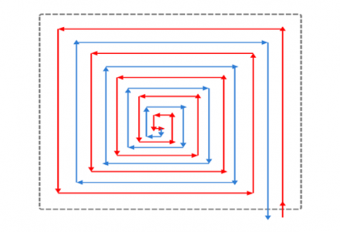
Figures 1 and 2 illustrate it schematically. This article examines a comparable analysis of an under-floor heating technique based on the pipe layout kind, namely double serpentine versus spiral. The heating characteristics of looped pipes can substantially influence the effectiveness of heating systems in occupied spaces. Consequently, we analyze and contrast two frequently utilized piping substances for heating floor coils, specifically cross-linked polyethylene (PEX) and copper [18]. The choice of PEX coils for this study was influenced by durability considerations. The flooring assembly has five strata: A ceramic floor layer, a cement cover, a grid of heating conduits, insulation, and a slab. The concrete layer incorporates the network of PEX pipes. That substantial stays the most prevalent in this way applications. This system functions at outlet temperatures from the energy source of around 60℃. The cement slab retains heat & radiates it into the rooms with the heated water underfloor heating structure, obeying the NF DTU 65.14 P1 guideline [11]. The temperature of radiant heating floors often attains 22℃, with levels of humidity fluctuating between 30% and 50%, rendering the heat tolerable for comfort. Thermal emissions arise from convection via the heating tiles. The calculations are determined by space’s specifications and rely on various factors, with the distance in the middle of the tubes, the thermic resistance of the covering, and the type of isolation. The variable is inlet water temperatures: 50℃, 55℃, and 60℃ as well as changing the flow rate of hot water 3,6,9,12 L/min.
Figure 1. Schematic diagram for spiral layout
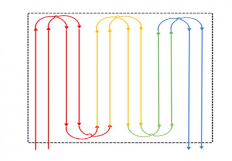
Figure 2. Schematic diagram for serpentine layout
2.1 Assumptions and equations
The thermic characteristics of the technique panel are:
Considering the earlier assumptions, the heat transfer equations for this structure in a 3D configuration and under steady-state conditions are represented by the continuity-equation. The equation of conservation energy is spilites using the 1st-order windy scheme, while the conservation of momentum equation is discretized using the second order upwind scheme.
Continuity equation can be illustrated by [20]:
$\frac{\partial \rho}{\partial t}+\nabla \cdot(\rho v)=0$ (1)
where, V, ρ, and t are the velocity, local density, and time, respectively.
Energy equation is provided in Eq. (2) [21]:
$\begin{aligned}
\frac{\partial}{\partial t}(\rho E)+\frac{\partial}{\partial X_i}[ & \left.u_i(\rho E+P)\right] \\
& \left.=\frac{\partial}{\partial X_j}\left[K_{e f f} \frac{\partial T}{\partial X_j}+u_i\left(\tau_{i j}\right)_{e f f}\right)\right] \\
& +S_h
\end{aligned}$ (2)
where, $P$: static pressure, $\left(\tau_{i j}\right)_{\text {eff }}$. stress tensor, $S_h$, is the expressed the supplier term provided by equation:
$S_h=\frac{-U_g X A X\left(T_s-T_a\right)}{V_r}$ (3)
E is overall energy symbolized by:
$E=h-\frac{P}{\rho}+\frac{u_i^2}{2}$ (4)
The stress tensor $\left(\tau_{i j}\right)_{\text {eff }}$ is presented by the subsequent relationship giving:
$(\tau i j)_{e f f}=\mu_{e f f}\left\lceil\frac{\partial u_i}{\partial x_i}+\frac{\partial u_j}{\partial x_j}\right\rceil-\frac{2}{3} \delta_{i j} \mu_{e f f} \frac{\partial u_k}{\partial x_k}$ (5)
where, I: unit tensor, μ: molecular viscosity, and next term in the right hand is the cause by volume increase.
Differential balance explaining momentum conservation for a Newtonian flow is:
$
\frac{\partial u}{\partial t}+u_i \frac{\partial u_i}{\partial x_i}=-\frac{1}{\rho} \frac{\partial P}{\partial x_i}+\frac{\partial}{\partial x_j}\left(\mu \frac{\partial u_i}{\partial x_j}\right)
$ (6)
To resolve a governing-equation mathematically, the turbulence enclosure model applied here is the model K-ɛ to analyze the turbulent proprieties of flow. This kind is presented by Oubenmoh et al. [22] and provides a general explanation of turbulence using 2 transport relations.
The equation for “turbulence kinetic energy”, K, is represented as follows (7) [23]:
$
\begin{aligned}
\frac{\partial}{\partial t}(\rho k)+\frac{\partial}{\partial x_i}(\rho & \left.k u_i\right) =\frac{\partial}{\partial x_j}\left[\left(\mu+\frac{\mu_t}{\sigma_k}\right) \frac{\partial k}{\partial x_j}\right]+G_k+G_b
-\rho_{\varepsilon}-Y_m+S_k
\end{aligned}
$ (7)
Equation of the specific dissipation rate of turbulent energy ɛ is represented by Eq. (8) [24]:
$\begin{aligned} \frac{\partial}{\partial t}(\rho \varepsilon)+\frac{\partial}{\partial x_i}\left(\rho \varepsilon u_i\right) =\frac{\partial}{\partial x_j}\left[\left(\mu+\frac{\mu_t}{\sigma_k}\right) \frac{\partial \varepsilon}{\partial x_j}\right]+G_{1 \varepsilon} \frac{\varepsilon}{k}\left(G_k\right. & \left.-G_{3 \varepsilon} G_b\right)-G_{2 \varepsilon \rho} \frac{\varepsilon^2}{k}+S_{\varepsilon}\end{aligned}$ (8)
“Gk, Gb, Ym in Eq. (7) the generation of turbulence kinetic energy due to mean velocity gradients, buoyancy, and fluctuating dilatation in compressible turbulence contribute to the overall dissipation rate. Additionally, G1ε, G2ε, and G3ε are constants. The coefficients σk and σε are the turbulent Prandtl numbers for k and ɛ, respectively. Sk and Sɛ are user-defined source terms”. The model constants are provided in Table 1.
Table 1. Coefficients values of the k-ε type
|
$C_u$ |
$\mathrm{C}_{1 \varepsilon}$ |
$\mathrm{C}_{2 \varepsilon}$ |
$\mathrm{C}_{3 \varepsilon}$ |
$\sigma_{\mathrm{k}}$ |
$\sigma_{\varepsilon}$ |
|
0.09 |
1.44 |
1.92 |
1 |
1 |
1.3 |
The ground's cover temperature average is determined using Eq. (9):
$T_s=\frac{1}{S} \int_0^s T_{i o} d x$ (9)
The heat transfer coefficient hw for the surface between water and pipe was calculated from:
$\mathrm{h}_{\mathrm{w}}=0.116\left(\mathrm{Re}^{2 / 3}-125\right) \mathrm{Pr}^{1 / 3}\left(1+(\mathrm{di} / \mathrm{L})^{2 / 3}\right) \mathrm{kp} / \mathrm{di}$ (10)
where, L is the characteristic length (m) of the pipe, kp thermal conductivity of the pipe (W/m.K), di inner diameter of the pipe (m), Re Reynolds number (-), Pr Prandtl number (-).
The heat add or loss was calculated by equation form:
$q=m \cdot c p \Delta T$ (11)
2.2 Mesh report
Unregulated Polyhedral mesh is specified in the investigation for the solid area where pipes are installed. Density of mesh can change the correctness of numerical computations. As a result, in the imitation process, the information was found in Table 2.
Table 2. Mesh data
|
Domain |
Nodes |
Elements |
|
air |
17362254 |
3330485 |
|
c |
205214 |
40800 |
|
conc |
5052913 |
1835314 |
|
pipe |
1795546 |
1449580 |
|
slab |
242807 |
80400 |
|
wood |
81204 |
40200 |
|
All Domains |
24739938 |
6776779 |
The suggested study is to model several configurations of serpentine loops to find the one that validates a consistent surface temperature. Figures 1 and 2 depict the 2 kinds of coil models employed for underfloor-heating: spiral and serpentine layouts. The selected coil configuration is a four-sided floor with dimensions of (2*2) meters in length & width respectively. The spiral structure (Figure 1) comprises a tube approximately 54 meters in length. The distance between the two tube designs is 16 cm. The serpentine configuration (Figure 2) comprised an approximately 34-meter arrangement, maintaining identical spacing to enable a comparison between the two settings. At time t=0, the initial ground temperature is Ts=17℃, and the heat transfer fluid utilized in the study is water, classified as a non-compressible fluid. Table 3 presented the input parameters of computational model while Table 4 presents a comprehensive analysis of the enter components heating pipes, heat transfer fluid, and the floor is used for ambient exchange in the computation for modelling the heating system within the rooms. We consider the bounds of our field in an adiabatic manner.
Table 3. Input parameters for computational modeling
|
Fluid (Water) |
Piping (PEX) [19] |
Floor (Concrete) |
|
Density: r=1000 Kg/m |
|
Density: ρs=2300 Kg/m3 |
|
Thermal conductivity: K=1.6 W/m. K |
Thermal conductivity: Kc= 0.41 W/m. K |
Thermal conductivity: Ks=1.75 W/m. K |
|
Heat capacity: Cp=4185 J/K. Kg |
|
Heat capacity: Cp=878 J/K. Kg |
Table 4. Characteristics of PEX pipe [25]
|
Parameter |
Value |
|
Conductivity of pipe wall |
0.45 kJ/h.m.k |
|
Spacing between Pipes |
0.2 m |
|
outside diameter |
0.016 m |
|
Thickness |
0.00165 m |
|
Liquid specific thermal capacity |
4.19 kJ/kg.k |
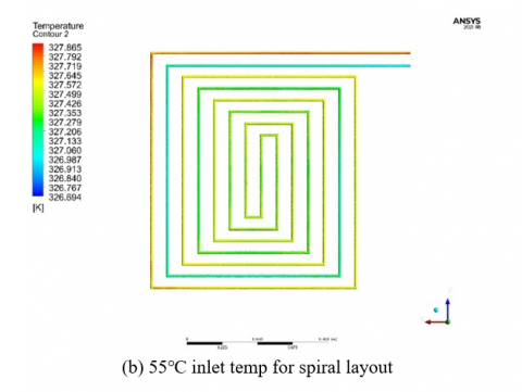
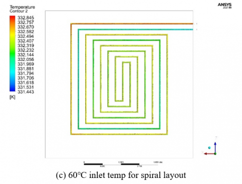
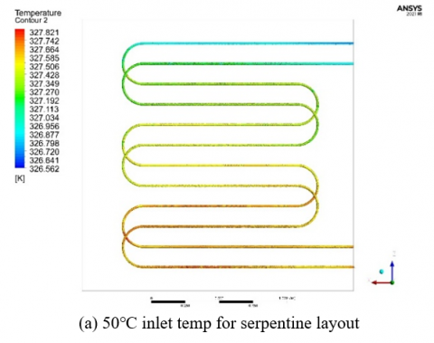
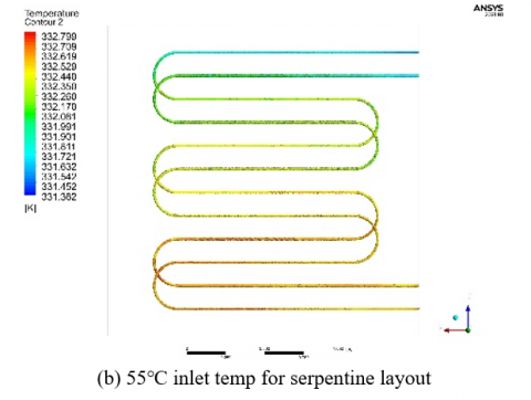
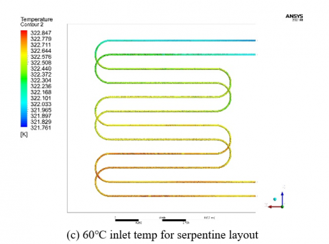
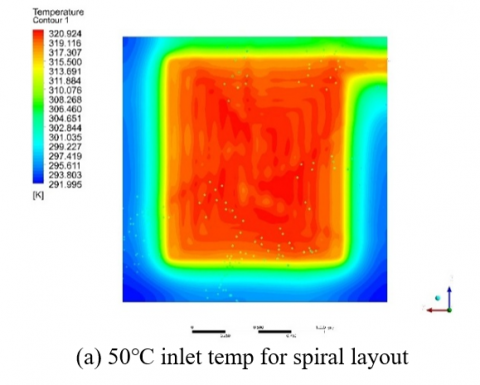
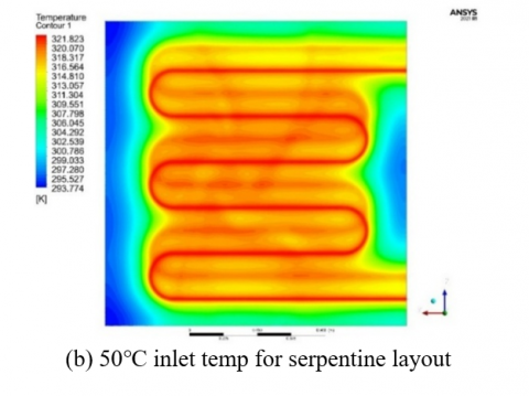
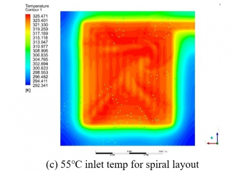
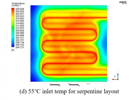
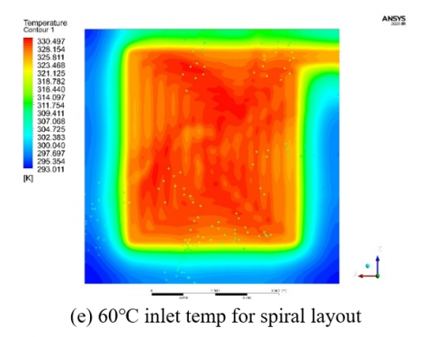
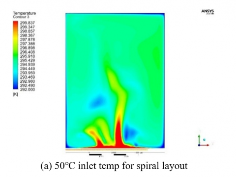
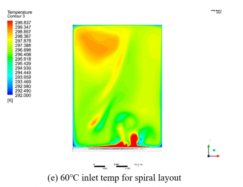
This paper uses a case study for mathematical simulations to forecast temperature diffusion and the degree of homogenization in the underfloor heating system. Where, Figure 3 (a), (b), (c) and Figure 4 (d), (e), (f) showed the counter for distribution temperature for the two layout’s pipe (Spiral & serpentine configuration) respectively in the difference inlet water temperature as (50, 55 and 60℃) at flowrate 12Lit/min. and found the differences between two layouts its near and saved about 0.5℃.
Figure 3. Temperature distribution for spiral pipes at different inlet temperatures
Figure 4. Temperature distribution for serpentine pipes at different inlet temperatures
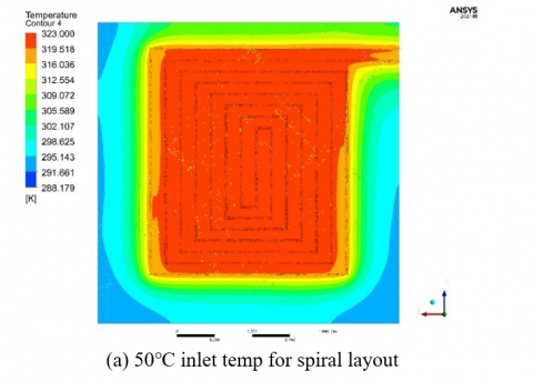
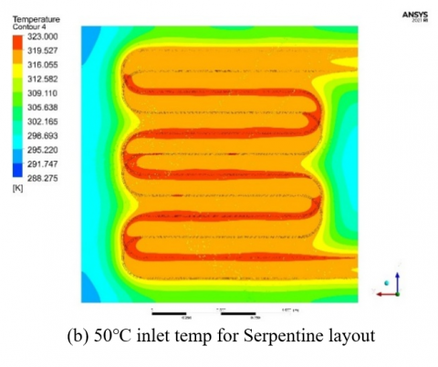
Figure 5 illustrates the temperature contour map of the radiant surface at an intake flow rate 12 Lit/min and inlet temperatures of 50, 55, and 60℃. This is executed to systematically assess the temperature homogeneity of the radiating surface. The minimum temperature for the facets was documented, indicating a distribution of roughly 18℃ for the spiral pipes and around 20℃ for the serpentine pipes. The maximum facet temperature was recorded at the edge of the radiant surface, particularly in regions with spiral or serpentine pipes, with values of 57 and 58℃, respectively. The discrepancy between the maximum and minimum temperature attained was 38℃, exceeding our forecasts for the concrete radiant roof. An optimal arrangement of the serpentine pipes will improve the consistency of temperature dispersion over the radiant surface.
Figure 5. Temperature distribution at surface floor
Figure 6 the temperature contours of the XY plane at a steady state, derived from a range of varying inlet temperatures (Ti=50, 55, and 60℃, mass flow rate=12 Lit/min), The temperature contours for input water temperatures of 50℃, 55℃, and 60℃ display analogous distribution patterns, with notable variations in the extent and intensity of the thermal gradients: At 50℃, the temperature range of the floor is significantly lower, with maximum temperatures near the pipes reaching moderate levels, while the peripheral areas exhibit bigger cold zones. This signifies less heat transfer relative to elevated inlet temperatures. 55℃: This state indicates a more equilibrated thermal gradient. The surface attains a temperature range nearer to the preferred comfort range (24-29℃), with marginally reduced chill zones relative to the 50℃ scenario. The 60℃ condition has the most extensive overall temperature range and reduced cool zones, as illustrated in the image. The elevated inlet temperature facilitates expedited heat transport, resulting in increased surface temperatures at the periphery, albeit with a possibility of uneven heat distribution. Increasing the input temperature diminishes cool zones and improves thermal distribution, but at the expense of elevated energy usage. The 55℃ scenario seems to offer an ideal equilibrium, reducing cool areas while sustaining agreeable surface temperatures without undue heating. At 50℃, the distribution is non-uniform, exhibiting distinct temperature gradients emanating from the pipe. Colder areas prevail at the peripheries, indicating inadequate heat distribution. At 55℃, the distribution enhances, accompanied by a decrease in chilly zones. The middle sections exhibit enhanced homogeneity, and the edge losses are somewhat reduced in comparison to 50℃. At 60℃, optimal homogeneity is noted in the center regions, however minor overheating at the pipe and boundary effects at the peripheries remain evident. As described above, homogeneity improves with increasing inlet temperature; however, at 60℃, the benefits lessen, and the risk of overheating escalates. 55℃ provides optimal homogeneity. The thermal comfort range of 24-29℃ is attained under various scenarios at 50℃. Limited comfort zones are primarily attained near the pipe. Peripheral regions exhibit performance levels that are below the acceptable range. at 55℃ The expanded comfort zone is achieved, with much of the floor surface falling within or close to the optimal range, resulting in the most energy-efficient condition at 60℃. The overall floor surface surpasses the lower comfort threshold; however, areas adjacent to the pipe may marginally exceed the upper limit, which could result in inefficiencies or discomfort. The analysis indicates that 55℃ achieves an optimal balance between comfort and energy efficiency, whereas 60℃ may result in unnecessary energy expenditure due to overheating.
Figure 6. Temperature distribution for air inside room
Figure 7 analysis of temperature distribution inside slab for the spiral design of a slab is characterized by a centralized heat distribution, with the highest temperatures concentrated in the center and decreasing towards the periphery. This design is effective at 50℃, but chill zones are present at the peripheries due to restricted lateral heat transport. At 55℃, the floor attains a more uniform temperature distribution, diminishing chilly areas. At 60℃, the temperature gradient becomes more uniform, yet the central regions show minimal overheating. The serpentine configuration generates unique longitudinal heat bands aligned with pipe runs, with cooler areas at the pipe ends where water leaves. At 50℃, cooler areas prevail between pipe runs, indicating irregular heat distribution. At 55℃, the surface experiences enhanced thermal diffusion, yet banding effects continue. Due to its continuous inward-outward design, the spiral configuration ensures more consistent heat distribution across the floor, especially at elevated inlet temperatures.
The spiral configuration attains enhanced uniformity across all intake temperatures, especially at 55℃ and 60℃, where most of the surface stays within an optimal temperature range. The shape facilitates even heat distribution from the middle outward, minimizing the presence of hot and cold areas. The serpentine pattern exhibits difficulties with homogeneity, particularly at lower inlet temperatures (50℃), where cooler zones are more evident between the pipes. At 60℃, thermal homogeneity enhances; however, the banding effect persists due to the linear configuration of pipes, which constrains lateral heat distribution. The spiral configuration surpasses the serpentine design in terms of uniform heat distribution, rendering it more appropriate for applications necessitating continuous surface temperatures. Spiral Layout: At 55℃, the spiral configuration attains optimal thermal comfort, with most areas within the comfort range (24-29℃) while preventing overheating. This inlet temperature seems to achieve an optimal equilibrium between comfort and energy efficiency. At 60℃, warming in the core sections may result in minor inefficiencies, however the design ensures superior coverage across the surface. Serpentine Layout: At 50℃, the serpentine configuration fails to ensure comfort owing to irregular heat distribution. At 55℃, thermal comfort enhances; yet the banding effect induces localized discomfort. At 60℃, most of the surface lies within the comfort range; nonetheless, the design is less efficient than the spiral configuration.
Figure 7. Temperature distribution inside the slab
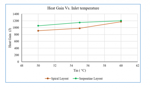
The improvement percentage in heat gain for serpentine pattern over spiral layout at inlet temperatures (50, 55, and 60℃) is around 12.22%, 15.05%, and 10.29%, respectively, as shown in Figure 8. It should be mentioned that the optimal percentage occurs at 55℃.
Figure 8. Temperature inlet vs. heat gain
The flooring assembly comprises five categories: floor covering, a concrete layer, a network of pipes, insulation, and a slab. The insulation plate fixes a network of PEX pipes and embeds them within the concrete layer. This material of pipes is the most utilized in such projects, principally because of its long-term durability, ease of implementation, and corrosion resistance. The concrete slab retains heat and radiates it into the rooms with the hot-water underfloor heating system, adhering to the NF DTU 65.14 P1 standard [26]. Referring to Figure 9, which shows the validation between this work and Yassine & Mohammed, find the serpentine in this work above about 20 to 25%, while for the spiral layout, the work is about 27 to 30%.
Figure 9. Temperature distribution inside the slab
This study underscores the importance of selecting the appropriate radiant floor heating design based on specific operational conditions. By providing a comprehensive comparison of two designs under varying inlet temperatures and flow rate, the findings contribute to the development of more efficient and user-friendly radiant heating systems. Preliminary results indicate that the spiral layout achieves better heat distribution uniformity at lower inlet temperatures, while the serpentine layout demonstrates higher efficiency at elevated temperatures.
The authors would like to acknowledge to the respected editors of International Journal of Heat and Technology and the respected reviewers for their comments that clearly enhance the manuscript. Also, the authors would like to thank the Mechanical Department - Engineering Collage at University of Baghdad for their support.
|
CP |
specific heat, J. kg-1. K-1 |
|
g k |
gravitational acceleration, m.s-2 thermal conductivity, W.m-1. K-1 |
|
Nu |
local Nusselt number along the heat source |
|
Greek symbols |
|
|
a |
thermal diffusivity, m2. s-1 |
|
b |
thermal expansion coefficient, K-1 |
|
n |
Kinamatic viscocity m2.s-1 |
|
µ |
dynamic viscosity, kg. m-1.s-1 |
|
Subscripts |
|
|
s |
slab |
[1] Oubenmoh, S., Allouhi, A., Mssad, A.A., Saadani, R., Kousksou, T., Rahmoune, M., Bentaleb, M. (2018). Some particular design considerations for optimum utilization of under floor heating systems. Case Studies in Thermal Engineering, 12: 423-432. https://doi.org/10.1016/j.csite.2018.05.010
[2] Tota-Maharaj, K., Adeleke, B.O. (2022). Thermal performance of radiant floor heating systems concrete slabs. Proceedings of the Institution of Civil Engineers - Energy, 176(2): 77-88. https://doi.org/10.1680/jener.21.00118
[3] Olesen, B.W. (2002). Radiant floor heating in theory and practice. ASHRAE Journal, 19-24.
[4] Werner-Juszczuk, A.J. (2019). Analysis of the use of radiant floor heating as a cooling system. Proceedings, 16(1): 23. https://doi.org/10.3390/proceedings2019016023
[5] Eswiasi, A., Mukhopadhyaya, P. (2021). Performance of conventional and innovative single u-tube pipe configuration in vertical ground heat exchanger (VGHE). Sustainability, 13(11): 6384. https://doi.org/10.3390/su13116384
[6] Bishara, N., Schulz, T., Gecks, J., Plagge, R., Wehsener, J. (2017). Thermal optimization and performance analysis of an innovative wooden radiant heating system made for room temperature control—Laboratory and numerical investigation of prototypes. Energy and Buildings, 138: 569-578. https://doi.org/10.1016/j.enbuild.2016.12.091
[7] Kong, X., Chang, Y., Fan, M., Li, H. (2023). Analysis on the thermal performance of low-temperature radiant floor coupled with intermittent stratum ventilation (LTR-ISV) for space heating. Energy and Buildings, 278: 112623. https://doi.org/10.1016/j.enbuild.2022.112623
[8] Almeida, R.M.S.F., da Silva Vicente, R., Ventura-Gouveia, A., Figueiredo, A., Rebelo, F., Roque, E., Ferreira, V.M. (2022). Experimental and numerical simulation of a radiant floor system: The impact of different screed mortars and floor finishings. Materials, 15(3): 1015. https://doi.org/10.3390/ma15031015
[9] Rashid, F.L., Hussein, A.K., Al-Obaidi, M.A., Alshammari, B.M., Ali, B., Hajlaoui, R., Boudabous, M.M., Kolsi, L. (2024). A review of radiant heating and cooling systems incorporating phase change materials. Journal of Thermal Analysis and Calorimetry, 149(15): 7891-7917. https://doi.org/10.1007/s10973-024-13193-6
[10] Park, B., Ryu, S.R., Cheong, C.H. (2020). Thermal comfort analysis of combined radiation-convection floor heating system. Energies, 13(6): 1420. https://doi.org/10.3390/en13061420
[11] Anigrou, Y., Zouini, M. (2024). Comparative numerical study of floor heating systems using parallel and spiral coil. Scientific African, 24: e02188. https://doi.org/10.1016/j.sciaf.2024.e02188
[12] Hooshmand, S.M., Zhang, H., Javidanfar, H., Zhai, Y., Wagner, A. (2023). A review of local radiant heating systems and their effects on thermal comfort and sensation. Energy Build, 296: 113331. https://doi.org/10.1016/j.enbuild.2023.113331
[13] Jasim, Q.K. (2023). Thermal performance of radiant floor thermal performance of radiant floor cooling system with phase change material. University of Baghdad, Iraq.
[14] Hu, R., Niu, J.L. (2012). A review of the application of radiant cooling & heating systems in Mainland China. Energy and Buildings, 52: 11-19. https://doi.org/10.1016/j.enbuild.2012.05.030
[15] Liu, Z., Wei, Z., Teng, R., Sun, H., Qie, Z. (2023). Research on performance of radiant floor heating system based on heat storage. Applied Thermal Engineering, 231: 120812. https://doi.org/10.1016/J.APPLTHERMALENG.2023.120812
[16] Gür, M., Gürgenç, E., Coşanay, H., Öztop, H.F. (2025). Solar-assisted radiant heating system with nano-B4C enhanced PCM for nearly zero energy buildings. Case Studies in Thermal Engineering, 65: 105544. https://doi.org/10.1016/j.csite.2024.105544
[17] Cui, M., Ning, B., Wu, X., Kim, M.K., Yang, B., Tian, Z., Liu, J. (2024). The development of radiant floor cooling system (RFCS): System type, control strategy, and application. Results in Engineering, 23: 102544. https://doi.org/10.1016/j.rineng.2024.102544
[18] Carnieletto, L., Kazanci, O.B., Olesen, B.W., Zarrella, A., Pasut, W. (2024). Combining energy generation and radiant systems: Challenges and possibilities for plus energy buildings. Energy and Buildings, 325: 114965. https://doi.org/10.1016/j.enbuild.2024.114965
[19] Sobhy, I., Brakez, A., Benhamou, B. (2017). Energy performance and economic study of a solar floor heating system for a Hammam. Energy and Buildings, 141: 247-261. https://doi.org/10.1016/j.enbuild.2017.02.044
[20] Radiant floor heating — Alternative to forced-air heating is solar-powered, too an interview with Stephen Heckeroth - Backwoods home magazine. https://www.backwoodshome.com/radiant-floor-heating/.
[21] Hasan, H.A., Hassoon, A.S. (2023). Thermal performance investigation of finned latent heat storage of shell-and-tube, shell-and-nozzle, and shell-and-reducer models. Heat Transfer, 52(7): 4755-4773. https://doi.org/10.1002/htj.22906
[22] Oubenmoh, S., Allouhi, A., Ait Mssad, A., Saadani, R., Kousksou, T., Rahmoune, M., Bentaleb, M. (2018). Some particular design considerations for optimum utilization of under floor heating systems. Case Studies in Thermal Engineering, 12: 423-432. https://doi.org/10.1016/j.csite.2018.05.010
[23] K-epsilon models-CFD-Wiki, the free CFD reference. https://www.cfd-online.com/Wiki/K-epsilon_models.
[24] Ahsan, M. (2014). Numerical analysis of friction factor for a fully developed turbulent flow using k–ε turbulence model with enhanced wall treatment. Beni-Suef University Journal of Basic and Applied Sciences, 3(4): 269-277. https://doi.org/10.1016/j.bjbas.2014.12.001
[25] Simou, Z., Hamdaoui, S., Oubenmoh, S., El Afou, Y., Babaharra, O., Mahdaoui, M., Ait Msaad, A. (2024). Thermal evaluation and optimization of a building heating system: radiant floor coupled with a solar system. Journal of Building Pathology and Rehabilitation, 9(1): 24. https://doi.org/10.1007/s41024-023-00375-2
[26] French Standard - NF DTU 65.14 P1-2 - Building Works - Installation of Water Floors: Heating, Cooling, and Reversible - Part 1-2: General Criteria for Material Selection, Jul. 2023. https://standards.ie/en-ie/standards/nf-dtu-65-14-p1-1-2-2023-1337639_saig_afnor_afnor_3214972/.