Sara Touzani![]() | Yousuf Alhendal*
| Yousuf Alhendal*![]()
© 2024 The authors. This article is published by IIETA and is licensed under the CC BY 4.0 license (http://creativecommons.org/licenses/by/4.0/).
OPEN ACCESS
This paper investigates, experimentally along with three-dimensional CFD simulation, the variation in heat transfer coefficients of a heated plate located with different inclination angles (0 ≤ α ≤ 90°) and aspect ratios (0.25 ≤ AR ≤ 2). The considerate airflow is at different speeds from 4-32 m/s. The CFD model was simulated by Ansys-Fluent, solving the discretized equations using finite volume method. The experimental data align with CFD results with a relative error between 1.09% and 10.74%. Taking into consideration the plate width enhances the heat transfer coefficient compared to 2D study. Regardless of the inclination angle and the aspect ratio, heat transfer is enhanced with high inlet velocity. By increasing the inlet velocity, heat transfer coefficient decreases with the increment of AR at α = 30°. Different average correlations were obtained between heat transfer coefficient with inlet air velocity, and between average Nusselt number with Reynolds number. A relative error of -18% to 15% was obtained between the correlated and calculated Nusselt numbers. A general correlation linking average Nusselt number to Reynolds number, angle of inclination and heated plate aspect ratios, was also elaborated.
forced convection, inclined plate, angle of inclination, aspect ratio, CFD, correlation
Forced convection is a complex mode of energy transfer that combines fluid motion with heat transfer. Many applications related to this phenomenon exist such as wind-loaded buildings, solar panels and heat sinks [1-3]. Mostly, solar panels can be modeled as inclined surfaces. Therefore, optimizing the parameters controlling forced convection on inclined plates, as air velocity, angle of inclination or attack, heat generation and plate’s dimension, became a challenge.
Some authors analyzed the impact of air speed on heat transfer both experimentally and numerically [4-7]. By increasing the air velocity, the flow becomes turbulent. In order to simulate accurately those turbulences, the choice of a turbulence model is decisive. Reynolds Averaged Navier Stokes (RANS) models, especially standard k-ε and k-ω, are the most used for this kind of problems. Other models derived from the previously cited models exist like R k-ε, RNG k-ε, S k-ω and SST k-ω. Several researchers were interested in detecting the most adequate turbulence model. Therefore, the choice was based on testing the findings of those latter with experimental results. El-Shamy et al. [8] showed that SST k-ω was in better agreement with experiment compared to R k-ε, while, Karava et al. [9] found that k-ε was the most reliable.
Studies were also elaborated to evaluate the flow structure over a heated plate. Hourigan et al. [10] determined experimentally and numerically both the flow patterns and the thermal fields over a heated plate. They found that the heat transfer improved when the large vortices were formed. The sound was also used as a method to enhance the forced convection. Zuercher et al. [11] experimentally examined the stability of the boundary layer on the upper side of an inclined heated plate, while Griffiths [12] focused on an inelastic non-Newtonian fluid. Liu and Ren [13] simulated the transient convective flow adjacent to a heated plate and determined the parameters characterizing the thermal boundary layer flow.
In general, convective heat transfer correlations were established for laminar, mixed, and forced flows [14-17], which relate the Nusselt number to the Reynolds number and the angle of inclination. Altering the plate's inclination angle has a significant influence on heat transfer, leading to either enhancement or deterioration. According to Yang et al. [18], when the inclination angle becomes important, heat transfer is improved and flow separation also can occur. Alhendal and Touzani [19] showed that average Nusselt number increases with an angle of inclination varying from 0° to 20° approximately then decreases with higher angles (up to 90°). For a rectangular duct equipped by inclined baffles on its bottom wall, Arslan et al. [20] observed heat transfer improvement when the baffles inclination angle becomes steeper.
Another interesting parameter that can influence the flow as well as the heat transfer around the plate is the plate’s heating mode. Cossali [21] applied periodic heating condition and studied its impact on heat transfer coefficient. Shavazi et al. [22] considered a uniform flux on an inclined narrow flat plate. An increasing boundary layer thickness in the laminar region and uniform temperature distribution in turbulent region, were observed. Turgut et al. [23] examined numerically heat transfer over an inclined flat plate with unheated starting length with two boundary conditions: constant temperature and uniform flux. In order to enhance heat transfer, Sasaki and Ashiwake [24] attached rectangular grids on the inclined plate. An improvement of 20% was observed compared to without grids case.
Most researches mentioned above were interested in understanding the interaction between the air flow around the inclined plate and heat transfer, but the numerical part was mostly bidimensional. Thanks to developed CFD techniques, 3D studies became performed. Roy et al. [25] presented a three-dimensional study of an inclined surface with a heating pad in the middle, where heat transfer coefficients were determined numerically and experimentally. Moreover, heat transfer coefficient was calculated either locally or as an average on the inclined plate for a fixed plate’s dimension. In a 3D numerical study, Salhi et al. [26] showed that the presence of inclined baffles in a rectangular channel generated vortices inducing a mixing phenomenon, which leads to heat transfer rate’s improvement. The dimension of the plate is also an important parameter. Motwani et al. [27] were interested in studying the impact of two aspect ratios on heat transfer coefficient for different angle of plate’s inclination. Lately, Shademan and Naghib-Lahouti [28] investigated aspect ratio effect on airflow over an inclined flat plate using Large Eddy Simulation (LES) turbulence model.
Due to the lack in tridimensional studies as well as the effect of plate’s aspect ratio on heat transfer over inclined heated plate, the aim of this paper is to set out a comprehensive experimental and CFD analysis of this latter. This also includes predictions about the general heat transfer correlation, h, and general correlations for the average Nusselt number, Nu, with angle of inclination 0 ≤ α ≤ 90°, Reynolds number 63848 ≤ Re ≤ 319403, and aspect ratio 0.25 ≤ AR ≤ 2.
The experiments were conducted in a test glass apparatus (Figure 1). Detailed description of the different parts of the present experimental setup and measuring instruments, are presented above.
The major components of the experiment test setup are a 500 mm long duct with a centrifugal suction fan rated at 3.67 kW and a 300 x 300 mm square channel. The duct is coupled to a variable speed inverter, which allows the wind speed to be varied from 3.8 to 20 m/s, resulting in 67000 ≤ Re ≤ 367000. By utilizing a hot wire anemometer with an accuracy of 0.01 m/s, the wind speed profile is ascertained through the duct segment. A unique protractor mechanism, which can adjust the plate's inclination angle from 0° to 90° based on its dimensions, attaches the heated plate to the test section. An electric heater was used to heat the plate from below, and as seen in Figure 2, insulation was placed on the side opposite the heating element to prevent heat loss from the edges. A digital micrometer measuring pressure drop along a plate with an accuracy of 1 N/m2 is used. The calculated uncertainties for the measurements of pressure drop and wind speed were ±1% and ±4% of the reading, respectively. Measurements of pressure and velocity are taken in accordance with the study [29]. K-type thermocouple probes were fitted on a logarithmic scale to the plate's horizontal and vertical axis, with a 0.5°C uncertainty. K-type thermocouple probes were used to measure the air temperatures upstream and downstream of the inclined plate using three and six grid points, respectively. Via a switch box, a digital thermometer with a predetermined 0.5°C degree of uncertainty is attached to every thermocouple. It took about 40-50 minutes to see a constant modulus measurement experiment, indicating that the duration was adequate to establish steady state.
1- Motor. 2- Air blower. 3- Flexible joint. 4- Transformation duct. 5- Test section duct. 6- Main duct. 7- Honeycomb. 8- Diffuse intake.
Figure 1. Schematic experimental setup
Figure 2. Heating plate, heater assembly and insulator
Measurements of the different parameters are carried out during the experimental runs as follows:
- The electric power input to the main heater was determined separately by measuring the digital watt meter.
- The mass flow rate of air was indicated by using the anemometer vane.
- The heating surface temperatures were measured at 13 different positions to ensure their temperature’s uniformity.
- The readings of two thermocouples fixed on the front, and five in left of the wind tunnel in the working sections were measured.
- Heat flowing by conduction from the edges of the heating plate was determined with the help of the readings of two thermocouples embedded in the foam and the amiant.
Before each test run, the heaters wires were checked by measuring the electric Resistance for each one individually.
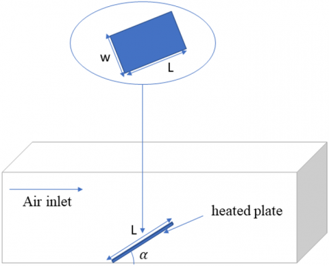
The computational field is depicted in Figure 3 as a rectangle with an inclined heated plate with an ignored thickness, length L, and width w inside of it. The plate has an angle of α and is heated using flux. The division of the plate's length by its width (AR = L/w) yields the aspect ratio AR. The turbulent, incompressible flow has an entrance velocity (V) that ranges from 4 to 32 m/s. A uniform flow velocity is defined by the flow limit, which is three times the plate's length. The pressure is null at the plate's minimum length, and no slip condition is given to the surface of the plate or any other surfaces that limit the computing field.
Figure 3. 3D problem configuration
The equations governing the phenomenon are the three equations of conservation (mass, momentum, and energy). They can be expressed as the following:
Mass:
∂ρ∂t+div(ρ→v)=0 (1)
Momentum:
∂(ρ→v)∂t+∇⋅(ρ→v→v)=−∇p+ρ→g+μΔ→v (2)
Energy:
∂(ρE)∂t+∇⋅(→v(ρE))=kΔT (3)
The conversion formula for the k-ε RNG model is:
∂∂t(ρk)+∂∂xi(ρkui)=∂∂xj(αkμeff∂k∂xj)+Gk+Gb−ρε+Sk (4)
∂∂t(ρε)+∂∂xi(ρεui)=∂∂xj(αεμeff∂ε∂xj)+C1εεk(Gk+C3εGb)−C2ερε2k−Rε+Sk (5)
where, ui the projection of →v depending on the axis. Gk=−ρ¯u′iu′j∂uj∂xi,Rε=cμρξ3(1−ξ/ξo)1+θξ3ε2k, Gb=giμtρPrt∂ρ∂x′i,C3ε=tanh|vu|,Sk=ξε.
The model constants; C1ε,C2ε,αk,αε,ξo and θ in Eqs. (4) and (5) are: C1ε=1.42; C2ε=1.68; αεk; ξ=4.34; and θ=0.012, turbulent kinetic energy is represented by Gξ while turbulent kinetic energy produced by buoyant forces and velocity, respectively, is represented by Gb. For k and ε,α,k and αε represent the reciprocal of (Pr).
For the energy equation, it becomes as the following:
∂(ρE)∂t+∂∂xi(ui(ρE+p))=∂∂xj(keff∂T∂xj+ui(τij)eff)+Sh (6)
With E, keff and (τij)eff representing the total energy, the effective thermal conductivity and the deviatoric stress tensor respectively; which can be formulated as:
(τij)eff=μeff(∂uj∂xi+∂ui∂xj)−23μeff∂uk∂xkδij (7)
The Eqs. (1)-(7) will be solved numerically utilizing Ansys Fluent software [30].
Pressure drag force coefficient is expressed as below:
Cd=2Δpρu20 (8)
With u0 being the velocity of the undistributed air flow and Δp being the pressure difference.
The Nusselt number is determined to assess the heat transfer. Expression of the local Nusselt number is:
Nux=qpXp(Tp−Tb)K (9)
With TP representing the plate temperature, Tb representing the bulk air temperature, K representing air thermal conductivity, and qp representing the heat flux at point p on the plate.
The average Nusselt number, Nu, represents the average of the local Nusselt numbers computed across the plate, expressed as:
Nu=hlK (10)
where, h for the entire plate is:
h=qA(Ts−T∞) (11)
where, A is changed by changing the aspect ratio, AR.
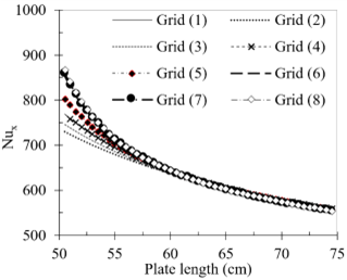
To make sure that the grid density adaptation has no effect on the simulation's result, a mesh sensitivity study is performed. By expanding the cells along the X and Y axis, the total number of cells changed for each computational domain, ranging from 21300 to 118428. It maintains ∆z at 0.1 mm along the Z axis. It was determined that the average drag force coefficient and the local and average Nusselt numbers will almost always converge regardless of the grid size. Grid (7) is the best grid in this scenario since it uses less CPU memory and time to get results that are comparable to a very fine grid (Table 1 and Figure 4).
Table 1. Average drag coefficient for the studied grids at α=0°, Re=2.74x10⁵ and Pr=0.74
|
Grid |
(∆x, ∆y) |
Number of Cells |
Cd (Average Drag on the Plate) |
|
(1) |
0.50 × 0.50 |
21300 |
0.00407 |
|
(2) |
0.40 × 0.40 |
26625 |
0.00400 |
|
(3) |
0.30 × 0.30 |
35571 |
0.00391 |
|
(4) |
0.25 × 0.25 |
42600 |
0.00387 |
|
(5) |
0.20 × 0.20 |
53250 |
0.00384 |
|
(6) |
0.15 × 0.15 |
70929 |
0.00382 |
|
(7) |
0.10 × 0.10 |
106500 |
0.00384 |
|
(8) |
0.09 × 0.09 |
118428 |
0.00382 |
Figure 4. Distribution of local Nusselt number over the plate for the studied grids
The experiment and CFD cases were carried out within an average air velocity between 2-20 m/s and 4-32 m/s respectively. The considered Reynolds number range is between 63848 and 319403. Both 2D and 3D numerical simulations and experiments were used to analyze the airflow on heated inclined flat plates for angles of inclination α varying from 0° to 90° and different aspect ratios (0.25 ≤ AR ≤ 2).
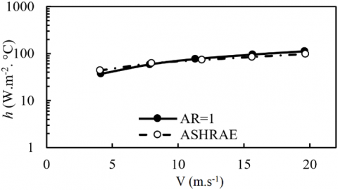
Before elaborating the 3D simulations, the CFD for AR=1 and α = 0° was compared to the correlation given by ASHRAE [29]. As it is noticed from Figure 5, the calculated heat transfer coefficient (h) is quietly similar to the correlated one with a relative difference between approximatively 2% and 14% observed at V= 8m/s and V=20 m/s respectively. The same tendency is noticed for both curves; the heat transfer increases with higher air inlet velocity.
In a previous work [19], heat transfer coefficient was found to be decreasing from α = 30°. As noticed from Figure 6, a vortex is created on the first edge of the plate helping the heat transfer improvement all over the plate. However, with the angle of inclination increment, the airflow becomes hindered due to the plate’s resistance which weakens the created vortex. In fact, when the inclination angle is high, an important skin friction occurs as a result of the created boundary layer around the plate. This latter leads to heat dissipation and therefore decreases the heat transfer coefficient on the plate.
Figure 5. Validation with correlation from ASHRAE [29]
In order to have more realistic results, the width of the plate is taken into account in the following paragraphs.
Figure 6. Streamlines for α = 20°, α = 30° and α = 60° for 2D case at V=20 m/s
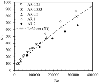
For α = 30°, the variation of average Nusselt number with Re is presented in Figure 7 for 3D results where 0.25 ≤ AR ≤ 2 and 2D case. Independently of the plate’s dimension, Nu increases with Re augmentation as observed for 2D case. However, when Re ≤ 100000, Nu decreases slightly for AR increment. Beyond Re = 100000, Nu decreases more for higher AR. By increasing the aspect ratio, the surface of exchange becomes important but leads to more skin friction, which impacts negatively the heat transfer.
Another interesting constatation is that for AR= 1, Nu is higher than all cases, regardless of Re. This can be related to the shape of the plate. For AR = 1, the plate is a square while for the other AR it becomes a rectangle. The square shape has less surface; thus, less friction occurs with the airflow. Compared to the 2D case, the impact of improving the surface of contact is obvious. More surface offers better heat transfer. As noticed, Nu can be correlated to Re in a linear or power empirical formula. Therefore, we will present these two types of correlations to see which one is more adequate for each studied case depending on AR and α.
The following empirical relationship formula of linear and power law are suggested for both dimensional and non-dimensional forms:
h = a⸳V + b (12)
h = c⸳Vm (13)
Nu = d⸳V + e (14)
Nu = f⸳Vn (15)
Figure 7. Comparison between Nu vs. Re for different AR and 2D case
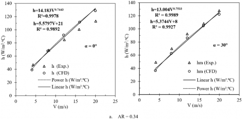
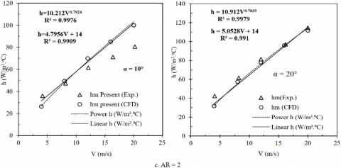
Figure 8. Average heat transfer coefficients vs. V for different angles of inclination and AR
Figure 9. Average Nu vs. Re for different angles of inclination and AR
Average heat transfer coefficient and Nusselt number are presented in function of inlet air velocity and Reynolds number respectively, experimentally as well as numerically, for different angles of inclination from 0⁰ to 90⁰ and aspect ratios AR= 0.34, 1 and 2 (Figures 8 and 9). Simulation results are in good agreement with experimental data for most studied angles. Table 2 shows a relative error between experimental and numerical heat coefficients for AR=1, varying between 1.67% to 11% approximatevely. This difference can be related to the measurments uncertainty and numerical errors. However, for α = 0°, α = 10°, and α = 90°, depending on AR, the two curves (experiment and CFD) become distant for higher V and Re. In experiment, when the velocity is very high therefore Re is important, the airflow submerging the plate for those particular angles, is facing hydrodynamic and thermal boundary layers that one overpowers the other depending the angle of inclination creating turbulences that can lead the plate to vibrate. Actually, McCormick et al. [31] observed the plate vibration experimentally when the velocity is high, showing that it impacts heat transfer coefficient values. For all cases, we can see that the power law is the most suitable to correlate average heat transfer coefficient and Nusselt number for all angles with R2 very close to 1.
Table 2. Comparison between experimental and numerical convective coefficients for AR =1
|
V m/s |
α° |
h exp W/ m2. K |
h num W/ m2. K |
Relative Error (%) |
|
8.32 |
0 |
44.62 |
49.41 |
10.74% |
|
16.33 |
0 |
73.34 |
75.84 |
3.41% |
|
20.31 |
0 |
86.72 |
88.17 |
1.67% |
|
3.9 |
40 |
27.05 |
26.20 |
3.14% |
|
8.15 |
40 |
47.71 |
47.19 |
1.09% |
|
20.44 |
40 |
88.92 |
91.79 |
3.23% |
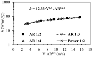
At first, a correlation of average heat transfer coefficient as a function of air inlet velocity and the aspect ratio at α = 0° is elaborated. It was obtained by taking the average values of the constant variables’ correlations for the 3D plates with aspect ratio 0.25,0.33,0.5 at α = 0° (Figure 10). Then the found average value from this process is plotted against (V·AR0.3), and the following correlation for h is obtained:
h = 12.33·V0.8 ⸳AR0.24 (16)
For 4 ≤ V ≤ 24 and 0.25 ≤ AR ≤ 1
Figure 10. Correlation for heat transfer coefficient, h, vs. V and AR of (0.25 to 0.5)
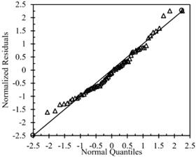
Figure 11. Residual normal probability plot
A general correlation relating average Nusselt number to Reynolds number, angle of inclination and aspect ratio is generated from the different data that we collected for the following ranges cover:
0 ≤ α ≤ 90° for
63848 ≤ Re ≤ 319403
and 0.25 ≤ AR ≤ 1.
the correlation expression is:
Nu = 0.1·Re0.72(1-sin(α)-0.02AR-0.11) (17)
As shown in Figure 11, this general correlation presents a good association between the considered variables. The maximum error between the normalized residues and the normalized quantities is between -18% and 15%.
Airflow over an inclined heated plate aroused researchers’ interest due to its various applications (solar panels, building roofs…). The majority of existing literature on this subject either simplifies flat plates by disregarding their width or focuses on laminar flow scenarios. In the present paper, the influence of different aspect ratios and angles of inclination is analyzed on heat transfer coefficient, experimentally and numerically in 3D. The covered Reynolds number, inclination angle and aspect ratio ranges are 63848 ≤ Re ≤ 319403, 0⁰ ≤ α ≤ 90⁰ and 0.25 ≤ AR ≤ 2. The following results were obtained:
Those correlations can be beneficial for engineering applications designs especially for sizing solar panels.
|
CFD |
computational fluid dynamics |
|
div |
divergence (div(→v)=∂u1/∂x+∂u2/∂y+∂u3/∂z) |
|
f |
friction factor, dimensionless |
|
E |
energy, joule |
|
g |
gravitational acceleration, m.s-2 |
|
h |
Heat transfer coefficient, w.m-2. k-1 |
|
J |
Coulburn factor, dimensionless |
|
k |
thermal conductivity, w.m-1. k-1 |
|
L |
flat plate length, m |
|
Nu |
Nusselt number, dimensionless |
|
Pr |
Prandtl number, dimensionless |
|
∆P |
pressure drop, N/m2 |
|
PDEs |
partial differential equation |
|
Re |
Reynolds number, dimensionless |
|
s |
source term |
|
T |
temperature, K |
|
t |
time, s |
|
→v |
velocity vector, (u1, u2, u3) |
|
V |
air velocity, m/s |
|
x |
x coordinate, m |
|
y |
y coordinate, m |
|
Greek symbols |
|
|
ρ |
density, kg/m3 |
|
α |
thermal diffusivity, m2. s-1 |
|
β |
thermal expansion coefficient, k-1 |
|
µ |
dynamic viscosity, kg. m-1. s-1 |
|
κ |
turbulent kinetic energy, m2. s2 |
|
ε |
turbulent dissipation rate, m2. s3 |
|
Subscripts |
|
|
ɸ |
variable |
|
∂ |
rate of change |
|
x |
local distance, m |
[1] Alshayji, A., Ebrahim, S. (2020). Numerical simulation of heat transfer process in inclined roofs with radiant barrier system. Journal of Engineering Research, 8(2): 305-323. https://search.emarefa.net/detail/BIM-1494954.
[2] Kumar, D., Premachandran, B. (2022). Investigation of transition in a natural convection flow in an inclined parallel Plate Channel. International Communications in Heat and Mass Transfer, 130: 105768. https://doi.org/10.1016/j.icheatmasstransfer.2021.105768
[3] Haghighi, S.S., Goshayeshi, H.R., Zahmatkesh, I. (2024). Experimental investigation of forced convection heat transfer for different models of PPFHS heatsinks with different fin-pin spacing. Heliyon, 10(1): e23373. https://doi.org/10.1016/j.heliyon.2023.e23373
[4] Onur, N. (1993). Forced convection heat transfer from a flat-plate model collector on roof of a model house. Heat and Mass Transfer, 28(3): 141-145. https://doi.org/10.1007/BF01541111
[5] Adhikari, R.C., Wood, D.H., Pahlevani, M. (2020). An experimental and numerical study of forced convection heat transfer from rectangular fins at low Reynolds numbers. International Journal of Heat and Mass Transfer, 163: 120418. https://doi.org/10.1016/j.ijheatmasstransfer.2020.120418
[6] Mostafavi, A., Jian, A. (2021). Unsteady convective heat transfer from a flat plate with heat flux varies in space and time. International Journal of Heat and Mass Transfer, 172: 121084. https://doi.org/10.1016/j.ijheatmasstransfer.2021.121084
[7] Jha, A.K., Shukla, P., Khisti, P.M., Ghosh, P., Yadav, S. K. (2023). Investigation of onset of velocity transition in free convection over an inclined flat plate by PIV. Experimental Thermal and Fluid Science, 140: 110764. https://doi.org/10.1016/j.expthermflusci.2022.110764
[8] El-Shamy, A.R., Sakr, R.Y., Berbish, N.S., Messra, M.H. (2007). Experimental and numerical study of forced convection heat transfer from an inclined heated plate placed beneath a porous medium. In Al-Azhar Engineering Ninth International Conference, Cairo, Egypt.
[9] Karava, P., Jubayer, C.M., Savory, E. (2011). Numerical modelling of forced convective heat transfer from the inclined windward roof of an isolated low-rise building with application to photovoltaic/thermal systems. Applied Thermal Engineering, 31(11-12): 1950-1963. https://doi.org/10.1016/j.applthermaleng.2011.02.042
[10] Hourigan, K., Welch, L.W., Thompson, M.C., Cooper, P.I., Welch, M.C. (1991). Augmented forced convection heat transfer in separated flow around a blunt flat plate. Experimental Thermal and Fluid Science, 4(2): 182-191. https://doi.org/10.1016/0894-1777(91)90062-V
[11] Zuercher, E.J., Jacobs, J.W., Chen, C.F. (1998). Experimental study of the stability of boundary-layer flow along a heated, inclined plate. Journal of Fluid Mechanics, 367: 1-25. https://doi.org/10.1017/S0022112098001347
[12] Griffiths, P.T. (2017). Stability of the shear-thinning boundary-layer flow over a flat inclined plate. Proceedings of the Royal Society A: Mathematical, Physical and Engineering Sciences, 473(2205): 20170350. https://doi.org/10.1098/rspa.2017.0350
[13] Liu, Y., Ren, S. (2023). Convective boundary layer flow adjacent to an inclined and linearly heated semi-infinite plate. ASME Journal of Heat and Mass Transfer, 145(6): 062603. https://doi.org/10.1115/1.4056485
[14] Ramirez, C., Murray, D.B., Fitzpatrick, J.A. (2002). Convective heat transfer of an inclined rectangular plate. Experimental Heat Transfer, 15(1): 1-18. https://doi.org/10.1080/089161502753341834
[15] Sartori, E. (2006). Convection coefficient equations for forced air flow over flat surface, Solar Energy, 80(9): 1063-1071. https://doi.org/10.1016/j.solener.2005.11.001
[16] Palyvos, J.A. (2008). A survey of wind convection coefficient correlations for building envelope energy systems’ modeling. Applied Thermal Engineering, 28(8-9): 801-808. https://doi.org/10.1016/j.applthermaleng.2007.12.005
[17] Mahboub, C., Moummi, N., Moummi, A., Youcef-Ali, S. (2011). Effect of the angle of attack on the wind convection coefficient. Solar Energy, 85(5): 776-780. https://doi.org/10.1016/j.solener.2011.01.008
[18] Yang, S.A., Chae, M.S., Chung, B.J. (2020). Natural convection flow separation on the inclined plate depending on inclination and Pr. In Transactions of the Korean Nuclear Society Virtual Spring Meeting.
[19] Alhendal, Y., Touzani, S. (2023). Influence of inclination angles on convective heat transfer in solar panels. International Journal of Heat and Technology, 41(4): 808-814. https://doi.org/10.18280/ijht.410403
[20] Arslan, K., Ekiciler, R., Onur, N. (2023). Inclination angles effect on heat transfer and turbulent periodic flow in a duct-mounted flow-inclined baffles. Arabian Journal for Science and Engineering, 1-11. https://doi.org/10.1007/s13369-023-07903-9
[21] Cossali, G.E. (2005). Periodic heat transfer by forced laminar boundary layer flow over a semi-infinite flat plate. International Journal of Heat and Mass Transfer, 48(23-24): 4846-4853. https://doi.org/10.1016/j.ijheatmasstransfer.2005.06.005
[22] Shavazi, E.A., Torres, J.F., Hughes, G.O., Pye, J.D. (2018). Convection heat transfer from an inclined narrow flat plate with uniform flux boundary conditions. In Proceedings of the 21st Australasian Fluid Mechanics Conference, Adelaide, Australia.
[23] Turgut, O., Ozcan, A.C., Turkoglu, H. (2019). Laminar forced convection over an inclined flat plate with unheated starting length. Politeknik Dergisi, 22(1): 53-62. https://doi.org/10.2339/politeknik.403984
[24] Sasaki, S., Ashiwake, N. (2002). Enhancement of natural convection heat transfer from an inclined heated plate using rectangular grids. Heat Transfer — Asian Research: Co-sponsored by the Society of Chemical Engineers of Japan and the Heat Transfer Division of ASME, 31(5): 408-419. https://doi.org/10.1002/htj.10043
[25] Roy, S., Nasr, K., Patel, P., AbdulNour, B. (2002). An experimental and numerical study of heat transfer off an inclined surface subject to an impinging airflow. International Journal of Heat and Mass Transfer, 45(8): 1615-1629. https://doi.org/10.1016/S0017-9310(01)00276-9
[26] Salhi, J.E., Zarrouk, T., Hmidi, N., Salhi, M., Salhi, N., Chennaif, M. (2023). Three-dimensional numerical analysis of the impact of the orientation of partially inclined baffles on the combined mass and heat transfer by a turbulent convective airflow. International Journal of Energy and Environmental Engineering, 14(1): 79-94. https://doi.org/10.1007/s40095-022-00505-5
[27] Motwani, D.G., Gaitonde, U.N., Sukhatme, S.P. (1985). Heat transfer from rectangular plates inclined at different angles of attack and yaw to an air stream. ASME Journal of Heat and Mass Transfer, 107(2): 307-312. https://doi.org/10.1115/1.3247415
[28] Shademan, M., Naghib-Lahouti, A. (2020). Effects of aspect ratio and inclination angle on aerodynamic loads of a flat plate. Advances in Aerodynamics, 2: 1-23. https://doi.org/10.1186/s42774-020-00038-7
[29] Handbook, A.S.H.R.A.E. (1985). Fundamentals SI Edition, American Society of Heating. Refrigeration and Air-Conditioning Engineers, Inc., Atlanta, GA, 1200(0.0341): 0-2379.
[30] Fluent, 2013 User’s Manual, Fluent Inc., USA. https://www.fluid.tuwien.ac.at/322057?action=AttachFile&do=get&target=flu_ug.pdf.
[31] McCormick, D.C., Test, F.L., Lessmann, R.C. (1984). The effect of free-stream turbulence on heat transfer from a rectangular prism. ASME Journal of Heat and Mass Transfer, 106(2): 268-275. https://doi.org/10.1115/1.3246668