Ameer K. Salho*![]() | Dhafer A. Hamzah
| Dhafer A. Hamzah![]()
© 2024 The authors. This article is published by IIETA and is licensed under the CC BY 4.0 license (http://creativecommons.org/licenses/by/4.0/).
OPEN ACCESS
Stirred mixers are ubiquitous in industrial applications, operating optimally to achieve homogeneous mixing of liquids, gases, and solids. Improving mixer performance is critical for attaining high efficiency, low production costs, and high product quality. This review examines three key aspects of mixer optimization: power consumption, mixing time, and impeller geometry. The research aims to summarize a comprehensive review on mixing time and the experimental devices used to measure it. The effect of using impellers and changing their geometry on the power consumption, mixing efficiency, and mixing time. Power usage is a vital metric for evaluating mixer efficiency. Complex interplay between impeller design, operating conditions, and fluid properties governs energy consumption. Understanding and minimizing power requirements are essential for efficient, sustainable mixing operations. Mixing time also significantly impacts efficiency, relating directly to impeller geometry and fluid rheology. Reviewing research on mixing time highlights opportunities to reduce durations, boosting productivity. Impeller geometry, governing mixer design for target applications, represents another major optimization variable. Impeller selection plays a major role in stirred tanks, especially in chemical processing. Elucidating relationships between fluid dynamics and impeller configurations is thus necessary for developing effective, economical mixing solutions.
stirred tank, rotation domain, power number, mixing time, impeller geometry
Mixing processes are utilized in systems across many industries to improve homogeneity by transporting materials within mixing vessels. Liquid-liquid mixing promotes blending of multiple immiscible or partially miscible liquids. Gas-liquid mixing involves dispersing a gas phase into a liquid medium. Liquid-solid mixing aims to combine solid particles into a liquid suspension. Each mixing type has distinct challenges and applications. For example, liquid-liquid processes must overcome interfacial tension, while gas-liquid mixing contends with compressibility. Meanwhile, solid-liquid mixing requires overcoming sedimentation effects. Understanding the fundamentals of these mixing regimes is critical for achieving efficient homogenization and flow in industrial systems. The choice of mixing type depends on the specific requirements of the materials and desired outcomes of the process [1]. Stirred tank mixers are indispensable components in most industrial applications, from chemical processes, pharmaceutical manufacturing, and food processing to water treatments. In contemporary research focusing on stirred tank mixers, scholars predominantly direct their attention towards elucidating the fundamental traits inherent to these devices. Of particular interest are metrics such as energy consumption and mixing duration, which serve as vital indicators of their operational efficiency. Concurrently, scholars delve into detailing the intricate flow dynamics facilitated by these mixers, thus providing a comprehensive understanding of their functionality and performance. The design of these dynamic vessels is based on mixing various materials and efficiently homogenizing them to ensure product quality and performance. In the world of fluid dynamics, the complexity of stirred tank mixers is an important topic for investigation, innovation, and exploration. Research efforts in this field over the years have been undertaken to achieve optimal performance, which can be characterized in terms of reduced power consumed, reduced mixing times, and impeller geometry. A comprehensive understanding of stirred tank mixers is essential, especially with the development taking place in the industry driven by the goals of sustainability, cost-effectiveness, and the ever-pressing demand to increase the quality of the product. One of the important variables for mechanical engineering and chemical engineering is the rate of power consumption because it is closely related to the total cost of industrial operations. Therefore, it is better for mixing operations to be carried out with high mixing efficiency and the lowest rate of energy consumption [2]. There are many previous studies concerned with studying the power consumption rate in stirred tank mixers, as well as looking at mixing efficiency and mixing times [3, 4]. Using impellers with a variable number of blades, they demonstrated the energy consumption of stirred tanks in experimentally [5, 6]. It is possible to know and study the energy consumption inside stirred tanks using a multi-phase flow system, as in a study, Dohi et al. [4] that showed the energy consumption rate using a stirred tank and a three-phase gas-liquid-solid flow system. Paper et al. [7] investigated numerically the effect of using different impeller geometries and using laminar flow with different Reynolds numbers inside a baffled stirred vessel. They used four different types of impellers (Rushton turbine standard shape, Turbine Rushton with circle blade shape, Rushton turbine with the cut circular shape, Rushton turbine with the cut rectangular shape) and observed their effect on the energy consumption process, flow patterns, and pumping rate with the use of Reynolds numbers between (1-100). The results showed that the use of blades with different geometric shapes contributes to the process of improving the pumping rate and reduces energy consumption, in addition to improving the flow field for radial and axial velocities. They found that the use of (Turbine Rushton with circle blade shape) type impellers is the best and most effective compared to the other types used. The shape of the impellers used in mixers has a very effective role in mixing operations, and this in turn depends on the type of application [8], whether a high- or low-viscosity liquid is used, or in multi-phase mixing. Therefore, there are many different types of impellers for mixers, which can be classified according to the phase of the materials used (liquid, solid, gas) or if it is a viscous liquid, low viscosity, Newtonian, or non-Newtonian. For example, in their study, the researchers Amiraftabi et al. [9] used a spiral ribbon impeller in a stirred tank containing a diluted polymer rheological fluid (sodium carboxymethyl cellulose).
This review paper explores the complex world of stirred mixer optimization by closely examining three key performance factors: power consumption, mixing times, and impeller geometry. The aim is to synthesize research on these variables to provide insights into the fundamental principles and emerging technologies governing stirred mixer design. An extensive critical evaluation of the literature will be undertaken to better comprehend the interplay between these factors and their influence on mixer efficiency. Understanding power expenditure is crucial, as it directly impacts operating costs and sustainability. Likewise, mixing times relate strongly to throughput and productivity. Finally, impeller configurations underpin effectiveness of blending and homogenization. By reviewing the latest research on these parameters, this work seeks to highlight innovative mixer design approaches and opportunities for performance enhancement. The complexity of stirred mixer systems warrants ongoing investigation to meet pressing industrial needs for efficient, cost-effective and high quality mixing processes. This review will provide an in-depth perspective into the multifaceted problem of mixer optimization.
2.1 Power consumption
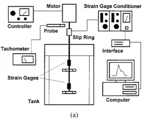
One of the significant challenges faced by engineers involved in the manufacturing of these mixers is the considerable power consumption. Clearly, numerous researchers in this field have dedicated their efforts in recent years to improving the power consumption rate of these mixers. This rate of power consumption holds substantial importance in evaluating both the heat transfers and mass transfer rates within the stirred tanks. As a result, the primary objective has shifted towards reducing power consumption by employing varying rotational speeds, thereby achieving efficient mixing in a short time frame whether utilizing a single or multiphase system. The reduction of power consumption has become imperative, as it directly translates to cost savings—a positive outcome for mixer manufacturers. Zadghaffari et al. [10] employed Roshten-6 turbines in their rotary mixer setup. The calculation of power consumption was accomplished in the form of a dimensionless factor (power number), utilizing numerical solution methods. The chosen solution model was the Large-eddy simulation, which was then juxtaposed with experimentally measured power consumption. The outcomes highlighted a minor 3% deviation from the experimental solution. Taghavi et al. [11] noted that the power number (Np) is related to the Reynolds number. They examined the impact of the locally consumed total power rate through experimental and numerical comparisons at different rotational speeds. This analysis encompassed both single-phase liquid and multi-phase liquid-gas scenarios, as depicted in Figure 1. The power number was measured from the relationship:
$N_P=\frac{P}{\rho N^3 D^5}$ (1)
ρ is the density of fluid of the in stirred tank, N impeller speed, D: impeller diameter.
The amount of power can also be measured directly by calculating the torque on the impeller:
$P=2 . \pi . N . \tau$ (2)
τ torque acting on the impeller, which can be calculated by:
$\tau=F . d_l$ (3)
F: force, dl: arm length.
Cheng et al. [12] experimentally verified the process of mixing water with immiscible liquids of different densities inside a stirred vessel. They examined power consumption values for various impeller types (Rushton disk turbine, half circle blade disk turbine, 45° pitched blade turbine down flow, 45° pitched blade turbine up flow at multiple rotational speeds. The results showed that power consumption ranged from 1.75 to 6 for the four distinct impeller types in the liquid-liquid phase, with power measured using a shaft torque meter. Figure 2 illustrates power number values plotted against Reynolds numbers, highlighting that the RDT impeller type has the highest power number value, while the PBTD and PBTU impeller types have the lowest values.
Figure 1. Comparison between experimental and numerical power number with different impeller speeds
Figure 2. Power number against Reynolds number [12]
There are many previous studies concerned with studying the amount of energy consumed in liquid-liquid system for mixers. Zadghaffari et al. [13] studied the effect of power consumption of two-phase flow inside an agitation tank with double Rushton blades using different rotational speeds numerically and experimentally. Murthy and JayantiI [14] investigated numerically the amount of power consumption expressed by the dimensionless parameter (power number) and the mixing time of an un-baffled stirred tank with eight turbine blades for three types of laminar flow, transitional and turbulent. Numerical results in their study were compared with the experimental results (O’Connell [15], Nagata [16], Stein [17]) where the results for different laminar region systems were shown in the Table 1 below. They used the empirical relationship in their study to compute the power number multiplied by (Re) for the laminar flow inside an agitation tank with three baffles and a straight blade:
$\mathrm{N}_{\mathrm{p}} \mathrm{N}_{\mathrm{Re}}=90 \mathrm{~S}^{0.327}\left(\frac{\mathrm{b}}{\mathrm{D}}\right)^{0.635 \mathrm{~s}^{-0.280}}$ (4)
where, $\mathrm{N}_{\mathrm{Re}}$ is the impeller Reynolds number, S: number of blades, b: blade width and D: diameter of the tank.
Nagata used the empirical relationship to calculate the power number for un-baffled vessel with laminar flow:
$\mathrm{N}_{\mathrm{p}}=\frac{\mathrm{A}}{\mathrm{N}_{\mathrm{Re}}}$ (5)
$A=14+\left(\frac{b}{D}\right)\left\{670\left(\frac{d}{D}-0.6\right)^{0.2}+185\right\}$ (6)
Table 1. Value of Np for laminar CFD solution and experimental correlation
|
RPM |
(NRe) |
($\mathbf{N}_{\mathrm{p}}$, NRe) from Correlations |
($\mathbf{N}_{\mathrm{p}}$, NRe) from CFD |
||
|
Stein |
Nagata |
O’Connell |
|||
|
50 |
0.48 |
88 |
122.7 |
130.2 |
81.7 |
|
100 |
0.96 |
88 |
122.7 |
130.2 |
81.5 |
|
200 |
1.92 |
88 |
122.7 |
130.2 |
82.7 |
|
500 |
4.8 |
88 |
122.7 |
130.2 |
86.9 |
|
1000 |
9.6 |
88 |
122.7 |
130.2 |
102.9 |
Kaiser et al. [18] demonstrated Experimentally the amount of input power in the bioreactors under the influence of turbulent flow inside an agitation tank. They aimed of the research was to minimize power consumption, which was expressed using the variable (power number) with various Reynolds number values and different rotational speeds. They showed that the value of the (Np) increases with higher (Re) and decreases when Reynolds numbers are low (100< Re <500) (from P = 6.3 to P≈ 3.3). The results also indicated the value of the (Np) remains constant when (Re) are in the fully turbulent state (Re > 104). Steiros et al. [19] Studied experimentally using three types of impellers for an un-baffled agitation tank, their effect on the amount of power consumption, and using a turbulent system. They compared between three types of blades, rectangular, fractal 1, fractal 2 to investigated the best power consumption. Their results prove the use of blades with fractal 1 reduces the amount of power number by (10%) compared to the rectangular impeller, as well as using the impeller with fractal 2 reduces by (3%) compared to the impeller with fractal 1.
Noted from many prior studies have clarified the amount of energy consumption inside the mixing tank, as the rate of energy consumption has a clear importance on the process of homogenization between different liquids [20], the process of gas dispersion within the liquid in addition to its importance in the process of heat transfer [21] and shear pressures. There are many devices that used to measure the amount of power either by calculating the amount of torque or using direct devices to measure the power input in the previous studies, as shown in Figure 3:
1-Dynamometers [22].
2-Torque meters [23].
3-Calorimetric measurements [24].
4-Strain Gauges [25].
Figure 3. Types of experimental power measuring devices
Many researchers used experimental correlation in their studies to calculate the power consumed through which the dimensionless power number is calculated based on several variables, including the dimensions of the tank, impeller Reynolds number, and other variables. The Table 2 attached below shows a number of experimental correlations used by some researchers.
2.2 Mixing time
One important parameter in the mixing tank is the mixing time, through which the efficacy of the mixers can be known, mixing time the time required to obtain homogeneous liquids with liquids, gases, or solids to be mixed inside the agitated vessel. Over the past years, many researchers have been interested in studying the mixing time of stirred tanks, using different experimental correlations for different liquids, whether they are Newtonian or Newtonian, and different flow systems are laminar or turbulent .From studying the mixing time of the stirred tanks, it was noticed that the mixing time is affected by many variables including the shape of the impeller the physical Properties of liquids used the speed of rotation of the impeller and the impeller clearance.
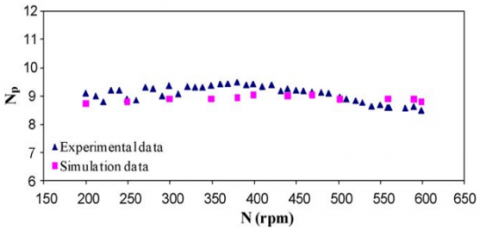
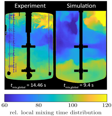
Zadghaffari et al. [10] Verified the flow field using the simulation model (LES) and the power consumed and mixing time numerically inside a stirred tank with baffled that is moved by 6-blade Rushton turbine. They studied the mixing time depending on the effect of the rotational speed of the blades, where different rotational speeds were used between (100-600 r.p.m) and compared the numerical results to calculate the mixing time with experimental correlations for previous studies, as shown in the Figure 3. Cheng et al. [12] Showed the amount of mixing time experimentally using water with three liquids of different densities inside an agitation tank. They also used four types of impellers (Rushton disk turbine, half circle blade disk turbine, 45° pitched blade turbine down flow, 45° pitched blade turbine flow) with different rotational speed between (461-329 r.p.m). They concluded that the mixing time decreases as the rotational speed increases, but the mixing time for the blades of (pitched blade turbine flow) type is low and for the blades of type (half circle blade disk turbine) is high as in the Figure 4. They also found that the amount of shear resulting from type (Rushton disk turbine) impeller is of high value, which gives less mixing time compared to other types of impellers. Ascanio et al. [26] Explained experimentally and numerically the method of calculating the actual mixing time by determining the degree of local mixing of low-density liquids inside a stirred tank. They found a good agreement in calculating the mixing time between experimental and numerical studies, as explained in the Figure 5. There are many numerical and experimental studies, as shown in Figure 6, which show the degree of convergence between the numerical and experimental studies in calculating the mixing time.
Figure 4. Mixing time value with speed of impeller for simulation and experimental correlations
Table 2. Power consumed correlation
|
Correlation |
Vessel Diameter (mm) |
R.P.M range |
Np Range |
Impeller Type |
Fluid |
Reference |
|
$\begin{gathered}\mathrm{N}_{\mathrm{p}} \mathrm{N}_{\mathrm{Re}}=90 \mathrm{~S}^{0.327} \\ \left(\frac{b}{\mathrm{D}}\right)^{0.635 \mathrm{~s}^{-0.280}}\end{gathered}$ |
100 |
50-1000 |
130.2 |
paddle impeller |
Laminar-Newtonian fluid |
[26] |
|
$\begin{gathered}\mathrm{N}_{\mathrm{P}}=9.74 \mathrm{~S}^{0.495} \\ (\mathrm{~b} / \mathrm{D})^{1.33 s^{0.108}}\end{gathered}$ |
100 |
50-5000 |
10.8 |
paddle impeller |
Turbulent-Newtonian fluid |
[26] |
|
$\begin{gathered}N_p=\frac{A}{N_{R e}} \\ A=14+\left(\frac{b}{D}\right)\left\{670\left(\frac{d}{D}-0.6\right)^{0.2}\right.+185\}\end{gathered}$ |
100 |
50-5000 |
122.7 |
paddle impeller |
Laminar-Newtonian fluid |
[27] |
|
$\begin{gathered}N_P=0.653 T^{0.26} \\ \left(\frac{T}{D}\right)^{0.11} \\ \left(\frac{C_1}{T}\right)^{-0.23} \\ n_h^{0.86} A^{1.82}\end{gathered}$ |
289 |
300-2000 |
1-5 |
pitched-blade |
Turbulent-Newtonian fluid |
[10] |
Figure 5. Different impeller speed against mixing time [12]
Figure 6. Comparison between the value of mixing time experimentally and numerically [27]
There are a few experimental techniques which is used to calculate the mixing time in the agitation tank.
2.2.1 Colorimetry
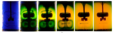
Colorimetry is one of the most common experimental methods for measuring mixing time, and this method is non-intrusive. Colorimetry is used not only to calculate the time needed to obtain good homogeneity but also to determine specific flow patterns within stirred tanks, as well as to detect the secondary flows resulting from the continuous stirring [4-45]. The method can be applied experimentally easily by injecting the tracer liquid and observing its spread with the liquid in the tank, Figure 7 shows this method [26].
Figure 7. Using colorimetry to measure mixing time [26]
2.2.2 The tomography with electrical resistances
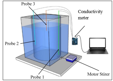
This method is a non-intrusive method Lagrangian technique for measuring the mixing time, as it depends on the electrical conductivity distribution of the gas-liquid flow in agitation tanks [26]. The application of this method is simple, as its application includes the difference in the conductivity used for the continuous phase from the conductivity of the other phases used [27], By observing some of the previous literature, there are other techniques to measure the mixing time such as Planar laser induced fluorescence and Conductometry and Ph as illustrated in Figure 8 experimentally inside the agitation tanks.
2.3 Impeller geometry
The fluid dynamics inside the stirred tanks are affected clearly depending on the shape of the impellers used and this effect can influence the mixing efficiency, mass and heat transfer [28], flow patterns, impeller power and shear rate [29], gas-liquid mixing, and vortex formation process. Over the past years, many researchers and engineers have been interested in designing mixers in the form and design of impellers suitable for the application, depending on the mixing process, whether it is liquid liquid, gas liquid, or solid liquid. In Figure 9, observe the correlation between the power number (Np) and the Reynolds number (Re) across seven different impeller designs. It's crucial to note that when Re is below 100, the flow transitions into a laminar state, resulting in significantly diminished mixing quality when employing these impellers [1].
Figure 8. Different type of experimental measuring devices for mixing time [30-32]
The type of impeller used in mixers depends on the specified application, the material properties to be mixed, and the required flow pattern. Here are some of the impellers commonly used in stirred tanks.
Figure 9. Power number versus impeller Reynolds number for seven different impellers [1]
2.3.1 Rushton disk turbine
The shape of these impellers is a disc with flat blades attached to it and finds widespread use in general mixing applications. This Impeller type is considered a radial flow impeller, that is commonly used for low viscosity and medium for liquids, as well as for single- and multi-phase mixing. This type of impeller provides turbulence, higher shear levels, and less pumping. The radial flow of these impellers is more uniform, but they expend more energy. Rushton impeller contain six blades and their standard dimensions (length $\frac{D}{4}$, width $\frac{D}{5}$, disk diameter $\frac{D}{4}$, width $\frac{D}{5}$, disk diameter $\left(\frac{33}{50} D-\frac{3}{4} D\right)$) [33], as shown in the Figure 10.
Figure 10. Ruston disk turbine
2.3.2 Pitched blade turbine
These impellers feature blades inclined at a certain angle to the shaft to produce significant radial flow. They are suitable for medium and high viscosity liquids. Ge et al. [34] Explained experimentally and numerically the Impact of a modified inclined blade turbine on the hydrodynamics inside a stirred vessel with the radial flow. It was verified experimentally by the solution method (particle image velocimetry) and numerical, the simulation model (k-ε) used to simulate the turbulent. They investigated several variables in their study, including turbulent kinetic energy and average speed, by the simulation model (k-ε) versus the experimental solution method (particle image velocimetry). The goal of their study is to obtain a good design of the impeller by changing only the shape of the blade to obtain a good mixing efficiency, Figure 11 show different types of pitched blade impeller design. The researchers concluded that some minor changes in the shape of the blade contributed to an enhancement in the number of average speeds near the impeller as well as an increase in the pumping efficiency for the improved impeller over the normal one.
Figure 11. different type of modified pitched blade impeller designs [34]
2.3.3 Anchor impeller
This type of impeller is distinctive and serves the purpose of achieving thorough mixing and preventing sedimentation. It includes blades designed to scrape remaining liquids on the walls and bottom of stirred tank mixers [1], Figure 12 shows the shape of anchor impeller.
Figure 12. Anchor impeller [35]
Figure 13. Helical impeller [1]
2.3.4 Helical ribbon impeller
This type of impeller is utilized for axial flows and high viscosity fluids. When using high-viscosity liquids, there is a need to use another type of impeller with close clearance, which is of the type (Helical impeller), as shown in the Figure 13. The clearance value used with this type of impeller is nearly (85-95%) the diameter of the tank. Low speed and high torque are mechanical features used for high-viscosity mixers that rotate large-sized impellers [35].
2.3.5 Butterfly impeller
Resembling butterfly wings, these impellers provide effective radial flow and are suitable for relatively high viscosity fluid applications and gentle mixing, as shown in Figure 14. Ramsay et al. [36] investigated experimentally the impact of butterfly-shaped impellers on the performance of a mixing process under laminar flow conditions using Newtonian fluids and viscoelastic materials (Boger) in an un-baffled stirred tank. Their objective is to determine mixing efficiency, power consumption, and mixing time values using the particle imaging method. The study aimed to assess the influence of utilizing a butterfly impeller at rotational speeds between 40-60 r.p.m. Their results showed the (Np) for the butterfly impeller was 0.6, which is significantly lower than that of other impeller types such as the Rushton turbine and pitched blade, with power number values of 4.9 and 0.8. This appears in the use of the butterfly impeller leads to a notable reduction in power consumption compared to other impeller designs, while simultaneously enhancing mixing efficiency. However, noted that the mixing time is prolonged due to elastic effects.
Figure 14. butterfly impeller shape [36]
Figure 15. Cowles impeller [37]
2.3.6 Cowles impeller
Cowles impellers are equipped with serrated blades and are designed for high shear applications as shown in Figure 15. These blades are beneficial for breaking up agglomerations and promoting dispersion. Antognoli et al. [37] numerically studied the process of mixing high-viscosity paints inside a stirred tank using Cowles Impellers. They utilized various dyes in conjunction with the main liquid and stirred them inside the tank using blades to achieve a uniform one-color paint. This paint is commonly employed for coloring leather in the tanning industry, and the mixing process involves high rotational speeds ranging from 3000 to 5000 RPM.
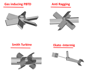
It is possible to classify impellers according to the flow patterns generated in rotary mixers, including: radial flow, axial flow, tangential flow, and high shear flow. The Table 3 attached below shows the impellers types of depending on the application used and the flow pattern.
Table 3. Impeller type in stirred tank
|
Impeller |
Application |
Flow Pattern |
Shape |
|
Open impellers |
Efficient heat transfer, solid suspensions |
axial |
|
|
Open impellers |
Liquid mixing, heat transfer, gas dispersion |
radial |
|
|
Close impellers (high viscosity) |
High viscosity mixing |
Tangential flow, Axial flow |
|
|
Gas dispersion impeller |
Fermenters devices |
radial |
Ayranci et al. [38] surveyed the effect of changing the impeller geometry and using different diameters, along with varying clearances, on the process of suspending solids in a stirred tank, both experimentally and theoretically. In their study, the researchers selected Two Lightnin A310 impellers with different diameters (tank diameter/2 and tank diameter/3), as well as a variable clearance. They conducted their experimental study using the particle image velocimetry method to determine the average velocities and turbulent fluctuating speeds. Additionally, in the theoretical study, they utilized the solution method of LES (large eddy simulations). The results of the researchers revealed differences in the suspension of solids based on the impeller diameters. Specifically, they found that the impeller diameter (tank diameter/3) is more efficient than (tank diameter/2) in the process of solid particles suspending in a liquid because it causes less energy loss due to turbulent energy dispersion.
Ameur [41] explained numerically the effect of the impeller shape on the energy efficiency of the flow process of complex fluids inside a stirred tank, the researcher used four types of vanes (Max-blend, anchor, gate, and double helical ribbon impeller), as shown in Figure 9. Through his study, he demonstrated the best types of impeller used in terms of the actual performance of the mixing process. He concluded from his study that the use of the impeller (double helical ribbon) is effective in the mixing process, but it requires more energy consumption. Additionally, it was concluded that the use of the blade type (Max-blend) is effective in the process of mixing the complex liquids with less energy consumption.
Martínez-Delgadillo et al. [39] explained experimentally and numerically the effect of changing the design of the blades of the turbine using different shapes (U and V grooved) on the process of turbulent flow and energy consumption inside a baffled stirred tank. In their study, the researchers used two types of blades (U and V grooved) and an angle (45o) and compared it with the regular blade and showed its effect on the energy consumption process, average speeds, and production the kinetic energy and trailing vortices were solved theoretically by using the solution model (detached eddy simulation (DES) as well as the use of the solution method Particle image velocimetry to ensure the validity of the results experimental. The researchers concluded that the use of shapes (U andV) for the blades contributes to reducing the dissipated energy by (6% and 4%and) respectively when using the range of Reynolds numbers (40 E3 < Re < 125 E3) Compared to the regular blade.
Gu el at. [40] Studied the effect of the mixing of a solid-liquid in a stirred vessel using three types of impeller (pitched-blade, Fractal impeller, jagged shape impeller) theoretically. In their theoretical study, they used model ($k-\varepsilon$) for turbulent flow, model (Eulerian-Eulerian) to simulate the multiphase flow and model (multiple reference frames (MRF)) to simulate the impeller rotation. Studying the effect of variables (impeller rotation speed, type of impeller, blade shape of the impeller). The results of the researchers showed the degree of mixing between liquid and solid increases with the rise in the impeller speed of rotational. They also proved the shape of the impeller with a fractal shape is more efficient than the impeller with a jagged shape in the mixing process. In addition, they found that the fractal-shaped impeller caused a lower impeller back vortex volume and lower energy consumption compared to other types with the same rotation speed.
Ameur [41] Investigated numerically the influence of changing the impeller shape on the quality of the Mixing effectiveness in an agitated vessel containing a two-phase flow (gas-liquid). It used (CFD) to verify the effect of four different designs of blade angles (15o,30o,45o,60o) on the quality of the mixing efficiency. Method (Eulerian-Eulerian) was used to model the behavior of the multiphase flow and the method ($k-\varepsilon$) to model the turbulence. Moreover, the method (CFD) was used to study the influence of the shape of the impeller on power consumption as well. The researcher concluded that the impeller with angle (30o) has the best mixing quality compared to the other angles, and it was also noted that the largest vortex in the tank at the angle (30o), showed its clear effect on the quality of mixing.
Hoseini et al. [42] Studied numerically different designs of impellers (U- and V-shape) on the mixing performance inside a stirred tank. In their study, the energy consumption inside an agitation tank was examined using (Rushton turbine) experimentally to confirm the numerical results. They studied the relationship between fluid and steel using the analysis (Fluid-Structure Interaction (FSI)). They concluded from their study that the use of the different designs of the impellers (U- and V-shape) improve the power consumption and the flow pattern for the stirred tank, where they found in the case of the impellers ((U- and V-shape) that the power consumption ratio decreases by an amount (21% and 48%) respectively.
Gu et al. [43] Demonstrated experimentally the effect of the liquid gas mixing process inside a stirred tank using fractal-shaped blades and compared them with pitched blades. The aim of their research, through the use of fractal-shaped blades, is how to obtain the best adaptation for the liquid-gas mixing process. They measured the multiscale entropy value (MSE) to describe the mixing properties of the two phases and measured the relative energy demand to describe the amount of energy consumption, and the size of a bubble was calculated to describe the dispersion of gas efficiency. They showed that the use of the fractal impeller type can upgrade the process of (MSE) by (21.69%) and improve the amount of energy demand by (11.94%) more than using the pitched blades, the study also proved that the use of fractal impellers lowered the size of the bubbles as well as increased the mass transfer process by (11.07%).
In Table 4 shown in appendix, we present a summary of previous studies on rotary mixers, reviewing the mathematical model, the solution methods used, the type of flow, as well as the shape of the impellers used.
The solution using computational fluid dynamic (CFD) of the mixing process inside agitation tanks requires consideration of several aspects. First, describe the domain to be studied. Secondly, simulate the movement of the impeller inside the tank and consider the condition of the tank whether it contains baffles or not. Among these equations that describe the movement of a fluid are the equations of transport and conservation. For example, if a small volume of liquid is in motion, it will be under two important influences: (1) the volume will move from its normal place or rotate, (2) It will deform due to expansion along one or more axes or due to angular expansion that changes its shape. The transition process is often called (convection) and the deformation process (diffusion). Below we will describe some equations that affect the movement and transport of fluid [44].
3.1 Continuity equation
The form of continuity equation is:
$\frac{\partial \rho}{\partial t}+\nabla \cdot(\rho U)=0$ (7)
3.2 Momentum equations
The equations of momentum in the three directions (x, y, z). Also called Naiver-Stoke equations is [45]:
x-direction:
$\begin{aligned} \frac{\partial(\rho u)}{\partial t}+\nabla \cdot(\rho u u)= & -\frac{\partial p}{\partial x}+\nabla \cdot \mu\left(\nabla \cdot u-\frac{2}{3}\left(\frac{\partial u}{\partial x}\right)\right)+\rho g_x +F_x\end{aligned}$ (8)
y-direction:
$\begin{aligned} \frac{\partial(\rho v)}{\partial t}+\nabla \cdot(\rho v u)= & -\frac{\partial p}{\partial y}+\nabla \cdot \mu\left(\nabla \cdot v-\frac{2}{3}\left(\frac{\partial v}{\partial y}\right)\right)+\rho g_y+F_y\end{aligned}$ (9)
z-direction:
$\begin{aligned} \frac{\partial(\rho w)}{\partial t}+\nabla \cdot(\rho w u) & =-\frac{\partial p}{\partial y}+\nabla \cdot \mu\left(\nabla \cdot w-\frac{2}{3}\left(\frac{\partial w}{\partial z}\right)\right) +\rho g_z+F_z\end{aligned}$ (10)
3.3 Turbulence
A number of dimensionless parameters are used in fluid dynamics to classify different flow patterns and classify fluids. One of these dimensionless numbers is the Reynolds number. Flow inside mixers, the impeller Reynolds number can be represented by the following relationship:
$R e=\frac{\rho N D^2}{\mu}$ (11)
The lower values of (Re) represent laminar flow, the higher value represents turbulent flow, and between them represents the transitional, which in the case of rotating mixers is between (50-5000) [35].
There are therefore several models that describe turbulent flow, including:
The Reynolds averaged naiver stokes (RANS) equation is [35]:
$\begin{gathered}\frac{\partial(\rho u)}{\partial t}+\nabla \cdot(\rho u u)=-\nabla(\mathrm{p})+\nabla \cdot \mu\left(\nabla \cdot u-\frac{2}{3}(\nabla \cdot \mathrm{u})\right)+ \rho g+F_i+\nabla \cdot\left(-\rho u^{\prime} u^{\prime}\right)\end{gathered}$ (12)
$u^{\prime} u^{\prime}$ called the Reynolds stresses.
$k-\varepsilon$: This model is a two equation and is one of the most powerful computational models used to calculate complex turbulent flows, and it is mathematically stable. The two equations are turbulence kinetic energy equation (k) and the turbulence dissipation rate equation ($\varepsilon$) [46]:
$\frac{\partial(\rho k)}{\partial t}+\operatorname{div}(\rho u k)=\operatorname{div}\left(\left(\mu+\frac{\mu_t}{\sigma_k}\right) \operatorname{div}(k)\right)+G_K-\rho \varepsilon$ (13)
$\begin{aligned} \frac{\partial(\rho \varepsilon)}{\partial t}+\operatorname{div}(\rho u \varepsilon) & =\operatorname{div}\left(\left(\mu+\frac{\mu_t}{\sigma_{\varepsilon}}\right) \operatorname{div}(\varepsilon)\right)+C_1 \frac{\varepsilon}{k} G_K \\ & -C_2 \frac{\varepsilon^2}{k} \rho\end{aligned}$ (14)
The quantities C1, C2 are empirical constants $\mu_{\mathrm{t}}$is turbulence viscosity (kg/m.s), $\sigma_{\varepsilon}$ is the turbulent Prandtl number for $\varepsilon, \sigma_k$ is turbulent Prandtl number for k. $G_K$ generation term for turbulence and can be represented by an equation:
$G_K=\mu_t\left(\nabla u+(\nabla u)^T \nabla u\right.$ (15)
$\mu_t=\rho C_\mu \frac{k^2}{\varepsilon}$ (16)
where, $C_\mu=0.09$ constant from experimental data.
1- Through analysis of previous literature related to the power consumption process of stirred tank mixers, a complex interaction between factors was revealed, including impeller geometry, operating conditions, and fluid properties. Understanding and improving power consumption is crucial to achieving efficient mixing processes in industrial applications. It is important for future studies to focus on developing advanced computational models as well as using techniques in experimental studies to understand the complex dynamics of stirred mixers and work on designing more efficient systems in terms of energy consumption. Ultimately this contributes to a sustainable and cost-effective manufacturing process.
2- From previous studies related to studying the mixing time in stirred tank mixers, we conclude that the fluids characteristics used and the impeller shape, affect the mixing time. Obtaining ideal mixing times is pivotal and important in many applications, especially the pharmaceutical industry and food industries, and other applications. Despite ongoing work to understand the complex dynamics, there is an urgent need to enhance mixing efficiency, reduce processing times, and improve product quality. Faster mixing times mean faster batch turnover, resulting in increased productivity. This is especially important in industries where production throughput is a critical factor. Improved mixing efficiency ensures better homogeneity and consistency of the final product. Overall, reducing mixing times and improving mixing efficiency in stirred tank mixers results in cost savings, improved product quality, and increased manufacturers' competitiveness in various industries. The future research should be focus on bridging the gap between theoretical and experimental study through the use of powerful solution models and modern techniques in experimental study, which ultimately pave the way for improvement in mixing times in diverse industrial environments.
3- It is clear that impeller geometry is considered an important factor affecting the effectiveness of mixers for stirred tanks, as previous studies have shown the extent to which the energy consumption process and mixing times are greatly influenced by the impeller shape and Mixing effectiveness. Choosing the shape of the impeller is an important factor in many industries that use stirred tanks, the most important of which is the chemical industry. It is also necessary to comprehend the relationship between fluid dynamics and impeller geometry to obtain efficient and cost-effective solutions. Improving the geometry of the impeller can improve energy efficiency by reducing energy consumption while maintaining efficient mixing. The shape of the impeller blades affects the fluid flow patterns within the tank. By changing the shape of the impeller, it is possible to manipulate the fluid flow to better suit the mixing requirements of the process. This can help prevent dead areas. It is recommended that future studies delve into studying the dynamics of mixers and produce impellers specifically designed for specific applications. Taking these designs into consideration, it is not possible to only consider changing the traditional parameters, as 3D printers can be used in the design. By using diversity in the design of impeller geometry, new levels can be opened in terms of efficiency, diversity, and accuracy in mixing operations, leading to progress in industrial processes.
|
$N_P$ |
Dimensionless power number |
|
P |
Power (W) |
|
ρ |
Fluid density (Kg/m3) |
|
N |
Impeller speed (Revolution per minute) |
|
U |
General velocity term [m/s] |
|
u |
x-velocity (m/s) |
|
v |
y-velocity (m/s) |
|
w |
z-velocity (m/s) |
|
C1, C2 |
Empirical constants |
|
$G_K$ |
Generation term |
|
D |
Impeller diameter (m) |
|
k |
Kinetic energy |
|
$\mu_t$ |
Turbulence viscosity (kg/m.s) |
|
σε |
The turbulent Prandtl number for ε |
|
σk |
Turbulent Prandtl number for k |
|
τ |
The torque of the impeller shaft (N.m) |
|
F |
Force (N) |
|
$d_l$ |
Arm length (m) |
|
$N_{Re}$ |
The impeller Reynolds number |
|
S |
Number of blades |
|
b |
The blade width (m) |
|
Re |
Reynolds number |
|
tm |
Mixing time (s) |
|
Abbreviations |
|
|
RPM |
Revolution per minute |
|
LES |
Large-eddy simulation |
|
DES |
Detached eddy simulation |
|
MRF |
Multiple reference frames |
|
CFD |
Commotional fluid dynamics |
|
FSI |
Fluid-structure interaction |
|
MSE |
Multi-scale entropy |
|
RANS |
Reynolds-averaged naiver-stokes |
|
Greek symbols |
|
|
∇ |
Laplace operator |
|
Δ |
Difference |
|
ε |
Dissipation rate |
|
μ |
Dynamic viscosity [m2/s] |
|
ρ |
Density [kg/m3] |
[1] Paul, E.L., Atiemo-Obeng, V.A., Kresta, S.M. (2004). Handbook of Industrial Mixing. New York: Wiley-Blackwell. https://doi.org/10.1002/0471451452
[2] Ascanio, G., Castro, B., Galindo, E. (2004). Measurement of power consumption in stirred vessels-a review. Chemical Engineering Research and Design, 82(9): 1282-1290. https://doi.org/10.1205/cerd.82.9.1282.44164
[3] Armenante, P.M., Uehara Nagamine, E. (1997). Solid suspension and power dissipation in stirred tanks agitated by one or two impellers at low off-bottom impeller clearances. In Proceedings of the 9th European Conference on Mixing. Nancy, France. https://digitalcommons.njit.edu/theses/1071.
[4] Dohi, N., Takahashi, T., Minekawa, K., Kawase, Y. (2004). Power consumption and solid suspension performance of large-scale impellers in gas–liquid–solid three-phase stirred tank reactors. Chemical Engineering Journal, 97(2-3): 103-114. https://doi.org/10.1016/S1385-8947(03)00148-7
[5] Armenante, P.M., Chang, G.M. (1998). Power consumption in agitated vessels provided with multiple-disk turbines. Industrial & Engineering Chemistry Research, 37(1): 284-291. https://doi.org/10.1021/ie970583u
[6] Armenante, P.M., Mazzarotta, B., Chang, G.M. (1999). Power consumption in stirred tanks provided with multiple pitched-blade turbines. Industrial & Engineering Chemistry Research, 38(7): 2809-2816. https://doi.org/10.1021/ie980692o
[7] Paper, C., Kada, B., Mebarki, B., Al-farhany, K. (2023). Numerical investigation of laminar stirring viscous fluid inside stirred tank with newly Rushton turbine design. AIP Conference Proceedings, 2787: 090038. https://doi.org/10.1063/5.0148171
[8] Gu, D., Xu, H., Ye, M., Wen, L. (2022). Design of impeller blades for intensification on fluid mixing process in a stirred tank. Journal of the Taiwan Institute of Chemical Engineers, 138: 104475. https://doi.org/10.1016/j.jtice.2022.104475
[9] Amiraftabi, M., Khiadani, M., Mohammed, H.A. (2020). Performance of a dual helical ribbon impeller in a two-phase (gas-liquid) stirred tank reactor. Chemical Engineering and Processing - Process Intensification, vol. 148:107811. https://doi.org/10.1016/j.cep.2020.107811
[10] Zadghaffari, R., Moghaddas, J.S., Revstedt, J. (2010). Large-eddy simulation of turbulent flow in a stirred tank driven by a Rushton turbine. Computers & Fluids, 39(7): 1183-1190. https://doi.org/10.1016/j.compfluid.2010.03.001
[11] Taghavi, M., Zadghaffari, R., Moghaddas, J., Moghaddas, Y. (2011). Experimental and CFD investigation of power consumption in a dual Rushton turbine stirred tank. Chemical Engineering Research and Design, 89(3): 280-290. https://doi.org/10.1016/j.cherd.2010.07.006
[12] Cheng, D., Cheng, J., Li, X., Wang, X., Yang, C., Mao, Z.S. (2012). Experimental study on gas-liquid-liquid macro-mixing in a stirred tank. Chemical Engineering Science, 75: 256-266. https://doi.org/110.1016/j.ces.2012.03.035
[13] Zadghaffari, R., Moghaddas, J., Revstedt, J. (2009). Study of flow field, power and mixing time in a two-phase stirred vessel with dual Rushton impellers: Experimental observation and CFD simulation. Chemical Product and Process Modeling, 4(1). https://doi.org/10.2202/1934-2659.1284
[14] Murthy, S., Jayanti, S. (2002). CFD study of power and mixing time for paddle mixing in unbaffled vessels. Chemical Engineering Research and Design, 80(5): 482-498. https://doi.org/10.1205/026387602320224067
[15] Pandit, A.B., Joshi, J.B. (1983). Mixing in mechanically agitated gas-liquid contactors, bubble columns and modified bubble columns. Chemical Engineering Science, 38(8): 1189-1215. https://doi.org/10.1016/0009-2509(83)80040-2
[16] Oldshue, J.Y. (1976). Mixing—principles and applications, by Shinji Nagata, Published by Halsted Press, 458 pages, $32.50. AIChE, 22(2): 412-413. https://doi.org/10.1002/aic.690220234
[17] Dutta, N.N., Pangarkar, V.G. (1995). Critical impeller speed for solid suspension in multi‐impeller three phase agitated contactors. The Canadian Journal of Chemical Engineering, 73: 273-283. https://doi.org/10.1002/cjce.5450730302
[18] Kaiser, S.C., Werner, S., Jossen, V., Blaschczok, K., Eibl, D. (2018). Power input measurements in stirred bioreactors at laboratory scale. JoVE Journal, 2018(135): e56078. https://doi.org/10.3791/56078
[19] Steiros, K., Bruce, P.J.K., Buxton, O.R.H., Vassilicos, J.C. (2017). Power consumption and form drag of regular and fractal‐shaped turbines in a stirred tank. AIChE Journal, 63(2): 843-854. https://doi.org/10.1002/aic.15414
[20] Afshar Ghotli, R., Raman, A.A.A., Ibrahim, S., Baroutian, S. (2013). Liquid-liquid mixing in stirred vessels: A review. Chemical Engineering Communications, 200(5): 595-627. https://doi.org/10.1080/00986445.2012.717313
[21] Heidari, A. (2020). CFD simulation of impeller shape effect on quality of mixing in two-phase gas–liquid agitated vessel. Chinese Journal of Chemical Engineering, 28(11): 2733-2745. https://doi.org/10.1016/j.cjche.2020.06.036
[22] Wichterle, K. (1994). Heat transfer in agitated vessels. Chemical Engineering Science, 49(9): 1480-1483. https://doi.org/10.1016/0009-2509(94)85075-5
[23] Sánchez, A., Martinez, A., Torres, L., Galindo, E. (1992). Power consumption of three impeller combinations in mixing xanthan fermentation broths. Process Biochemistry, 27(6): 351-365. https://doi.org/10.1016/0032-9592(92)87014-8
[24] Regestein, L., Giese, H., Zavrel, M., Büchs, J. (2013). Comparison of two methods for designing calorimeters using stirred tank reactors. Biotechnology and Bioengineering, 110(1): 180-190. https://doi.org/10.1002/bit.24601
[25] Oosterhuis, N.M.G., Kossen, N.W.F. (1981). Power input measurements in a production scale bioreactor. Biotechnology Letters, 3: 645-650. https://doi.org/10.1007/BF00158694
[26] Ascanio, G. (2015). Mixing time in stirred vessels: A review of experimental techniques. Chinese Journal of Chemical Engineering, 23(7): 1065-1076. https://doi.org/10.1016/j.cjche.2014.10.022
[27] Fitschen, J., Hofmann, S., Wutz, J., Kameke, A.V., Hoffmann, M., Wucherpfennig, T., Schlüter, M. (2021). Novel evaluation method to determine the local mixing time distribution in stirred tank reactors. Chemical Engineering Science: X, 10: 100098. https://doi.org/10.1016/j.cesx.2021.100098
[28] Holden, P.J., Wang, M., Mann, R., Dickin, F.J., Edwards, R.B. (1998). Imaging stirred‐vessel macromixing using electrical resistance tomography. AIChE Journal, 44(4): 780-790. https://doi.org/10.1002/aic.690440403
[29] Mann, R., Dickin, F.J., Wang, M., Dyakowski, T., Williams, R.A., Edwards, R.B., Forrest, A.E., Holden, P.J. (1997). Application of electrical resistance tomography to interrogate mixing processes at plant scale. Chemical Engineering Science, 52(13): 2087-2097. https://doi.org/10.1016/S0009-2509(97)00036-5
[30] Hu, Y., Wang, W., Shao, T., Yang, J., Cheng, Y. (2012). Visualization of reactive and non-reactive mixing processes in a stirred tank using planar laser induced fluorescence (PLIF) technique. Chemical Engineering Research and Design, 90(4): 524-533. https://doi.org/10.1016/j.cherd.2011.08.021
[31] Hashemi, N., Ein-Mozaffari, F., Upreti, S.R., Hwang, D.K. (2016). Experimental investigation of the bubble behavior in an aerated coaxial mixing vessel through electrical resistance tomography (ERT). Chemical Engineering Journal, 289: 402-412. https://doi.org/10.1016/j.cej.2015.12.077
[32] Madhania, S., Fathonah, N.N., Kusdianto, Nurtono, T., Winardi, S. (2021). Turbulence modeling in side-entry stirred tank mixing time determination. MATEC Web Conferences, 333: 02003. https://doi.org/10.1051/matecconf/202133302003
[33] Dickey, D.S. (2001). Mixing Equipment (Impeller Type): AIChE Equipment Testing Procedure. New York: AIChE.
[34] Ge, C.Y., Wang, J.J., Gu, X.P., Feng, L.F. (2014). CFD simulation and PIV measurement of the flow field generated by modified pitched blade turbine impellers. Chemical Engineering Research and Design, 92(6): 1027-1036. https://doi.org/10.1016/j.cherd.2013.08.024
[35] Ramsay, J., Simmons, M.J.H., Ingram, A., Stitt, E.H. (2016). Mixing of Newtonian and viscoelastic fluids using ‘butterfly’ impellers. Chemical Engineering Science, 139: 125-141. https://doi.org/10.1016/j.ces.2015.09.026
[36] Ramsay, J., Simmons, M.J.H., Ingram, A., Stitt, E.H. (2016). Mixing of Newtonian and viscoelastic fluids using ‘butterfly’ impellers. Chemical Engineering Science, 139: 125-141. https://doi.org/10.1016/j.ces.2015.09.026
[37] Antognoli, M., Galletti, C., Bacci di Capaci, R., Pannocchia, G., Scali, C. (2019). Numerical investigation of the mixing of highly viscous liquids with Cowles impellers. Chemical Engineering Transactions, 74: 973-978. https://doi.org/10.3303/CET1974163
[38] Ayranci, I., Machado, M.B., Madej, A.M., Derksen, J.J., Nobes, D.S., Kresta, S.M. (2012). Effect of geometry on the mechanisms for off-bottom solids suspension in a stirred tank. Chemical Engineering Science, 79: 163-176. https://doi.org/10.1016/j.ces.2012.05.028
[39] Martínez-Delgadillo, S.A., Alonzo-Garcia, A., Mendoza-Escamilla, V.X., González-Neria, I., Antonio Yáñez-Varela, J. (2019). Analysis of the turbulent flow and trailing vortices induced by new design grooved blade impellers in a baffled tank. Chemical Engineering Journal, 358: 225-235. https://doi.org/10.1016/j.cej.2018.10.015
[40] Gu, D., Cheng, C., Liu, Z., Wang, Y. (2019). Numerical simulation of solid-liquid mixing characteristics in a stirred tank with fractal impellers. Advanced Powder Technology, 30(10): 2126-2138. https://doi.org/10.1016/j.apt.2019.06.028
[41] Ameur, H. (2015). Energy efficiency of different impellers in stirred tank reactors. Energy, 93: 1980-1988. https://doi.org/10.1016/j.energy.2015.10.084
[42] Hoseini, S.S., Najafi, G., Ghobadian, B., Akbarzadeh, A.H. (2021). Impeller shape-optimization of stirred-tank reactor: CFD and fluid structure interaction analyses. Chemical Engineering Journal, 413: 127497. https://doi.org/10.1016/j.cej.2020.127497
[43] Gu, D., Mei, Y., Wen, L., Wang, X., Liu, Z. (2021). Chaotic mixing and mass transfer characteristics of fractal impellers in gas-liquid stirred tank. Journal of the Taiwan Institute of Chemical Engineers, 121: 20-28. https://doi.org/10.1016/j.jtice.2021.03.038
[44] Guo, C., Xue, S., Li, W., Qin, H., Guo, J., Zhang, J. (2018). Investigation of power characteristics in a novel cup-shaped-blade mixer. Chemical Engineering and Processing - Process Intensification, 125: 150-162. https://doi.org/10.1016/j.cep.2018.01.025
[45] Xiong, X., Liu, Z., Tao, C., Wang, Y., Fei, W. (2022). Study on instability strengthening of flow field in stirred tank. Journal of the Taiwan Institute of Chemical Engineers, 134: 104284. https://doi.org/10.1016/j.jtice.2022.104284
[46] John, T.P., Fonte, C.P., Kowalski, A., Rodgers, T.L. (2023). The effect of axial impeller geometry on the link between power and flow numbers. AIChE Journal, 69(3): 1-15. https://doi.org/10.1002/aic.17871